EP0895083B1 - Reaktionsstellenarray, Verfahren zu seiner Herstellung, Reaktionsverfahren unter seiner Verwendung und quantitatives Bestimmungsverfahren für eine Substanz in einer Probelösung unter seiner Verwendung - Google Patents
Reaktionsstellenarray, Verfahren zu seiner Herstellung, Reaktionsverfahren unter seiner Verwendung und quantitatives Bestimmungsverfahren für eine Substanz in einer Probelösung unter seiner Verwendung Download PDFInfo
- Publication number
- EP0895083B1 EP0895083B1 EP98306110A EP98306110A EP0895083B1 EP 0895083 B1 EP0895083 B1 EP 0895083B1 EP 98306110 A EP98306110 A EP 98306110A EP 98306110 A EP98306110 A EP 98306110A EP 0895083 B1 EP0895083 B1 EP 0895083B1
- Authority
- EP
- European Patent Office
- Prior art keywords
- region
- process according
- reaction
- reaction site
- support
- Prior art date
- Legal status (The legal status is an assumption and is not a legal conclusion. Google has not performed a legal analysis and makes no representation as to the accuracy of the status listed.)
- Expired - Lifetime
Links
Images

Classifications
-
- G—PHYSICS
- G01—MEASURING; TESTING
- G01N—INVESTIGATING OR ANALYSING MATERIALS BY DETERMINING THEIR CHEMICAL OR PHYSICAL PROPERTIES
- G01N33/00—Investigating or analysing materials by specific methods not covered by groups G01N1/00 - G01N31/00
- G01N33/48—Biological material, e.g. blood, urine; Haemocytometers
- G01N33/50—Chemical analysis of biological material, e.g. blood, urine; Testing involving biospecific ligand binding methods; Immunological testing
- G01N33/53—Immunoassay; Biospecific binding assay; Materials therefor
- G01N33/543—Immunoassay; Biospecific binding assay; Materials therefor with an insoluble carrier for immobilising immunochemicals
- G01N33/544—Immunoassay; Biospecific binding assay; Materials therefor with an insoluble carrier for immobilising immunochemicals the carrier being organic
- G01N33/545—Synthetic resin
-
- B—PERFORMING OPERATIONS; TRANSPORTING
- B01—PHYSICAL OR CHEMICAL PROCESSES OR APPARATUS IN GENERAL
- B01J—CHEMICAL OR PHYSICAL PROCESSES, e.g. CATALYSIS OR COLLOID CHEMISTRY; THEIR RELEVANT APPARATUS
- B01J19/00—Chemical, physical or physico-chemical processes in general; Their relevant apparatus
- B01J19/0046—Sequential or parallel reactions, e.g. for the synthesis of polypeptides or polynucleotides; Apparatus and devices for combinatorial chemistry or for making molecular arrays
-
- G—PHYSICS
- G01—MEASURING; TESTING
- G01N—INVESTIGATING OR ANALYSING MATERIALS BY DETERMINING THEIR CHEMICAL OR PHYSICAL PROPERTIES
- G01N33/00—Investigating or analysing materials by specific methods not covered by groups G01N1/00 - G01N31/00
- G01N33/48—Biological material, e.g. blood, urine; Haemocytometers
- G01N33/50—Chemical analysis of biological material, e.g. blood, urine; Testing involving biospecific ligand binding methods; Immunological testing
- G01N33/53—Immunoassay; Biospecific binding assay; Materials therefor
- G01N33/543—Immunoassay; Biospecific binding assay; Materials therefor with an insoluble carrier for immobilising immunochemicals
- G01N33/54366—Apparatus specially adapted for solid-phase testing
-
- B—PERFORMING OPERATIONS; TRANSPORTING
- B01—PHYSICAL OR CHEMICAL PROCESSES OR APPARATUS IN GENERAL
- B01J—CHEMICAL OR PHYSICAL PROCESSES, e.g. CATALYSIS OR COLLOID CHEMISTRY; THEIR RELEVANT APPARATUS
- B01J2219/00—Chemical, physical or physico-chemical processes in general; Their relevant apparatus
- B01J2219/00274—Sequential or parallel reactions; Apparatus and devices for combinatorial chemistry or for making arrays; Chemical library technology
- B01J2219/00277—Apparatus
- B01J2219/00279—Features relating to reactor vessels
- B01J2219/00306—Reactor vessels in a multiple arrangement
- B01J2219/00313—Reactor vessels in a multiple arrangement the reactor vessels being formed by arrays of wells in blocks
- B01J2219/00315—Microtiter plates
- B01J2219/00317—Microwell devices, i.e. having large numbers of wells
-
- B—PERFORMING OPERATIONS; TRANSPORTING
- B01—PHYSICAL OR CHEMICAL PROCESSES OR APPARATUS IN GENERAL
- B01J—CHEMICAL OR PHYSICAL PROCESSES, e.g. CATALYSIS OR COLLOID CHEMISTRY; THEIR RELEVANT APPARATUS
- B01J2219/00—Chemical, physical or physico-chemical processes in general; Their relevant apparatus
- B01J2219/00274—Sequential or parallel reactions; Apparatus and devices for combinatorial chemistry or for making arrays; Chemical library technology
- B01J2219/00277—Apparatus
- B01J2219/00351—Means for dispensing and evacuation of reagents
- B01J2219/00378—Piezoelectric or ink jet dispensers
-
- B—PERFORMING OPERATIONS; TRANSPORTING
- B01—PHYSICAL OR CHEMICAL PROCESSES OR APPARATUS IN GENERAL
- B01J—CHEMICAL OR PHYSICAL PROCESSES, e.g. CATALYSIS OR COLLOID CHEMISTRY; THEIR RELEVANT APPARATUS
- B01J2219/00—Chemical, physical or physico-chemical processes in general; Their relevant apparatus
- B01J2219/00274—Sequential or parallel reactions; Apparatus and devices for combinatorial chemistry or for making arrays; Chemical library technology
- B01J2219/00277—Apparatus
- B01J2219/00497—Features relating to the solid phase supports
- B01J2219/00527—Sheets
-
- B—PERFORMING OPERATIONS; TRANSPORTING
- B01—PHYSICAL OR CHEMICAL PROCESSES OR APPARATUS IN GENERAL
- B01J—CHEMICAL OR PHYSICAL PROCESSES, e.g. CATALYSIS OR COLLOID CHEMISTRY; THEIR RELEVANT APPARATUS
- B01J2219/00—Chemical, physical or physico-chemical processes in general; Their relevant apparatus
- B01J2219/00274—Sequential or parallel reactions; Apparatus and devices for combinatorial chemistry or for making arrays; Chemical library technology
- B01J2219/00583—Features relative to the processes being carried out
- B01J2219/00603—Making arrays on substantially continuous surfaces
- B01J2219/00605—Making arrays on substantially continuous surfaces the compounds being directly bound or immobilised to solid supports
- B01J2219/0061—The surface being organic
-
- B—PERFORMING OPERATIONS; TRANSPORTING
- B01—PHYSICAL OR CHEMICAL PROCESSES OR APPARATUS IN GENERAL
- B01J—CHEMICAL OR PHYSICAL PROCESSES, e.g. CATALYSIS OR COLLOID CHEMISTRY; THEIR RELEVANT APPARATUS
- B01J2219/00—Chemical, physical or physico-chemical processes in general; Their relevant apparatus
- B01J2219/00274—Sequential or parallel reactions; Apparatus and devices for combinatorial chemistry or for making arrays; Chemical library technology
- B01J2219/00583—Features relative to the processes being carried out
- B01J2219/00603—Making arrays on substantially continuous surfaces
- B01J2219/00605—Making arrays on substantially continuous surfaces the compounds being directly bound or immobilised to solid supports
- B01J2219/00612—Making arrays on substantially continuous surfaces the compounds being directly bound or immobilised to solid supports the surface being inorganic
-
- B—PERFORMING OPERATIONS; TRANSPORTING
- B01—PHYSICAL OR CHEMICAL PROCESSES OR APPARATUS IN GENERAL
- B01J—CHEMICAL OR PHYSICAL PROCESSES, e.g. CATALYSIS OR COLLOID CHEMISTRY; THEIR RELEVANT APPARATUS
- B01J2219/00—Chemical, physical or physico-chemical processes in general; Their relevant apparatus
- B01J2219/00274—Sequential or parallel reactions; Apparatus and devices for combinatorial chemistry or for making arrays; Chemical library technology
- B01J2219/00583—Features relative to the processes being carried out
- B01J2219/00603—Making arrays on substantially continuous surfaces
- B01J2219/00605—Making arrays on substantially continuous surfaces the compounds being directly bound or immobilised to solid supports
- B01J2219/00614—Delimitation of the attachment areas
- B01J2219/00617—Delimitation of the attachment areas by chemical means
- B01J2219/00619—Delimitation of the attachment areas by chemical means using hydrophilic or hydrophobic regions
-
- B—PERFORMING OPERATIONS; TRANSPORTING
- B01—PHYSICAL OR CHEMICAL PROCESSES OR APPARATUS IN GENERAL
- B01J—CHEMICAL OR PHYSICAL PROCESSES, e.g. CATALYSIS OR COLLOID CHEMISTRY; THEIR RELEVANT APPARATUS
- B01J2219/00—Chemical, physical or physico-chemical processes in general; Their relevant apparatus
- B01J2219/00274—Sequential or parallel reactions; Apparatus and devices for combinatorial chemistry or for making arrays; Chemical library technology
- B01J2219/00583—Features relative to the processes being carried out
- B01J2219/00603—Making arrays on substantially continuous surfaces
- B01J2219/00605—Making arrays on substantially continuous surfaces the compounds being directly bound or immobilised to solid supports
- B01J2219/00614—Delimitation of the attachment areas
- B01J2219/00621—Delimitation of the attachment areas by physical means, e.g. trenches, raised areas
-
- B—PERFORMING OPERATIONS; TRANSPORTING
- B01—PHYSICAL OR CHEMICAL PROCESSES OR APPARATUS IN GENERAL
- B01J—CHEMICAL OR PHYSICAL PROCESSES, e.g. CATALYSIS OR COLLOID CHEMISTRY; THEIR RELEVANT APPARATUS
- B01J2219/00—Chemical, physical or physico-chemical processes in general; Their relevant apparatus
- B01J2219/00274—Sequential or parallel reactions; Apparatus and devices for combinatorial chemistry or for making arrays; Chemical library technology
- B01J2219/00583—Features relative to the processes being carried out
- B01J2219/00603—Making arrays on substantially continuous surfaces
- B01J2219/00605—Making arrays on substantially continuous surfaces the compounds being directly bound or immobilised to solid supports
- B01J2219/00632—Introduction of reactive groups to the surface
- B01J2219/00637—Introduction of reactive groups to the surface by coating it with another layer
-
- B—PERFORMING OPERATIONS; TRANSPORTING
- B01—PHYSICAL OR CHEMICAL PROCESSES OR APPARATUS IN GENERAL
- B01J—CHEMICAL OR PHYSICAL PROCESSES, e.g. CATALYSIS OR COLLOID CHEMISTRY; THEIR RELEVANT APPARATUS
- B01J2219/00—Chemical, physical or physico-chemical processes in general; Their relevant apparatus
- B01J2219/00274—Sequential or parallel reactions; Apparatus and devices for combinatorial chemistry or for making arrays; Chemical library technology
- B01J2219/00583—Features relative to the processes being carried out
- B01J2219/00603—Making arrays on substantially continuous surfaces
- B01J2219/00659—Two-dimensional arrays
-
- B—PERFORMING OPERATIONS; TRANSPORTING
- B01—PHYSICAL OR CHEMICAL PROCESSES OR APPARATUS IN GENERAL
- B01J—CHEMICAL OR PHYSICAL PROCESSES, e.g. CATALYSIS OR COLLOID CHEMISTRY; THEIR RELEVANT APPARATUS
- B01J2219/00—Chemical, physical or physico-chemical processes in general; Their relevant apparatus
- B01J2219/00274—Sequential or parallel reactions; Apparatus and devices for combinatorial chemistry or for making arrays; Chemical library technology
- B01J2219/00718—Type of compounds synthesised
- B01J2219/0072—Organic compounds
- B01J2219/00722—Nucleotides
-
- B—PERFORMING OPERATIONS; TRANSPORTING
- B01—PHYSICAL OR CHEMICAL PROCESSES OR APPARATUS IN GENERAL
- B01J—CHEMICAL OR PHYSICAL PROCESSES, e.g. CATALYSIS OR COLLOID CHEMISTRY; THEIR RELEVANT APPARATUS
- B01J2219/00—Chemical, physical or physico-chemical processes in general; Their relevant apparatus
- B01J2219/00274—Sequential or parallel reactions; Apparatus and devices for combinatorial chemistry or for making arrays; Chemical library technology
- B01J2219/00718—Type of compounds synthesised
- B01J2219/0072—Organic compounds
- B01J2219/00729—Peptide nucleic acids [PNA]
-
- C—CHEMISTRY; METALLURGY
- C40—COMBINATORIAL TECHNOLOGY
- C40B—COMBINATORIAL CHEMISTRY; LIBRARIES, e.g. CHEMICAL LIBRARIES
- C40B40/00—Libraries per se, e.g. arrays, mixtures
- C40B40/04—Libraries containing only organic compounds
- C40B40/06—Libraries containing nucleotides or polynucleotides, or derivatives thereof
-
- C—CHEMISTRY; METALLURGY
- C40—COMBINATORIAL TECHNOLOGY
- C40B—COMBINATORIAL CHEMISTRY; LIBRARIES, e.g. CHEMICAL LIBRARIES
- C40B60/00—Apparatus specially adapted for use in combinatorial chemistry or with libraries
- C40B60/14—Apparatus specially adapted for use in combinatorial chemistry or with libraries for creating libraries
Definitions
- the present invention relates to a reaction site array having plural reaction sites, the preparation process thereof, the reaction process using the reaction site array and a quantitative determination method of a substance in a sample solution using the reaction site array, for the use of screening of chemicals such as curative medicines, of gene fingerprinting, of gene sequencing by hybridization (SBH: Sequencing By Hybridization) and of simultaneous multi-detection of subject materials, which can be used for so-called combinatorial chemistry where plural reactions are carried out in a trace amount at the same time.
- SBH Sequencing By Hybridization
- combinatorial chemistry has been attracting attentions, in which, for example, a plurality of oligopeptides expected to interact with the aimed medicine are prepared, and the interaction between the oligopeptides and the various chemicals to be screened are analyzed, to identify the aimed medicine. Because the approach of random drug design is inefficient, and the evaluation of the designed and synthesized drugs with animal tests etc. is time consuming and expensive, combinatorial chemistry is now required as an alternative measure.
- nucleic acid probe In detecting target nucleic acids having a certain base sequence by using a nucleic acid probe, instead of conventional methods such as Southern hybridization, a method has been proposed where plural types of nucleic acid probes are immobilized onto a solid support and then test samples including target nucleic acids are hybridized thereto and the detection is conducted as in combinatorial chemistry.
- Japanese National Publication of PCT Application No. 3-505157 discloses an analytical device for polynucleotide sequence which comprises the entire or specific parts of a full set of oligonucleotides with a certain length immobilized onto a support.
- an analytical device for polynucleotide sequence which comprises the entire or specific parts of a full set of oligonucleotides with a certain length immobilized onto a support.
- US Patent No. 5,202,231 a similar analytical method for sequencing by hybridization of polynucleotide is proposed.
- US patent No. 5,424,186 a preparation process of a nucleic acid probe array onto a solid support by a combination use of photolytic protecting groups and a photolithography process is disclosed.
- reaction is carried out on a microplate having maximum 96 wells and the results are read by a microplate reader for simultaneous multi-item or multi-sample reaction and detection.
- This method has a limitation in high throughput analysis of a large number of samples.
- One of the main concerns of combinatorial chemistry is how to supply various reaction species to a reaction site effectively, in other words, how to supply effectively a variety of reaction species each in a small amount (in a small liquid volume) to a reaction site without cross contamination.
- the microplate method described above has theoretical limitations, although efficient and throughput systems have been developed recently using robot technology. It has another problem that a relatively large volume of liquid, i.e., from about 20 ⁇ l to about 100 ⁇ l, is necessary to be supplied to one well.
- oligopeptides or oligonucleotides which are synthesized on a solid support are used without any purifiying treatment, thus it is not possible to confirm whether desired probes are synthesized, and by-products which are inevitably synthesized during the probe synthesizing steps such as oligomers shorter than the probes etc. cannot be removed.
- Khrapko et al. introduce a method to make a DNA probe array by spotting a DNA solution using a micropipet onto a polyacrylamide gel ( DNA Sequencing 1, 675 - 388, 1991 ).
- Khrapko et al. introduce a method to make a DNA probe array by spotting a DNA solution using a micropipet onto a polyacrylamide gel ( DNA Sequencing 1, 675 - 388, 1991 ).
- a DNA solution of a relatively small amount can be fed, but the region to which the DNA solution be fed cannot be specified, thus causing a problem in quantitation.
- cross contamination between the juxtaposed spots may occur when probe solutions are fed. The same problem may arise when the other reaction species is fed.
- Chrisey et al. introduce a method where a silane coupling agent having appropriate functional groups is applied onto a support and subjected to patterning, then onto which DNA probe solutions are spotted to prepare a DNA probe array ( Nucleic Acid Research, Vol.24, Number 15, 3040 - 3047, 1996 ).
- Lemmo et al. introduce a method to feed reagents using a microdispenser into each well of a polypropylene sheet (plate) molded to have a large number of wells on its surface ( Anal. Chem., 69, 543 - 551, 1997 ), specifically, a reagent solution of about 8 ⁇ l each is fed with a microdispenser into each well of a polypropylene resin plate having 48 ⁇ 48 wells.
- the well size is presumed to be 3 mm in diameter and 2 mm in depth, and the size of the molded plate is described to be 216 x 279.4 mm (8. 5 inches x 11 inches).
- the feasible well size is about several millimeters as in the above mentioned case, and when the whole plate size is considered, the number of wells composing the array is not more than 48 ⁇ 48, and the entire plate size is not so small.
- the number of wells composing the array is not more than 48 ⁇ 48, and the entire plate size is not so small.
- much more kinds of probe species are desirably used and a much smaller plate is desirable.
- a plate made of polypropylene is water repellent, it is difficult to distribute aqueous solutions of biomaterials such as nucleic acid into small wells, and undesirable cross contamination may occur between the adjacent wells.
- Japanese National Publication of PCT Application No. 7-508831 discloses a method to supply a nucleic acid probe solution using a microdispenser to patterned regions of a silicone support. According to this method, both the probe species number and array size seem to fill the requirement, but there still remains the problem of cross contamination when probes are fed or when test samples are applied.
- a nitrocellulose filter backed with a non water-permeable film is sectioned with silicone rubber and then to these sections a DNA solution is supplied to form a DNA array by non-covalent bonding.
- a method to examine plural samples at the same time without cross contamination by providing plural sets of sections divided with silicone rubber on the support, but not specifically about individual DNA reaction regions.
- Patent Abstracts of Japan vol. 097, No. 006, 30 June 1997 & JP 09 054093A discloses a method for putting a thermally unstable antigen or antibody into the solid phase without deactivating it, by using a piezoelectric ink-jet printer.
- Such printers do not apply heat to the ink to effect discharge of ink droplets so, by putting a solution of the antigen or antibody into the ink tank of the printer, droplets of the solution can be dispensed accurately onto a support without causing denaturation of the proteins.
- Typical supports include glass-fiber filter paper, polycarbonate film and nitrocellulose film.
- Patent Abstracts of Japan vol. 095, No. 010, 30 November 1995 & JP 07 179797A discloses a bubble jet recording liquid containing an active enzyme, the liquid comprising 0.5 to 15% by weight of a water-soluble dye, 20 to 50% by weight of a water-soluble medium such as a mixture of deionised water and a polyhydric alcohol like diethylene glycol, and 1 to 10 mg/l of enzymatically active substance for catalysing the hydroxylation of, or the introduction of a hydrophilic functional group into, polycyclic aromatic hydrocarbons.
- a water-soluble dye such as a mixture of deionised water and a polyhydric alcohol like diethylene glycol
- United States Patent No. 5, 474, 796 discloses a method and apparatus for conducting an array of chemical reactions on a support surface.
- One method of making an array of functionalised reaction sites comprises coating a glass support surface with a photoresist, exposing it to light and developing it to form a patterned region of first exposed surface and photoresist-coated surface on the support; reacting the first exposed surface with fluoroalkylsilane to form a stable fluoroalkylsilane hydrophobic matrix on the first exposed surface; removing the photoresist from the photoresist-coated surface to form a second exposed surface; and reacting the second exposed surface with a hydroxy or amino alkylsilane to convert the second exposed surface to a derivatized hydrophilic binding site region.
- a process for producing a reaction site array comprising a plurality of reaction sites adapted for accepting liquid for conducting a reaction between two or more kinds of substances in a liquid medium, each of the reaction sites being composed of a first region separated from other reaction sites by a second region, the second region being raised from the first region, the process comprising the steps of:
- a reaction site array device for conducting a reaction between two or more kinds of substances in a liquid medium said device comprising a support and reaction sites adapted for accepting liquid, wherein each of the reaction sites is composed of a first region separated from other reaction sites by a second region raised from the first region; characterised in that either:
- a process for conducting a reaction between two or more kinds of substances in a liquid medium comprising the steps of:
- a process for quantifying a first substance contained in a sample liquid comprising the steps of:
- the reaction sites are wells formed on a substrate in a matrix-like pattern, and the bottom (the first region) of the well is the exposed substrate having a high affinity to the liquid medium and the surrounding wall (the second region) raised from the substrate is made of a material having a low affinity to the liquid medium.
- Such a constitution enables smooth feeding of the reaction solution comprised of the liquid medium and reaction substances, prevention of the solution from flowing over the raised region because of the low affinity of the surface of the raised part to the solution, that is, prevention of cross contamination between the adjacent wells. Due to smooth feeding of the solution to the wells, the solution can be fed almost several ten times as much as the volume of the well.
- the reaction site array having such functions can be effectively prepared with high accuracy.
- a matrix pattern forming wells can be made using a fine patterning technology described hereinafter, a large number of sufficiently small reaction sites can be made on a chip of, for example, 1 cm ⁇ 1 cm.
- Fig. 1A is a plan view of a reaction site array according to one embodiment of the present invention and Fig. 1B is the cross-section through the line 1B - 1B of Fig. 1A .
- This reaction site array has a plurality of wells 3 as reaction sites arrayed onto substrate 1 in a matrix form.
- the wells 3 are separated from each other by projecting matrix pattern 2 raised from first region 4 of the well 3.
- the first region 4 is consisted of the exposed surface of the support 1, and the surface of the support 1 has an affinity to the liquid medium which is used for the reaction of, for example, two kinds of substances.
- the surface of the projecting matrix pattern 2 (the second region) has a low affinity to the liquid medium compared to the first region 4.
- the surface of the support 1 is hydrophilic and the surface of the projecting matrix pattern 2 hydrophobic.
- the surface of the support 1 is lipophilic and the surface of the projecting matrix pattern 2 non-lipophilic.
- the support 1 can be made of glass or silicone wafer; glass, silicone wafer, resin, or resin film treated to have a hydrophilic surface; or glass, silicone wafer, resin, or resin film coated with a hydrophilic layer to have a hydrophilic surface, whereas the matrix pattern 2 can be made of a resin material to have a hydrophobic surface.
- the support 1 when the liquid medium is not aqueous, can be made of a resin which can form a lipophilic surface, and the matrix pattern 2 can be made of metal, glass or the like to have a hydrophilic surface.
- the support to be used is transparent.
- a support can be used made of glass such as synthetic quartz, fused quartz and the like; of silicone wafer; of a resin such as acrylate, polycarbonate, polystyrene, and vinyl chloride.
- the matrix pattern 2 When the matrix pattern 2 is patterned by precision processing, the matrix pattern can be easily made from a photosensitive resin by light-exposing and developing the photosensitive resin.
- the affinity to the liquid medium differs in the first region and the second region as much as possible.
- the liquid medium is an aqueous system
- this process is one of the preferable embodiments of the present invention.
- any material which meets the necessities of the present invention may be used.
- metals such as chromium, aluminum and gold may also be used.
- black chromium in combination with a clear support is believed to be ideal, from a view point of reliability, since it is highly opaque.
- metal has relatively high hydrophilicity, and when a metal film is formed by evaporation considering the uniformity of the film thickness, the film formed is usually several hundred nm (several thousand Angstrom) thick.
- the first region should be hydrophilic.
- the suitable materials to form the matrix pattern are those having high hydrophobicity compared to the support and those which can form a film about 1 ⁇ m or more thick securedly, and resin materials such as acrylate, polycarbonate, polystyrene, polyethylene, polyimide, acrylic monomer, urethane acrylate, Teflon and the like can be preferably used.
- the substrate is coated with a resin, and a photoresist is applied onto the resin on the substrate, and after patterning the photoresist, the resin is subjected to a patterning process such as etching.
- a photosensitive resin the resin itself can be patterned by a photolithographic process using a photo mask.
- photosensitive resins UV resists, DEEP-UV resists, UV-curing resins and the like can be used.
- negative type resists such as cyclized polyisoprene-aromatic bisazide resists, phenol resin-aromatic azide resists, and positive type resists such as novolac resin-diazonaphthoquinone resists are included.
- DEEP-UV resists As positive type resists, there are radiolytic polymeric resists such as polymethylmethacrylate, polymethylenesulphone, polyhexalfluorobutylmethacrylate, polymethylisopropenylketone, poly 1-trimethylsilyl propine bromide; and dissolution inhibitor resists such as O-nitrobenzyl cholate.
- radiolytic polymeric resists such as polymethylmethacrylate, polymethylenesulphone, polyhexalfluorobutylmethacrylate, polymethylisopropenylketone, poly 1-trimethylsilyl propine bromide
- dissolution inhibitor resists such as O-nitrobenzyl cholate.
- negative type DEEP-UV resists there are polyvinylphenol-3, 3'-diazidediphenylsulphone, glycidyl polymethacrylate and the like.
- polyester acrylate As ultraviolet-curing resins, included are polyester acrylate, epoxy acrylate and urethane acrylate containing 2 to 10 % by weight of one or more photopolymerization initiators selected from benzophenone and substitution derivatives thereof, benzoin and substitution derivatives thereof, acetophenone and substitution derivatives thereof, and oxime compounds such as benzyl dioxime.
- photopolymerization initiators selected from benzophenone and substitution derivatives thereof, benzoin and substitution derivatives thereof, acetophenone and substitution derivatives thereof, and oxime compounds such as benzyl dioxime.
- the material used for making the matrix pattern preferably has opaque properties to increase the sensitivity and reliability of detection when an optical detection, for example, a fluorescent method is used.
- materials there are metals, black resins or black photosensitive resins.
- the black resins or black photosensitive resins the above-mentioned resins, or photosensitive resins containing a black dye or a black pigment can be mentioned.
- the black pigment carbon black or black organic pigments can be used.
- Such a black-colored matrix pattern is called a black matrix pattern.
- the shape of the first region can be selected considering the easy formation, handling performance, and operability at detection. Although the shape can be selected from various polygons, ellipticals and the like, a simple shape such as one illustrated in Figs. 1A and 1B is desirable.
- the array pattern of the first regions can be changed appropriately according to necessity. For example, they may be arranged at the same intervals with the same separations as in the plan view shown in Figs. 1A and 1B , or they may be arranged so that those in the adjacent lines may not stand side by side.
- the longest width of the first region separated by the matrix pattern is preferably 300 ⁇ m or less.
- the side length can be 200 ⁇ m or less.
- the length of the long side is preferably 200 ⁇ m or less, and when it is to be a sphere, the diameter is preferably 200 ⁇ m or less.
- the lower limit of the size can be 1 ⁇ m.
- the distance between the two adjacent first regions is preferably ranging from 1/2 fold to 2-fold of the longest width of the first region when the total size of the array, possibility of cross contamination, easy operation upon feeding of various solutions etc. are considered.
- the thickness of the matrix pattern (height from the support surface) is preferably 20 ⁇ m or less, considering the making of the matrix pattern, the volume of the well, and the volume of the reaction solutions to be supplied, especially when the matrix pattern is made by a photolithographic process.
- the lower limit of the thickness may be set to about 1 ⁇ m.
- each inner volume becomes 800 pl
- the density of the minute reaction sites becomes 625 units/cm 2 , i.e., reaction site densities of the order of 10 2 units/cm 2 or more fall within the scope of the present invention.
- the wells are 5 ⁇ m ⁇ 5 ⁇ m ⁇ 4 ⁇ m in size and the distance between the adjacent wells is 5 ⁇ m
- the volume of each well becomes 0.1 pl and the reaction site density becomes 1,000,000 units/cm 2 . Because the patterning with the size of 5 ⁇ m ⁇ 5 ⁇ m ⁇ 4 ⁇ m is feasible by today's microprocessing technology, the arrays in the order of 10 6 units/cm 2 or more also fall within the scope of the present invention.
- a reaction of at least two kinds of substances in a liquid medium can be carried out.
- the same reaction or different reactions can be carried out simultaneously (including reactions of different reactants and different reactant concentrations).
- any conventional methods can be utilized. For example, when two kinds of substances are reacted, a solution containing one substance is supplied into a well and then a solution containing the other substance is mixed therewith to initiate the reaction. When three substances are used, the methods where these substances are added to a certain well one by one to mix together, where a solution containing two substance and another solution containing the remaining one are supplied into a well to mix together.
- the wells are formed as minute reaction sites and the volumes of the reaction solutions are as small as from sub-picoliter to sub-nanoliter, it is preferable to take a means to prevent evaporation and/or gaseous diffusion of the fed solutions into the reaction site.
- the reaction system is an aqueous system, it is desirable to place the array under the conditions of necessary constant temperature and constant humidity.
- the volume of the liquid supplied at the reaction is from around 0.1 pl to 1 nl according to the above-mentioned calculation, presuming the same amount as that of the well is fed.
- the matrix pattern part has little affinity to the liquid to be supplied, with some liquid species, it is possible to feed the extra amount of the liquid exceeding the volume of the well, so that the liquid stays swelled by surface tension at the well opening.
- the solution volume of from ten- to several ten- fold of the well volume can be supplied.
- the liquid of from several picoliter to tens of nanoliter can be supplied.
- a solution for the reaction system can be fed by the ink-jet method, using an ink-jet head used in an ink-jet printer.
- ink is ejected with highly precise positioning of a ⁇ m order, making it highly suitable to the supply of the reaction system into a minute reaction site array of the present invention. Since the amount of the ejected ink is from about 1 pl to about several nl in general, it is also suitable to feed the reaction system solution in the present invention. Because the ink-jet heads are manufactured using semiconductor manufacturing technology, the discharging amount can further be adjusted to the desired volume.
- the substrate disclosed in it is of simple glass or of porous glass.
- the region where the applied solution spreads can not be controlled and also the problem of cross contamination will occur.
- a porous glass substrate is used, the solution spreading can be controlled to some extent, but not in a quantitative way, and the problem of cross contamination still remains.
- a certain extent of fluctuation occurs in the direction of droplet ejected from the head, which results in the disorder of the array when a simple glass or the porous glass substrate is used.
- the spreading of the droplet can be quantitatively regulated by the projecting matrix pattern, and even if the fluctuation in the discharging direction occurred and the ejected droplet does not hit the first region precisely, the non-affinity of the matrix pattern to the ejected droplet leads the droplet into the desired first region.
- the ink-jet method usable in the present invention to supply a reaction system solution to the reaction site, there is the piezo-jet method, or the bubble-jet method utilizing thermal bubbling.
- the reaction species highly suitable to the reaction using the reaction site array of the present invention will be described.
- the liquid medium of the reaction system must be an aqueous system, when the first region is hydrophilic and the surface of the projecting matrix pattern is hydrophobic, and the liquid medium should be an organic solvent, when the bottom of the well (first region) is lipophilic and the surface of the projecting matrix pattern is non-lipophilic.
- the solvents composing the solutions are compatible.
- Reaction species used in the present invention are exemplified by, a ligand and a receptor thereof, an oligo- or polypeptide having a certain amino acid sequence and a substance having an affinity thereto, an enzyme and a substrate thereof, an antigen and an antibody to the antigen, a nucleic acid or nucleic acid analog having a certain base sequence and a nucleic acid or nucleic acid analog having a complementary base sequence to a certain base sequence of the former nucleic acid or nucleic acid analog.
- the nucleic acid or nucleic acid analog is exemplified by DNA, RNA, or PNA.
- PNA is a nucleic acid analog having a peptide bond backbone (protein nucleic acid).
- reaction substances are bound to the inner surface of the well.
- reaction species are exemplified by immobilized enzymes, immobilized antibodies, immobilized nucleic acid probes, immobilized peptide probes and the like.
- a synthetic quartz substrate was washed by sonication with an aqueous 2% sodium hydroxide solution, and treated with UV-ozone.
- a DEEP-UV resist containing carbon black (BK-739P, product of Shin-Nittetsu Kagaku Inc., a negative-type resist for black matrix) was applied by spin coating to make the film thickness 5 ⁇ m after hardening.
- the coated substrate was placed on a hot plate to heat at 80°C for 5 min to harden the resist.
- the coated substrate was then subjected to proximity exposure using a DEEP-UV exposure devise and a pattern mask to constrain the width of the black matrix pattern (corresponding to the distance between the wells: x, as shown in Figs. 1A and 1B , the same expression will be used hereinafter) to 200 ⁇ m and the size of the square wells to 200 ⁇ m ⁇ 200 ⁇ m, Then the black matrix pattern was formed using an inorganic alkaline aqueous solution as a developing solution and a spin developer, and then rinsed with pure water to completely remove the developing solution. After drying using a spin dryer, the product was heated in a clean oven at 180°C for 30 min to harden the black matrix completely.
- the substrate surface in each well was cleaned by plasma ashing using the black matrix as a mask.
- the measured contact angle of the black matrix surface to water was 87° indicating little wettability
- the contact angle of the substrate surface to water was 22° indicating considerable wettability.
- An acrylic resin substrate (Deraglass, product of Asahi-Kasei Kogyo) was washed by sonication with a 2% sodium hydroxide aqueous solution and treated with UV-ozone.
- the resist pattern corresponding to the first regions was formed by conventional photolithography.
- the thickness of the resist was 1 ⁇ m after hardening.
- a black chromium film of 200 nm (2000 angstrom) thick was made, and the chromium film corresponding to the first regions was removed by the lift-off method using a resist exfoliating solution.
- the support was washed appropriately and after drying, the support surface was cleaned by plasma ashing as described in Example 1.
- the minute reaction site array having a matrix pattern made of black chromium and first regions made of acrylic resin was obtained.
- the measured contact angle of the black chromium surface with water was 25°, indicating wettability
- the contact angle of the substrate surface with water was 93°, indicating little wettability.
- a minute reaction site array of 1 cm ⁇ 1 cm was made on a glass substrate, which was comprised of 2500 units of square first regions of 100 ⁇ m ⁇ 100 ⁇ m (reaction well) with the black matrix pattern of which width was 100 ⁇ m, by the same manner as described in Example 1. Then, an aqueous 10 ⁇ M rhodamine B was fed into the wells in a checkered pattern using an ink-jet device, where the feed amount per well was 50 pl, equal to the volume of the reaction well. The precision of ejection positioning of the ink-jet devise used was ⁇ 2.5 ⁇ m.
- an aqueous solution of 10 ⁇ M amino-FITC was supplied in an amount of 50 pl per well to the remaining reaction wells from another ink-jet head.
- Rhodamine B and amino-FITC were used because they are water soluble and their fluorescence is suitable for observation of conditions of the distributed liquid and cross contamination.
- Example 3 Solutions of rhodamine B and amino-FITC were distributed in the same manner as in Example 3, except that 500 pl, 10 times as much as the well volume, was distributed to each well. When observed using a fluorescent microscope, each dye solution was supplied into each well forming a droplet due to the water repellency of the matrix pattern. No cross contamination was observed as in Example 3.
- a minute reaction site array of 1 cm ⁇ 1 cm was formed on an acrylic substrate, which was comprised of 2500 units of square first regions of 100 ⁇ m ⁇ 100 ⁇ m (reaction well) with the black chromium matrix pattern of which width was 100 ⁇ m, in the same manner as in Example 2. Then, a DMSO solution of 10 ⁇ M rhodamine B was supplied in the 50-fold volume of the well volume, 50 pl per well, to every other well in a checkered pattern using an ink-jet device. Then, the same amount of a DMSO solution of 10 ⁇ M FITC was supplied into each remaining well from another ink-jet head.
- Example 3 In the same manner as in Example 3, the aqueous rhodamine B solution and the amino-FITC solution were distributed in a checkered pattern to the wells as a model of the first reaction species, except that each well received 250 pl of the solution, 5 times as much as the well volume. Then, another 250 pl of the same solution was added to the same well as a model of the second reaction species. When observed using a fluorescent microscope, each solution had been distributed in each well in the form of a droplet due to the water repellent property of the matrix pattern, and no splash was observed in swelle of the second feeding. Also no cross contamination was observed.
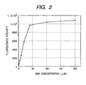
- DNA solutions of 0 ⁇ M, 2 ⁇ M , 5 ⁇ M, 10 ⁇ M, 20 ⁇ M, 40 ⁇ M, 100 ⁇ M and 200 ⁇ M (base pair concentration) were supplied in an amount of 50 picoliter into eight wells respectively, as in Example 7.
- 50 pl of a 10 ⁇ M EB solution was added to each well, and incubated as in Example 7.
- the fluorescent images from the fluorescent microscope were read into an ICCD camera (Hamamatsu Photonix C2400-87) and the light volume was quantitatively determined by an image processing devise (Hamamatsu Photonix Argus50).
- the signal amplification level of Argus50 was appropriately set.
- the results are shown in Fig. 2.
- Fig. 2 indicates that the reaction in the minute reaction site array of the present invention proceeded and detected quantitatively. At a certain ratio of DNA and EB, the fluorescence intensity reaches saturation.
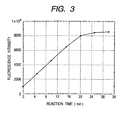
- Fig. 3 indicates that the reaction in the minute reaction site array of the present invention proceeded and detected quantitatively.
- the fluorescence intensity reaches the saturation due to the enzyme/substrate ratio.
- a minute reaction site array of about 1 cm ⁇ 1 cm was formed on a glass substrate in the same manner as in Example 1, except that the black matrix pattern was 5 ⁇ m in width and the film thickness was 4 ⁇ m, and there were contained 1,000,000 units of 5 ⁇ m ⁇ 5 ⁇ m square wells. Then, a solution of 10 ⁇ M rhodamine B was fed to each well using an ink-jet device in a checkered pattern. The precision of ejection positioning of the ink-jet device used is ⁇ 0.5 ⁇ m. Then, an aqueous solution of 10 ⁇ M amino-FITC was fed in an amount of 1 pl into each of the remaining wells from another ink-jet head.
- the present invention enables the preparation of a minute reaction site array suitable for the supply of the reaction species to conduct a large number of various kinds of reactions in a small region (for example, 1 cm ⁇ 1 cm) on a substrate.
- a minute reaction site array suitable for the supply of the reaction species to conduct a large number of various kinds of reactions in a small region (for example, 1 cm ⁇ 1 cm) on a substrate.
Landscapes
- Health & Medical Sciences (AREA)
- Life Sciences & Earth Sciences (AREA)
- Immunology (AREA)
- Chemical & Material Sciences (AREA)
- Engineering & Computer Science (AREA)
- Molecular Biology (AREA)
- Hematology (AREA)
- Biomedical Technology (AREA)
- Urology & Nephrology (AREA)
- Physics & Mathematics (AREA)
- Biochemistry (AREA)
- Microbiology (AREA)
- Pathology (AREA)
- Biotechnology (AREA)
- Food Science & Technology (AREA)
- Medicinal Chemistry (AREA)
- General Physics & Mathematics (AREA)
- Analytical Chemistry (AREA)
- Cell Biology (AREA)
- General Health & Medical Sciences (AREA)
- Organic Chemistry (AREA)
- Chemical Kinetics & Catalysis (AREA)
- Apparatus Associated With Microorganisms And Enzymes (AREA)
- Measuring Or Testing Involving Enzymes Or Micro-Organisms (AREA)
- Investigating Or Analyzing Non-Biological Materials By The Use Of Chemical Means (AREA)
- Physical Or Chemical Processes And Apparatus (AREA)
Claims (75)
- Verfahren zum Herstellen eines Reaktionsstellenarrays, umfassend:mehrere für die Aufnahme von Flüssigkeit ausgelegte Reaktionsstellen (3) zum Durchführen einer Reaktion zwischen zwei oder mehr Arten von Substanzen in einem flüssigen Medium, wobei jede der Reaktionsstellen (3) sich zusammensetzt aus einem ersten Bereich (4), der durch einen gegenüber dem ersten Bereich (4) erhöhten zweiten Bereich (2) von anderen Reaktionsstellen getrennt ist, wobei das Verfahren die Schritte umfasst:dadurch gekennzeichnet, dassBereitstellen eines Trägers (1); undErzeugen eines gegenüber der Trägeroberfläche erhöhten Matrixmusters, um mehrere erste Bereiche (4) zu definieren, welche durch das Matrixmuster des zweiten Bereichs (2) voneinander getrennt sind;
entweder:(i) die Oberfläche jedes der ersten Bereiche (4) hydrophil und die Oberfläche des zweiten Bereichs (2) hydrophob ist; oder:(ii) die Oberfläche jedes der ersten Bereiche (4) lipophil und die Oberfläche des zweiten Bereichs (2) nicht-lipophil ist; unddass der Träger transparent und der zweite Bereich schwarz gefärbt ist. - Verfahren nach Anspruch 1, wobei
die freiliegende Oberfläche des Trägers hydrophil und die Oberfläche des Matrixmusters hydrophob ist, wobei das Matrixmuster aus einem Harzmaterial erzeugt wird. - Verfahren nach Anspruch 1, wobei
das Matrixmuster durch ein Photolithographieverfahren erzeugt wird. - Verfahren nach Anspruch 3, wobei
das Photolithographieverfahren die folgenden Schritte aufweist:Erzeugen einer Harzschicht auf der Trägeroberfläche;Ausbilden einer Photoresistschicht auf der Harzschicht;Bestrahlen der Photoresistschicht mit Licht, so dass ein dem Matrixmuster entsprechendes Muster erzeugt wird;Entwickeln der bestrahlten Photoresistschicht;Versehen der Harzschicht mit einem Muster, wobei die Photoresistschicht als Maske verwendet wird; undErzeugen des Matrixmusters durch Entfernen der Photoresistschicht. - Verfahren nach Anspruch 3, wobei
das Photolithographieverfahren die folgenden Schritte aufweist:Erzeugen einer lichtempfindlichen Harzschicht auf der Trägeroberfläche;Bestrahlen der lichtempfindlichen Harzschicht mit Licht, so dass ein dem Matrixmuster entsprechendes Muster erzeugt wird;Entwickeln der lichtempfindlichen Harzschicht, so dass das Matrixmuster erzeugt wird. - Verfahren nach Anspruch 5, wobei
das aus der lichtempfindlichen Harzschicht erzeugte Matrixmuster nach seiner Entwicklung des weiteren einem Warmtrocknungsverfahren (baking process) unterzogen wird, so dass dessen Wasserabweisungsvermögen verbessert wird. - Verfahren nach Anspruch 1, bei dem die Trägeroberfläche hydrophil ist,
wobei
die den ersten Bereich umfassende Trägeroberfläche einem Ätzvorgang unterzogen wird, bei welchem das Matrixmuster als Maske verwendet wird, so dass die Hydrophilie des ersten Bereichs verbessert wird. - Verfahren nach Anspruch 1, wobei
das Matrixmuster opak ist. - Verfahren nach Anspruch 1, wobei
die Höhe des Matrixmusters 1 bis 20 µm beträgt. - Verfahren nach Anspruch 1, wobei
der Abstand zwischen den aneinander angrenzenden ersten Bereichen das 1/2- bis 2fache einer maximalen Länge des ersten Bereichs beträgt. - Vorrichtung in Form eines Reaktionsstellenarrays zum Durchführen einer Reaktion zwischen zwei oder mehr Arten von Substanzen in einem flüssigen Medium, umfassend: einen Träger (1) und Reaktionsstellen (3), die für die Aufnahme von Flüssigkeit ausgelegt sind, wobei jede der Reaktionsstellen (3) sich zusammensetzt aus einem ersten Bereich (4), der von anderen Reaktionsstellen durch einen zweiten Bereich (2), der gegenüber dem ersten Bereich erhöht ist, getrennt ist;
dadurch gekennzeichnet, dass
entweder:(i) die Oberfläche jedes der ersten Bereiche (4) hydrophil und die Oberfläche des zweiten Bereichs (2) hydrophob ist;
oder:(ii) die Oberfläche jedes der ersten Bereiche (4) lipophil und die Oberfläche des zweiten Bereichs (2) nicht-lipophil ist; unddass der Träger transparent und der zweite Bereich schwarz gefärbt ist. - Vorrichtung nach Anspruch 11, wobei
die Dichte der Reaktionsstellen 102 Einheiten/cm2 oder mehr beträgt. - Vorrichtung nach Anspruch 11, wobei
der zweite Bereich (2) in einer Musterform auf der Oberfläche des Trägers ausgebildet ist. - Vorrichtung nach Anspruch 1 1 oder 13, wobei
die freiliegende Oberfläche des Trägers hydrophil und die Oberfläche des Matrixmusters hydrophob ist, wobei der zweite Bereich sich zusammensetzt aus einem Harzmaterial. - Vorrichtung nach Anspruch 13, wobei
der zweite Bereich durch ein Photolithographieverfahren erzeugt ist. - Vorrichtung nach Anspruch 11, wobei
der erste Bereich transparent und der zweite Bereich opak ist. - Vorrichtung nach Anspruch 11, wobei
der zweite Bereich opak ist. - Vorrichtung nach Anspruch 11, wobei
eine maximale Länge des ersten Bereichs 200 µm oder weniger beträgt. - Vorrichtung nach Anspruch 11, wobei
der Abstand zwischen den zueinander benachbarten ersten Bereichen, die jedoch vom zweiten Bereich getrennt sind, im Bereich vom 1/2- bis 2fachen einer maximalen Länge des ersten Bereichs liegt. - Vorrichtung nach Anspruch 11, wobei
eine Höhe des zweiten Bereichs 1 µm bis 20 µm beträgt. - Verfahren zum Durchführen einer Reaktion zwischen zwei oder mehr Arten von Substanzen in einem flüssigen Medium, umfassend die Schritte:Bereitstellen eines Reaktionsstellenarrays, umfassend: mehrere für die Aufnahme von Flüssigkeit ausgelegte Reaktionsstellen (3), die sich zusammensetzen aus einem ersten Bereich (4), der durch einen zweiten Bereich, der gegenüber dem ersten Bereich erhöht ist, von anderen Reaktionsstellen getrennt ist, undAufbringen der Substanzen auf zumindest eine der Reaktionsstellen (3) und Reagierenlassen der Substanzen an den Stellen;wobei die Reaktion auf einer freiliegenden, den ersten Bereich (4) bildenden Oberfläche eines Trägers (1) erfolgt;
dadurch gekennzeichnet, dass
entweder:(i) die Oberfläche jedes ersten Bereichs (4) hydrophil und die Oberfläche des zweiten Bereichs (2) hydrophob ist; oder:(ii) die Oberfläche jedes ersten Bereichs (4) lipophil und die Oberfläche des zweiten Bereichs (2) nicht-lipophil ist; und dass der Träger transparent und der zweite Bereich schwarz gefärbt ist. - Verfahren nach Anspruch 21, wobei
das an einer Reaktionsstelle gehaltene flüssige Medium von der Oberseite des zweiten Bereichs aus anschwellen (swelled from the top of ...) gelassen wird. - Verfahren nach Anspruch 21 oder 22, wobei
die Dichte der Reaktionsstellen 102 Einheiten/cm2 oder mehr beträgt. - Verfahren nach Anspruch 21 oder 22, wobei
der zweite Bereich (2) in einer Musterform auf der Oberfläche des Trägers ausgebildet wird. - Verfahren nach einem der Ansprüche 21, 22 oder 24, bei dem die freiliegende Oberfläche des Trägers hydrophil und die Oberfläche des Matrixmusters hydrophob ist, wobei
der zweite Bereich aus einem Harzmaterial zusammengesetzt wird. - Verfahren nach einem der Ansprüche 21, 22 oder 24, wobei
der zweite Bereich durch ein Photolithographieverfahren erzeugt wird. - Verfahren nach Anspruch 21 oder 22, wobei
der erste Bereich transparent und der zweite Bereich opak ist. - Verfahren nach Anspruch 24, wobei
der zweite Bereich opak ist. - Verfahren nach Anspruch 21 oder 22, wobei
eine maximale Länge des ersten Bereichs 200 µm oder weniger beträgt. - Verfahren nach Anspruch 21 oder 22, wobei
der Abstand zwischen den zueinander benachbarten ersten Bereichen im Bereich vom 1/2- bis 2fachen der maximalen Länge von jenen ersten Bereichen liegt. - Verfahren nach Anspruch 21 oder 22, wobei
eine Höhe des zweiten Bereichs im Bereich von 1 bis 20 µm liegt. - Verfahren nach Anspruch 21 oder 22, wobei
bei den zwei oder mehr Substanzen solche eingeschlossen sind, welche zueinander als ein Ligand und ein Rezeptor in Beziehung stehen. - Verfahren nach Anspruch 21 oder 22, wobei
bei den zwei oder mehr Substanzen Oligopeptide oder Polypeptide mit einer bestimmten Aminosäuresequenz eingeschlossen sind. - Verfahren nach Anspruch 21 oder 22, wobei
bei den zwei oder mehr Substanzen Proteine eingeschlossen sind. - Verfahren nach Anspruch 34, wobei
die Proteine Antikörper sind. - Verfahren nach Anspruch 35, wobei
die Proteine Antigene sind. - Verfahren nach Anspruch 21 oder 22, wobei
bei den zwei oder mehr Substanzen Enzyme eingeschlossen sind. - Verfahren nach Anspruch 21 oder 22, wobei
bei den zwei oder mehr Substanzen einsträngige Nucleinsäuren oder modifizierte Nucleinsäuren mit einer bestimmten Basensequenz eingeschlossen sind. - Verfahren nach Anspruch 38, wobei
die Nucleinsäuren Oligonucleotide und Polynucleotide sind. - Verfahren nach Anspruch 38, wobei
die Nucleinsäure DNA ist. - Verfahren nach Anspruch 38, wobei
die Nucleinsäure RNA ist. - Verfahren nach Anspruch 38, wobei
die modifizierte Nucleinsäure Protein-Nucleinsäure (PNA: Protein-Nucleinsäure) ist. - Verfahren nach Anspruch 21 oder 22, wobei
das Zuführen der Substanzen zum Reaktionsstellenarray unter Anwendung eines Tintenstrahlverfahrens erfolgt. - Verfahren nach Anspruch 43, wobei
das Zuführen der Substanzen zum Reaktionsstellenarray unter Anwendung eines Blasenstrahlverfahrens erfolgt. - Verfahren nach Anspruch 43, wobei
das Zuführen der Substanzen zum Reaktionsstellenarray unter Anwendung eines Piezostrahlverfahrens erfolgt. - Verfahren zum mengenmäßigen Erfassen einer ersten Substanz, die in einer Probenflüssigkeit enthalten ist, umfassend die Schritte:a) Bereitstellen eines Reaktionsstellenarrays, umfassend mehrere Reaktionsstellen (3), die für die Aufnahme von Flüssigkeit ausgelegt sind, wobei jede der Reaktionsstellen sich zusammensetzt aus einem ersten Bereich (4), der durch einen gegenüber dem ersten Bereich erhöhten zweiten Bereich (2) von anderen Reaktionsstellen getrennt ist;b) Zuführen der Probenflüssigkeit zur Reaktionsstelle;c) Zuführen zu der Reaktionsstelle eines Reagenz, das für ein nachweisbares und mengenmäßig erfassbares Signal sorgt, wenn es in Wechselwirkung mit den ersten Substanzen tritt, so dass die mengenmäßige Erfassung der ersten Substanz möglich ist; undd) quantitatives Erfassen des Signals;wobei die Reaktion auf einer freiliegenden Oberfläche eines Trägers (1), welche den ersten Bereich (4) bildet, erfolgt;
dadurch gekennzeichnet, dass
entweder:(i) die Oberfläche jedes der ersten Bereiche (4) hydrophil und die Oberfläche des zweiten Bereichs (2) hydrophob ist;
oder:(ii) die Oberfläche jedes der ersten Bereiche (4) lipophil und die Oberfläche des zweiten Bereichs (2) nicht-lipophil ist; unddass der Träger transparent und der zweite Bereich schwarz gefärbt ist. - Verfahren nach Anspruch 46, wobei
das flüssige Medium, das an der Reaktionsstelle gehalten wird, von der Oberseite des zweiten Bereichs aus anschwellen gelassen wird. - Verfahren nach Anspruch 46 oder 47, wobei
der Schritt c) ein Verfahren einschließt, bei dem jeder Reaktionsstelle ein flüssiges Medium zugeführt wird, welches eine sich an die erste Substanz bindende zweite Substanz und das Reagenz enthält, und letzteres mit einem Komplex aus der ersten und der zweiten Substanz in Wechselwirkung tritt. - Verfahren nach Anspruch 48, wobei
jeder Reaktionsstelle unterschiedliche Arten von Substanzen als die zweiten Substanzen zugeführt werden. - Verfahren nach Anspruch 46 oder 47, wobei
die Dichte der Reaktionsstellen 102 Einheiten/cm2 oder mehr beträgt. - Verfahren nach Anspruch 46 oder 47, wobei
der zweite Bereich in einer Musterform auf der Oberfläche des Trägers ausgebildet ist. - Verfahren nach einem der Ansprüche 46, 47 oder 51, bei dem die freiliegende Oberfläche des Trägers hydrophil und die Oberfläche des Matrixmusters hydrophob ist, wobei
der zweite Bereich sich aus einem Matrixmaterial zusammensetzt. - Verfahren nach einem der Ansprüche 46, 47, 51 oder 52, wobei
der zweite Bereich durch ein Photolithographieverfahren erzeugt wird. - Verfahren nach Anspruch 46 oder 47, wobei
der erste Bereich transparent und der zweite Bereich opak ist. - Verfahren nach Anspruch 46 oder 47, wobei
der zweite Bereich opak ist. - Verfahren nach Anspruch 47, wobei
eine maximale Länge des ersten Bereichs 200 µm oder weniger beträgt. - Verfahren nach Anspruch 46 oder 47, wobei
ein Abstand zwischen den ersten Bereichen, die einander zugekehrt sind, jedoch durch den zweiten Bereich getrennt sind, im Bereich vom 1/2- bis 2fachen der maximalen Länge des ersten Bereichs liegt. - Verfahren nach Anspruch 46 oder 47, wobei
die Höhe des zweiten Bereichs 20 µm oder weniger beträgt. - Verfahren nach Anspruch 46 oder 47, wobei
das Reagenz in der Probenflüssigkeit enthalten ist. - Verfahren nach Anspruch 48, wobei
das Reagenz enthalten ist in einem flüssigen Medium, das die zweite Substanz enthält. - Verfahren nach Anspruch 48, wobei
die erste Substanz und die zweite Substanz zueinander als ein Ligand und ein Rezeptor in Beziehung stehen. - Verfahren nach Anspruch 48, wobei
die erste Substanz und/oder die zweite Substanz ein Oligonucleotid oder Polypeptid mit einer bestimmten Aminosäuresequenz sind/ist. - Verfahren nach Anspruch 62, wobei
die erste Substanz und/oder die zweite Substanz ein Protein sind/ist. - Verfahren nach Anspruch 63, wobei
das Protein ein Antikörper ist. - Verfahren nach Anspruch 63, wobei
das Protein ein Antigen ist. - Verfahren nach Anspruch 48, wobei
die erste Substanz und/oder die zweite Substanz ein Enzym sind/ist. - Verfahren nach Anspruch 48, wobei
die erste Substanz und/oder die zweite Substanz eine einsträngige Nucleinsäure oder eine modifizierte Nucleinsäure mit einer bestimmten Basensequenz sind/ist. - Verfahren nach Anspruch 67, wobei
die Nucleinsäure ein Oligonucleotid oder ein Polynucleotid ist. - Verfahren nach Anspruch 67, wobei
die Nucleinsäure eine DNA ist. - Verfahren nach Anspruch 67, wobei
die Nucleinsäure eine RNA ist. - Verfahren nach Anspruch 67, wobei
die Nucleinsäure eine Protein-Nucleinsäure (PNA) ist. - Verfahren nach Anspruch 46 oder 47, wobei
das Zuführen der Probe und/oder des Reagenz zur Reaktionsstelle durch ein Tintenstrahlverfahren erfolgt. - Verfahren nach Anspruch 48, wobei
das Zuführen eines flüssigen Mediums, das die zweite Substanz enthält, zur Reaktionsstelle durch ein Tintenstrahlverfahren erfolgt. - Verfahren nach Anspruch 72 oder 73, wobei
das Tintenstrahlverfahren ein Blasenstrahlverfahren ist. - Verfahren nach Anspruch 72 oder 73, wobei
das Tintenstrahlverfahren ein Piezostrahlverfahren ist.
Applications Claiming Priority (3)
| Application Number | Priority Date | Filing Date | Title |
|---|---|---|---|
| JP20783897 | 1997-08-01 | ||
| JP20783897 | 1997-08-01 | ||
| JP207838/97 | 1997-08-01 |
Publications (3)
| Publication Number | Publication Date |
|---|---|
| EP0895083A2 EP0895083A2 (de) | 1999-02-03 |
| EP0895083A3 EP0895083A3 (de) | 1999-08-11 |
| EP0895083B1 true EP0895083B1 (de) | 2009-09-23 |
Family
ID=16546369
Family Applications (1)
| Application Number | Title | Priority Date | Filing Date |
|---|---|---|---|
| EP98306110A Expired - Lifetime EP0895083B1 (de) | 1997-08-01 | 1998-07-31 | Reaktionsstellenarray, Verfahren zu seiner Herstellung, Reaktionsverfahren unter seiner Verwendung und quantitatives Bestimmungsverfahren für eine Substanz in einer Probelösung unter seiner Verwendung |
Country Status (5)
| Country | Link |
|---|---|
| US (2) | US6548020B2 (de) |
| EP (1) | EP0895083B1 (de) |
| AT (1) | ATE443866T1 (de) |
| CA (1) | CA2244414A1 (de) |
| DE (1) | DE69841171D1 (de) |
Families Citing this family (31)
| Publication number | Priority date | Publication date | Assignee | Title |
|---|---|---|---|---|
| FR2798675B1 (fr) * | 1999-09-16 | 2004-02-27 | Centre Nat Rech Scient | Procede et dispositif de fabrication d'un support porteur d'une pluralite de sequences polynucleotidiques et/ou peptidiques differentes |
| KR100792021B1 (ko) | 2000-03-30 | 2008-01-04 | 가부시키가이샤 에바라 세이사꾸쇼 | 반응성 탐식자 칩 및 그 제조방법 |
| JP4147234B2 (ja) * | 2004-09-27 | 2008-09-10 | キヤノン株式会社 | 吐出用液体、吐出方法、カートリッジ及び吐出装置 |
| AU2000275323A1 (en) * | 2000-09-27 | 2002-04-08 | Centre National De La Recherche Scientifique (C.N.R.S.) | Method and device for making a support bearing a plurality of different polynucleotide and/or peptide sequences |
| US7407746B2 (en) | 2001-02-08 | 2008-08-05 | Ngk Insulators, Ltd. | Biochip and method for producing the same |
| EP1377830A2 (de) * | 2001-02-16 | 2004-01-07 | Pepscan Systems B.V. | Anordnungen zur bestimmung der bindung von biomolekülen |
| US6852524B2 (en) | 2001-04-27 | 2005-02-08 | Canon Kabushiki Kaisha | Probe carrier, probe fixing carrier and method of manufacturing the same |
| EP1421217A2 (de) * | 2001-08-27 | 2004-05-26 | Zeptosens AG | Oberfläche zur immobilisierung von nukleinsäuren |
| KR100455293B1 (ko) * | 2002-05-15 | 2004-11-06 | 삼성전자주식회사 | 친수성 영역과 소수성 영역으로 구성되는 생물분자용어레이 판의 제조방법 |
| WO2005003375A2 (en) | 2003-01-29 | 2005-01-13 | 454 Corporation | Methods of amplifying and sequencing nucleic acids |
| CN100514065C (zh) * | 2003-08-27 | 2009-07-15 | 松下电器产业株式会社 | 微芯片及其制造方法以及使用微芯片的检查方法 |
| US20050208769A1 (en) * | 2004-03-19 | 2005-09-22 | Manish Sharma | Semiconductor structure |
| US20050233366A1 (en) * | 2004-04-16 | 2005-10-20 | Norihisa Mino | Sample-analyzing device and process for manufacturing the same |
| US20090042741A1 (en) * | 2004-05-06 | 2009-02-12 | Arizona Board Of Regents, Acting For And On Behalf Of Arizona State University | Microarray of three-dimensional heteropolymer microstructures and method therefor |
| JP4147235B2 (ja) * | 2004-09-27 | 2008-09-10 | キヤノン株式会社 | 吐出用液体、吐出方法、液滴化方法、液体吐出カートリッジ及び吐出装置 |
| US20060246467A1 (en) * | 2004-11-15 | 2006-11-02 | California Institute Of Technology | Biomarker sensors and method for multi-color imaging and processing of single-molecule life signatures |
| EP1877533A2 (de) * | 2005-04-18 | 2008-01-16 | Dsm Ip Assets B.V. | Biochip und verfahren zur herstellung eines biochips |
| JP4641476B2 (ja) * | 2005-09-15 | 2011-03-02 | キヤノン株式会社 | プローブアレイの製造装置 |
| US20070134784A1 (en) * | 2005-12-09 | 2007-06-14 | Halverson Kurt J | Microreplicated microarrays |
| CN101410709A (zh) * | 2006-03-28 | 2009-04-15 | 皇家飞利浦电子股份有限公司 | 具有光电探测器阵列和样品位点阵列的集成装置 |
| KR100834745B1 (ko) | 2006-12-20 | 2008-06-09 | 삼성전자주식회사 | 분석 친화적 레이아웃에 기반한 올리고머 프로브 어레이칩, 이의 제조에 사용되는 마스크 및 이의 혼성화 분석방법 |
| GB0807242D0 (en) | 2008-04-21 | 2008-05-28 | Renishaw Plc | Metrological scale |
| JP4667490B2 (ja) * | 2008-07-09 | 2011-04-13 | 三菱電機株式会社 | 加熱調理器 |
| US20110236261A1 (en) * | 2008-12-11 | 2011-09-29 | Koninklijke Philips Electronics N.V. | Sensing device for detecting target elements in a fluid |
| WO2011067234A2 (en) * | 2009-12-02 | 2011-06-09 | Roche Diagnostics Gmbh | Multiplexed microarray and method of fabricating thereof |
| US8753873B2 (en) | 2011-04-15 | 2014-06-17 | Roche Nimblegen, Inc. | Multiplexed microarray assembly and method for fabricating a multiplexed microarray |
| DE102013210138A1 (de) * | 2013-05-30 | 2014-12-04 | Boehringer Ingelheim Vetmedica Gmbh | Verfahren zum Erzeugen einer Vielzahl von Messbereichen auf einem Chip sowie Chip mit Messbereichen |
| KR20160073016A (ko) * | 2014-12-16 | 2016-06-24 | 삼성전자주식회사 | 광학분석용 구조체 및 광학분석용 구조체 제조용 잉크 조성물 |
| GB201520341D0 (en) * | 2015-11-18 | 2015-12-30 | Randox Lab Ltd And Randox Teoranta | Improvements relating to substrates for the attachment of molecules |
| JP7079196B2 (ja) | 2015-12-02 | 2022-06-01 | ベーリンガー インゲルハイム フェトメディカ ゲーエムベーハー | チップ上に複数の測定領域を作製するための方法、及び複数の測定領域を有するチップ |
| US20220397585A1 (en) * | 2019-12-26 | 2022-12-15 | Mgi Tech Co., Ltd. | Liquid transfer device and method, biochemical substance reaction device, and biochemical substance analysis device and method |
Family Cites Families (15)
| Publication number | Priority date | Publication date | Assignee | Title |
|---|---|---|---|---|
| US4000334A (en) * | 1971-07-15 | 1976-12-28 | Energy Conversion Devices, Inc. | Thermal imaging involving imagewise melting to form spaced apart globules |
| US5202231A (en) | 1987-04-01 | 1993-04-13 | Drmanac Radoje T | Method of sequencing of genomes by hybridization of oligonucleotide probes |
| GB8810400D0 (en) | 1988-05-03 | 1988-06-08 | Southern E | Analysing polynucleotide sequences |
| US5424186A (en) | 1989-06-07 | 1995-06-13 | Affymax Technologies N.V. | Very large scale immobilized polymer synthesis |
| US5143854A (en) | 1989-06-07 | 1992-09-01 | Affymax Technologies N.V. | Large scale photolithographic solid phase synthesis of polypeptides and receptor binding screening thereof |
| US5474796A (en) | 1991-09-04 | 1995-12-12 | Protogene Laboratories, Inc. | Method and apparatus for conducting an array of chemical reactions on a support surface |
| US5846708A (en) | 1991-11-19 | 1998-12-08 | Massachusetts Institiute Of Technology | Optical and electrical methods and apparatus for molecule detection |
| US5441894A (en) * | 1993-04-30 | 1995-08-15 | Abbott Laboratories | Device containing a light absorbing element for automated chemiluminescent immunoassays |
| JPH07179797A (ja) * | 1993-12-24 | 1995-07-18 | Canon Inc | バブルジェット用記録液およびそれを用いた記録方法 |
| US6015880A (en) | 1994-03-16 | 2000-01-18 | California Institute Of Technology | Method and substrate for performing multiple sequential reactions on a matrix |
| US5807522A (en) | 1994-06-17 | 1998-09-15 | The Board Of Trustees Of The Leland Stanford Junior University | Methods for fabricating microarrays of biological samples |
| US6121048A (en) * | 1994-10-18 | 2000-09-19 | Zaffaroni; Alejandro C. | Method of conducting a plurality of reactions |
| US5688642A (en) | 1994-12-01 | 1997-11-18 | The United States Of America As Represented By The Secretary Of The Navy | Selective attachment of nucleic acid molecules to patterned self-assembled surfaces |
| JPH0954093A (ja) * | 1995-08-18 | 1997-02-25 | Adtec Kk | 抗原や抗体の固相方法 |
| US6143496A (en) * | 1997-04-17 | 2000-11-07 | Cytonix Corporation | Method of sampling, amplifying and quantifying segment of nucleic acid, polymerase chain reaction assembly having nanoliter-sized sample chambers, and method of filling assembly |
-
1998
- 1998-07-31 CA CA002244414A patent/CA2244414A1/en not_active Abandoned
- 1998-07-31 DE DE69841171T patent/DE69841171D1/de not_active Expired - Lifetime
- 1998-07-31 EP EP98306110A patent/EP0895083B1/de not_active Expired - Lifetime
- 1998-07-31 US US09/126,856 patent/US6548020B2/en not_active Expired - Fee Related
- 1998-07-31 AT AT98306110T patent/ATE443866T1/de not_active IP Right Cessation
-
2003
- 2003-02-07 US US10/359,603 patent/US20030119179A1/en not_active Abandoned
Also Published As
| Publication number | Publication date |
|---|---|
| DE69841171D1 (de) | 2009-11-05 |
| ATE443866T1 (de) | 2009-10-15 |
| US6548020B2 (en) | 2003-04-15 |
| US20030119179A1 (en) | 2003-06-26 |
| EP0895083A2 (de) | 1999-02-03 |
| EP0895083A3 (de) | 1999-08-11 |
| CA2244414A1 (en) | 1999-02-01 |
| US20020150506A1 (en) | 2002-10-17 |
Similar Documents
| Publication | Publication Date | Title |
|---|---|---|
| EP0895083B1 (de) | Reaktionsstellenarray, Verfahren zu seiner Herstellung, Reaktionsverfahren unter seiner Verwendung und quantitatives Bestimmungsverfahren für eine Substanz in einer Probelösung unter seiner Verwendung | |
| JP3610231B2 (ja) | 反応場アレー、反応場アレーの製造方法、反応場アレーを用いた反応方法及び反応場アレーを用いた試料溶液中の物質の定量方法 | |
| EP0895082B1 (de) | "Bubble-jet" -Verfahren zur Probenaufgabe auf festen Trägern und zur Herstellung von Sondenarrays. | |
| Barbulovic-Nad et al. | Bio-microarray fabrication techniques—a review | |
| EP2113301B1 (de) | Herstellung von Mikrokugeln | |
| US6783735B2 (en) | Web material having wells for combinatorial applications | |
| CA2226662A1 (en) | Methods and systems for biological reagent placement | |
| CA2320810A1 (en) | Method of quality control in manufacturing processes | |
| US20070134699A1 (en) | Nano-scale ligand arrays on substrates for particle beam instruments and related methods | |
| US20030190612A1 (en) | Detecting method and detection substrate for use therein | |
| JP4378042B2 (ja) | 検体試料中の対象成分の検出方法、およびそれに用いる検出用基板 | |
| US6878523B2 (en) | Molecular interaction assays on a solid surface | |
| US20020057995A1 (en) | Microtiter plate | |
| JP4274561B2 (ja) | プローブアレイとその製造方法 | |
| JP2002065299A (ja) | 同時多項目多検体検査法 | |
| JP4208392B2 (ja) | プローブをインクジェット法で吐出させるための液体組成物 | |
| EP1188481A2 (de) | Mikrotiterplatte mit Öffnungen für Anwendungen in der kombinatorischen Chemie | |
| EP1245278A2 (de) | Bahnförmiges Material mit Mikroöffnungen für Anwendungen in der kombinatorischen Chemie | |
| US20060166218A1 (en) | Protective coating for array material deposition | |
| Ermantraut et al. | Generation of libraries by print technologies |
Legal Events
| Date | Code | Title | Description |
|---|---|---|---|
| PUAI | Public reference made under article 153(3) epc to a published international application that has entered the european phase |
Free format text: ORIGINAL CODE: 0009012 |
|
| AK | Designated contracting states |
Kind code of ref document: A2 Designated state(s): AT BE CH CY DE DK ES FI FR GB GR IE IT LI LU NL PT SE |
|
| AX | Request for extension of the european patent |
Free format text: AL;LT;LV;MK;RO;SI |
|
| PUAL | Search report despatched |
Free format text: ORIGINAL CODE: 0009013 |
|
| AK | Designated contracting states |
Kind code of ref document: A3 Designated state(s): AT BE CH CY DE DK ES FI FR GB GR IE IT LI LU MC NL PT SE |
|
| AX | Request for extension of the european patent |
Free format text: AL;LT;LV;MK;RO;SI |
|
| 17P | Request for examination filed |
Effective date: 20000113 |
|
| AKX | Designation fees paid |
Free format text: AT BE CH CY DE DK ES FI FR GB GR IE IT LI LU NL PT SE |
|
| 17Q | First examination report despatched |
Effective date: 20020220 |
|
| GRAP | Despatch of communication of intention to grant a patent |
Free format text: ORIGINAL CODE: EPIDOSNIGR1 |
|
| GRAS | Grant fee paid |
Free format text: ORIGINAL CODE: EPIDOSNIGR3 |
|
| GRAA | (expected) grant |
Free format text: ORIGINAL CODE: 0009210 |
|
| AK | Designated contracting states |
Kind code of ref document: B1 Designated state(s): AT BE CH CY DE DK ES FI FR GB GR IE IT LI LU NL PT SE |
|
| REG | Reference to a national code |
Ref country code: GB Ref legal event code: FG4D |
|
| REG | Reference to a national code |
Ref country code: CH Ref legal event code: EP |
|
| REG | Reference to a national code |
Ref country code: IE Ref legal event code: FG4D |
|
| REF | Corresponds to: |
Ref document number: 69841171 Country of ref document: DE Date of ref document: 20091105 Kind code of ref document: P |
|
| PG25 | Lapsed in a contracting state [announced via postgrant information from national office to epo] |
Ref country code: SE Free format text: LAPSE BECAUSE OF FAILURE TO SUBMIT A TRANSLATION OF THE DESCRIPTION OR TO PAY THE FEE WITHIN THE PRESCRIBED TIME-LIMIT Effective date: 20090923 Ref country code: FI Free format text: LAPSE BECAUSE OF FAILURE TO SUBMIT A TRANSLATION OF THE DESCRIPTION OR TO PAY THE FEE WITHIN THE PRESCRIBED TIME-LIMIT Effective date: 20090923 |
|
| NLV1 | Nl: lapsed or annulled due to failure to fulfill the requirements of art. 29p and 29m of the patents act | ||
| PG25 | Lapsed in a contracting state [announced via postgrant information from national office to epo] |
Ref country code: PT Free format text: LAPSE BECAUSE OF FAILURE TO SUBMIT A TRANSLATION OF THE DESCRIPTION OR TO PAY THE FEE WITHIN THE PRESCRIBED TIME-LIMIT Effective date: 20100125 Ref country code: ES Free format text: LAPSE BECAUSE OF FAILURE TO SUBMIT A TRANSLATION OF THE DESCRIPTION OR TO PAY THE FEE WITHIN THE PRESCRIBED TIME-LIMIT Effective date: 20100103 |
|
| PG25 | Lapsed in a contracting state [announced via postgrant information from national office to epo] |
Ref country code: BE Free format text: LAPSE BECAUSE OF FAILURE TO SUBMIT A TRANSLATION OF THE DESCRIPTION OR TO PAY THE FEE WITHIN THE PRESCRIBED TIME-LIMIT Effective date: 20090923 Ref country code: AT Free format text: LAPSE BECAUSE OF FAILURE TO SUBMIT A TRANSLATION OF THE DESCRIPTION OR TO PAY THE FEE WITHIN THE PRESCRIBED TIME-LIMIT Effective date: 20090923 |
|
| PG25 | Lapsed in a contracting state [announced via postgrant information from national office to epo] |
Ref country code: NL Free format text: LAPSE BECAUSE OF FAILURE TO SUBMIT A TRANSLATION OF THE DESCRIPTION OR TO PAY THE FEE WITHIN THE PRESCRIBED TIME-LIMIT Effective date: 20090923 Ref country code: DK Free format text: LAPSE BECAUSE OF FAILURE TO SUBMIT A TRANSLATION OF THE DESCRIPTION OR TO PAY THE FEE WITHIN THE PRESCRIBED TIME-LIMIT Effective date: 20090923 |
|
| PLBE | No opposition filed within time limit |
Free format text: ORIGINAL CODE: 0009261 |
|
| STAA | Information on the status of an ep patent application or granted ep patent |
Free format text: STATUS: NO OPPOSITION FILED WITHIN TIME LIMIT |
|
| 26N | No opposition filed |
Effective date: 20100624 |
|
| PG25 | Lapsed in a contracting state [announced via postgrant information from national office to epo] |
Ref country code: GR Free format text: LAPSE BECAUSE OF FAILURE TO SUBMIT A TRANSLATION OF THE DESCRIPTION OR TO PAY THE FEE WITHIN THE PRESCRIBED TIME-LIMIT Effective date: 20091224 |
|
| REG | Reference to a national code |
Ref country code: CH Ref legal event code: PL |
|
| PG25 | Lapsed in a contracting state [announced via postgrant information from national office to epo] |
Ref country code: CH Free format text: LAPSE BECAUSE OF NON-PAYMENT OF DUE FEES Effective date: 20100731 Ref country code: LI Free format text: LAPSE BECAUSE OF NON-PAYMENT OF DUE FEES Effective date: 20100731 |
|
| PG25 | Lapsed in a contracting state [announced via postgrant information from national office to epo] |
Ref country code: IE Free format text: LAPSE BECAUSE OF NON-PAYMENT OF DUE FEES Effective date: 20100731 |
|
| PG25 | Lapsed in a contracting state [announced via postgrant information from national office to epo] |
Ref country code: CY Free format text: LAPSE BECAUSE OF FAILURE TO SUBMIT A TRANSLATION OF THE DESCRIPTION OR TO PAY THE FEE WITHIN THE PRESCRIBED TIME-LIMIT Effective date: 20090923 |
|
| PG25 | Lapsed in a contracting state [announced via postgrant information from national office to epo] |
Ref country code: LU Free format text: LAPSE BECAUSE OF NON-PAYMENT OF DUE FEES Effective date: 20100731 |
|
| PGFP | Annual fee paid to national office [announced via postgrant information from national office to epo] |
Ref country code: DE Payment date: 20140731 Year of fee payment: 17 |
|
| PGFP | Annual fee paid to national office [announced via postgrant information from national office to epo] |
Ref country code: FR Payment date: 20140728 Year of fee payment: 17 Ref country code: GB Payment date: 20140724 Year of fee payment: 17 |
|
| PGFP | Annual fee paid to national office [announced via postgrant information from national office to epo] |
Ref country code: IT Payment date: 20140702 Year of fee payment: 17 |
|
| REG | Reference to a national code |
Ref country code: DE Ref legal event code: R119 Ref document number: 69841171 Country of ref document: DE |
|
| GBPC | Gb: european patent ceased through non-payment of renewal fee |
Effective date: 20150731 |
|
| PG25 | Lapsed in a contracting state [announced via postgrant information from national office to epo] |
Ref country code: DE Free format text: LAPSE BECAUSE OF NON-PAYMENT OF DUE FEES Effective date: 20160202 Ref country code: IT Free format text: LAPSE BECAUSE OF NON-PAYMENT OF DUE FEES Effective date: 20150731 Ref country code: GB Free format text: LAPSE BECAUSE OF NON-PAYMENT OF DUE FEES Effective date: 20150731 |
|
| REG | Reference to a national code |
Ref country code: FR Ref legal event code: ST Effective date: 20160331 |
|
| PG25 | Lapsed in a contracting state [announced via postgrant information from national office to epo] |
Ref country code: FR Free format text: LAPSE BECAUSE OF NON-PAYMENT OF DUE FEES Effective date: 20150731 |