EP0895045A2 - Verfahren zur Luftzerlegung - Google Patents
Verfahren zur Luftzerlegung Download PDFInfo
- Publication number
- EP0895045A2 EP0895045A2 EP98113793A EP98113793A EP0895045A2 EP 0895045 A2 EP0895045 A2 EP 0895045A2 EP 98113793 A EP98113793 A EP 98113793A EP 98113793 A EP98113793 A EP 98113793A EP 0895045 A2 EP0895045 A2 EP 0895045A2
- Authority
- EP
- European Patent Office
- Prior art keywords
- heat exchanger
- liquid
- liquid fraction
- pressure
- tank
- Prior art date
- Legal status (The legal status is an assumption and is not a legal conclusion. Google has not performed a legal analysis and makes no representation as to the accuracy of the status listed.)
- Granted
Links
Images

Classifications
-
- F—MECHANICAL ENGINEERING; LIGHTING; HEATING; WEAPONS; BLASTING
- F25—REFRIGERATION OR COOLING; COMBINED HEATING AND REFRIGERATION SYSTEMS; HEAT PUMP SYSTEMS; MANUFACTURE OR STORAGE OF ICE; LIQUEFACTION SOLIDIFICATION OF GASES
- F25J—LIQUEFACTION, SOLIDIFICATION OR SEPARATION OF GASES OR GASEOUS OR LIQUEFIED GASEOUS MIXTURES BY PRESSURE AND COLD TREATMENT OR BY BRINGING THEM INTO THE SUPERCRITICAL STATE
- F25J3/00—Processes or apparatus for separating the constituents of gaseous or liquefied gaseous mixtures involving the use of liquefaction or solidification
- F25J3/02—Processes or apparatus for separating the constituents of gaseous or liquefied gaseous mixtures involving the use of liquefaction or solidification by rectification, i.e. by continuous interchange of heat and material between a vapour stream and a liquid stream
- F25J3/04—Processes or apparatus for separating the constituents of gaseous or liquefied gaseous mixtures involving the use of liquefaction or solidification by rectification, i.e. by continuous interchange of heat and material between a vapour stream and a liquid stream for air
- F25J3/04006—Providing pressurised feed air or process streams within or from the air fractionation unit
- F25J3/04078—Providing pressurised feed air or process streams within or from the air fractionation unit providing pressurized products by liquid compression and vaporisation with cold recovery, i.e. so-called internal compression
- F25J3/0409—Providing pressurised feed air or process streams within or from the air fractionation unit providing pressurized products by liquid compression and vaporisation with cold recovery, i.e. so-called internal compression of oxygen
-
- F—MECHANICAL ENGINEERING; LIGHTING; HEATING; WEAPONS; BLASTING
- F25—REFRIGERATION OR COOLING; COMBINED HEATING AND REFRIGERATION SYSTEMS; HEAT PUMP SYSTEMS; MANUFACTURE OR STORAGE OF ICE; LIQUEFACTION SOLIDIFICATION OF GASES
- F25J—LIQUEFACTION, SOLIDIFICATION OR SEPARATION OF GASES OR GASEOUS OR LIQUEFIED GASEOUS MIXTURES BY PRESSURE AND COLD TREATMENT OR BY BRINGING THEM INTO THE SUPERCRITICAL STATE
- F25J3/00—Processes or apparatus for separating the constituents of gaseous or liquefied gaseous mixtures involving the use of liquefaction or solidification
- F25J3/02—Processes or apparatus for separating the constituents of gaseous or liquefied gaseous mixtures involving the use of liquefaction or solidification by rectification, i.e. by continuous interchange of heat and material between a vapour stream and a liquid stream
- F25J3/04—Processes or apparatus for separating the constituents of gaseous or liquefied gaseous mixtures involving the use of liquefaction or solidification by rectification, i.e. by continuous interchange of heat and material between a vapour stream and a liquid stream for air
- F25J3/04006—Providing pressurised feed air or process streams within or from the air fractionation unit
- F25J3/04078—Providing pressurised feed air or process streams within or from the air fractionation unit providing pressurized products by liquid compression and vaporisation with cold recovery, i.e. so-called internal compression
- F25J3/04084—Providing pressurised feed air or process streams within or from the air fractionation unit providing pressurized products by liquid compression and vaporisation with cold recovery, i.e. so-called internal compression of nitrogen
-
- F—MECHANICAL ENGINEERING; LIGHTING; HEATING; WEAPONS; BLASTING
- F25—REFRIGERATION OR COOLING; COMBINED HEATING AND REFRIGERATION SYSTEMS; HEAT PUMP SYSTEMS; MANUFACTURE OR STORAGE OF ICE; LIQUEFACTION SOLIDIFICATION OF GASES
- F25J—LIQUEFACTION, SOLIDIFICATION OR SEPARATION OF GASES OR GASEOUS OR LIQUEFIED GASEOUS MIXTURES BY PRESSURE AND COLD TREATMENT OR BY BRINGING THEM INTO THE SUPERCRITICAL STATE
- F25J3/00—Processes or apparatus for separating the constituents of gaseous or liquefied gaseous mixtures involving the use of liquefaction or solidification
- F25J3/02—Processes or apparatus for separating the constituents of gaseous or liquefied gaseous mixtures involving the use of liquefaction or solidification by rectification, i.e. by continuous interchange of heat and material between a vapour stream and a liquid stream
- F25J3/04—Processes or apparatus for separating the constituents of gaseous or liquefied gaseous mixtures involving the use of liquefaction or solidification by rectification, i.e. by continuous interchange of heat and material between a vapour stream and a liquid stream for air
- F25J3/04006—Providing pressurised feed air or process streams within or from the air fractionation unit
- F25J3/04078—Providing pressurised feed air or process streams within or from the air fractionation unit providing pressurized products by liquid compression and vaporisation with cold recovery, i.e. so-called internal compression
- F25J3/04103—Providing pressurised feed air or process streams within or from the air fractionation unit providing pressurized products by liquid compression and vaporisation with cold recovery, i.e. so-called internal compression using solely hydrostatic liquid head
-
- F—MECHANICAL ENGINEERING; LIGHTING; HEATING; WEAPONS; BLASTING
- F25—REFRIGERATION OR COOLING; COMBINED HEATING AND REFRIGERATION SYSTEMS; HEAT PUMP SYSTEMS; MANUFACTURE OR STORAGE OF ICE; LIQUEFACTION SOLIDIFICATION OF GASES
- F25J—LIQUEFACTION, SOLIDIFICATION OR SEPARATION OF GASES OR GASEOUS OR LIQUEFIED GASEOUS MIXTURES BY PRESSURE AND COLD TREATMENT OR BY BRINGING THEM INTO THE SUPERCRITICAL STATE
- F25J3/00—Processes or apparatus for separating the constituents of gaseous or liquefied gaseous mixtures involving the use of liquefaction or solidification
- F25J3/02—Processes or apparatus for separating the constituents of gaseous or liquefied gaseous mixtures involving the use of liquefaction or solidification by rectification, i.e. by continuous interchange of heat and material between a vapour stream and a liquid stream
- F25J3/04—Processes or apparatus for separating the constituents of gaseous or liquefied gaseous mixtures involving the use of liquefaction or solidification by rectification, i.e. by continuous interchange of heat and material between a vapour stream and a liquid stream for air
- F25J3/04151—Purification and (pre-)cooling of the feed air; recuperative heat-exchange with product streams
- F25J3/04187—Cooling of the purified feed air by recuperative heat-exchange; Heat-exchange with product streams
- F25J3/04193—Division of the main heat exchange line in consecutive sections having different functions
- F25J3/042—Division of the main heat exchange line in consecutive sections having different functions having an intermediate feed connection
-
- F—MECHANICAL ENGINEERING; LIGHTING; HEATING; WEAPONS; BLASTING
- F25—REFRIGERATION OR COOLING; COMBINED HEATING AND REFRIGERATION SYSTEMS; HEAT PUMP SYSTEMS; MANUFACTURE OR STORAGE OF ICE; LIQUEFACTION SOLIDIFICATION OF GASES
- F25J—LIQUEFACTION, SOLIDIFICATION OR SEPARATION OF GASES OR GASEOUS OR LIQUEFIED GASEOUS MIXTURES BY PRESSURE AND COLD TREATMENT OR BY BRINGING THEM INTO THE SUPERCRITICAL STATE
- F25J3/00—Processes or apparatus for separating the constituents of gaseous or liquefied gaseous mixtures involving the use of liquefaction or solidification
- F25J3/02—Processes or apparatus for separating the constituents of gaseous or liquefied gaseous mixtures involving the use of liquefaction or solidification by rectification, i.e. by continuous interchange of heat and material between a vapour stream and a liquid stream
- F25J3/04—Processes or apparatus for separating the constituents of gaseous or liquefied gaseous mixtures involving the use of liquefaction or solidification by rectification, i.e. by continuous interchange of heat and material between a vapour stream and a liquid stream for air
- F25J3/04151—Purification and (pre-)cooling of the feed air; recuperative heat-exchange with product streams
- F25J3/04187—Cooling of the purified feed air by recuperative heat-exchange; Heat-exchange with product streams
- F25J3/0423—Subcooling of liquid process streams
-
- F—MECHANICAL ENGINEERING; LIGHTING; HEATING; WEAPONS; BLASTING
- F25—REFRIGERATION OR COOLING; COMBINED HEATING AND REFRIGERATION SYSTEMS; HEAT PUMP SYSTEMS; MANUFACTURE OR STORAGE OF ICE; LIQUEFACTION SOLIDIFICATION OF GASES
- F25J—LIQUEFACTION, SOLIDIFICATION OR SEPARATION OF GASES OR GASEOUS OR LIQUEFIED GASEOUS MIXTURES BY PRESSURE AND COLD TREATMENT OR BY BRINGING THEM INTO THE SUPERCRITICAL STATE
- F25J3/00—Processes or apparatus for separating the constituents of gaseous or liquefied gaseous mixtures involving the use of liquefaction or solidification
- F25J3/02—Processes or apparatus for separating the constituents of gaseous or liquefied gaseous mixtures involving the use of liquefaction or solidification by rectification, i.e. by continuous interchange of heat and material between a vapour stream and a liquid stream
- F25J3/04—Processes or apparatus for separating the constituents of gaseous or liquefied gaseous mixtures involving the use of liquefaction or solidification by rectification, i.e. by continuous interchange of heat and material between a vapour stream and a liquid stream for air
- F25J3/04151—Purification and (pre-)cooling of the feed air; recuperative heat-exchange with product streams
- F25J3/04187—Cooling of the purified feed air by recuperative heat-exchange; Heat-exchange with product streams
- F25J3/04236—Integration of different exchangers in a single core, so-called integrated cores
-
- F—MECHANICAL ENGINEERING; LIGHTING; HEATING; WEAPONS; BLASTING
- F25—REFRIGERATION OR COOLING; COMBINED HEATING AND REFRIGERATION SYSTEMS; HEAT PUMP SYSTEMS; MANUFACTURE OR STORAGE OF ICE; LIQUEFACTION SOLIDIFICATION OF GASES
- F25J—LIQUEFACTION, SOLIDIFICATION OR SEPARATION OF GASES OR GASEOUS OR LIQUEFIED GASEOUS MIXTURES BY PRESSURE AND COLD TREATMENT OR BY BRINGING THEM INTO THE SUPERCRITICAL STATE
- F25J3/00—Processes or apparatus for separating the constituents of gaseous or liquefied gaseous mixtures involving the use of liquefaction or solidification
- F25J3/02—Processes or apparatus for separating the constituents of gaseous or liquefied gaseous mixtures involving the use of liquefaction or solidification by rectification, i.e. by continuous interchange of heat and material between a vapour stream and a liquid stream
- F25J3/04—Processes or apparatus for separating the constituents of gaseous or liquefied gaseous mixtures involving the use of liquefaction or solidification by rectification, i.e. by continuous interchange of heat and material between a vapour stream and a liquid stream for air
- F25J3/04406—Processes or apparatus for separating the constituents of gaseous or liquefied gaseous mixtures involving the use of liquefaction or solidification by rectification, i.e. by continuous interchange of heat and material between a vapour stream and a liquid stream for air using a dual pressure main column system
- F25J3/04412—Processes or apparatus for separating the constituents of gaseous or liquefied gaseous mixtures involving the use of liquefaction or solidification by rectification, i.e. by continuous interchange of heat and material between a vapour stream and a liquid stream for air using a dual pressure main column system in a classical double column flowsheet, i.e. with thermal coupling by a main reboiler-condenser in the bottom of low pressure respectively top of high pressure column
-
- F—MECHANICAL ENGINEERING; LIGHTING; HEATING; WEAPONS; BLASTING
- F25—REFRIGERATION OR COOLING; COMBINED HEATING AND REFRIGERATION SYSTEMS; HEAT PUMP SYSTEMS; MANUFACTURE OR STORAGE OF ICE; LIQUEFACTION SOLIDIFICATION OF GASES
- F25J—LIQUEFACTION, SOLIDIFICATION OR SEPARATION OF GASES OR GASEOUS OR LIQUEFIED GASEOUS MIXTURES BY PRESSURE AND COLD TREATMENT OR BY BRINGING THEM INTO THE SUPERCRITICAL STATE
- F25J3/00—Processes or apparatus for separating the constituents of gaseous or liquefied gaseous mixtures involving the use of liquefaction or solidification
- F25J3/02—Processes or apparatus for separating the constituents of gaseous or liquefied gaseous mixtures involving the use of liquefaction or solidification by rectification, i.e. by continuous interchange of heat and material between a vapour stream and a liquid stream
- F25J3/04—Processes or apparatus for separating the constituents of gaseous or liquefied gaseous mixtures involving the use of liquefaction or solidification by rectification, i.e. by continuous interchange of heat and material between a vapour stream and a liquid stream for air
- F25J3/04763—Start-up or control of the process; Details of the apparatus used
- F25J3/04769—Operation, control and regulation of the process; Instrumentation within the process
- F25J3/04812—Different modes, i.e. "runs" of operation
- F25J3/04824—Stopping of the process, e.g. defrosting or deriming; Back-up procedures
-
- F—MECHANICAL ENGINEERING; LIGHTING; HEATING; WEAPONS; BLASTING
- F25—REFRIGERATION OR COOLING; COMBINED HEATING AND REFRIGERATION SYSTEMS; HEAT PUMP SYSTEMS; MANUFACTURE OR STORAGE OF ICE; LIQUEFACTION SOLIDIFICATION OF GASES
- F25J—LIQUEFACTION, SOLIDIFICATION OR SEPARATION OF GASES OR GASEOUS OR LIQUEFIED GASEOUS MIXTURES BY PRESSURE AND COLD TREATMENT OR BY BRINGING THEM INTO THE SUPERCRITICAL STATE
- F25J3/00—Processes or apparatus for separating the constituents of gaseous or liquefied gaseous mixtures involving the use of liquefaction or solidification
- F25J3/02—Processes or apparatus for separating the constituents of gaseous or liquefied gaseous mixtures involving the use of liquefaction or solidification by rectification, i.e. by continuous interchange of heat and material between a vapour stream and a liquid stream
- F25J3/04—Processes or apparatus for separating the constituents of gaseous or liquefied gaseous mixtures involving the use of liquefaction or solidification by rectification, i.e. by continuous interchange of heat and material between a vapour stream and a liquid stream for air
- F25J3/04763—Start-up or control of the process; Details of the apparatus used
- F25J3/04769—Operation, control and regulation of the process; Instrumentation within the process
- F25J3/04812—Different modes, i.e. "runs" of operation
- F25J3/04836—Variable air feed, i.e. "load" or product demand during specified periods, e.g. during periods with high respectively low power costs
-
- F—MECHANICAL ENGINEERING; LIGHTING; HEATING; WEAPONS; BLASTING
- F25—REFRIGERATION OR COOLING; COMBINED HEATING AND REFRIGERATION SYSTEMS; HEAT PUMP SYSTEMS; MANUFACTURE OR STORAGE OF ICE; LIQUEFACTION SOLIDIFICATION OF GASES
- F25J—LIQUEFACTION, SOLIDIFICATION OR SEPARATION OF GASES OR GASEOUS OR LIQUEFIED GASEOUS MIXTURES BY PRESSURE AND COLD TREATMENT OR BY BRINGING THEM INTO THE SUPERCRITICAL STATE
- F25J3/00—Processes or apparatus for separating the constituents of gaseous or liquefied gaseous mixtures involving the use of liquefaction or solidification
- F25J3/02—Processes or apparatus for separating the constituents of gaseous or liquefied gaseous mixtures involving the use of liquefaction or solidification by rectification, i.e. by continuous interchange of heat and material between a vapour stream and a liquid stream
- F25J3/04—Processes or apparatus for separating the constituents of gaseous or liquefied gaseous mixtures involving the use of liquefaction or solidification by rectification, i.e. by continuous interchange of heat and material between a vapour stream and a liquid stream for air
- F25J3/04763—Start-up or control of the process; Details of the apparatus used
- F25J3/04866—Construction and layout of air fractionation equipments, e.g. valves, machines
- F25J3/04872—Vertical layout of cold equipments within in the cold box, e.g. columns, heat exchangers etc.
- F25J3/04878—Side by side arrangement of multiple vessels in a main column system, wherein the vessels are normally mounted one upon the other or forming different sections of the same column
-
- F—MECHANICAL ENGINEERING; LIGHTING; HEATING; WEAPONS; BLASTING
- F25—REFRIGERATION OR COOLING; COMBINED HEATING AND REFRIGERATION SYSTEMS; HEAT PUMP SYSTEMS; MANUFACTURE OR STORAGE OF ICE; LIQUEFACTION SOLIDIFICATION OF GASES
- F25J—LIQUEFACTION, SOLIDIFICATION OR SEPARATION OF GASES OR GASEOUS OR LIQUEFIED GASEOUS MIXTURES BY PRESSURE AND COLD TREATMENT OR BY BRINGING THEM INTO THE SUPERCRITICAL STATE
- F25J3/00—Processes or apparatus for separating the constituents of gaseous or liquefied gaseous mixtures involving the use of liquefaction or solidification
- F25J3/02—Processes or apparatus for separating the constituents of gaseous or liquefied gaseous mixtures involving the use of liquefaction or solidification by rectification, i.e. by continuous interchange of heat and material between a vapour stream and a liquid stream
- F25J3/04—Processes or apparatus for separating the constituents of gaseous or liquefied gaseous mixtures involving the use of liquefaction or solidification by rectification, i.e. by continuous interchange of heat and material between a vapour stream and a liquid stream for air
- F25J3/04763—Start-up or control of the process; Details of the apparatus used
- F25J3/04866—Construction and layout of air fractionation equipments, e.g. valves, machines
- F25J3/04951—Arrangements of multiple air fractionation units or multiple equipments fulfilling the same process step, e.g. multiple trains in a network
- F25J3/04963—Arrangements of multiple air fractionation units or multiple equipments fulfilling the same process step, e.g. multiple trains in a network and inter-connecting equipment within or downstream of the fractionation unit(s)
-
- F—MECHANICAL ENGINEERING; LIGHTING; HEATING; WEAPONS; BLASTING
- F25—REFRIGERATION OR COOLING; COMBINED HEATING AND REFRIGERATION SYSTEMS; HEAT PUMP SYSTEMS; MANUFACTURE OR STORAGE OF ICE; LIQUEFACTION SOLIDIFICATION OF GASES
- F25J—LIQUEFACTION, SOLIDIFICATION OR SEPARATION OF GASES OR GASEOUS OR LIQUEFIED GASEOUS MIXTURES BY PRESSURE AND COLD TREATMENT OR BY BRINGING THEM INTO THE SUPERCRITICAL STATE
- F25J2235/00—Processes or apparatus involving steps for increasing the pressure or for conveying of liquid process streams
- F25J2235/42—Processes or apparatus involving steps for increasing the pressure or for conveying of liquid process streams the fluid being nitrogen
-
- F—MECHANICAL ENGINEERING; LIGHTING; HEATING; WEAPONS; BLASTING
- F25—REFRIGERATION OR COOLING; COMBINED HEATING AND REFRIGERATION SYSTEMS; HEAT PUMP SYSTEMS; MANUFACTURE OR STORAGE OF ICE; LIQUEFACTION SOLIDIFICATION OF GASES
- F25J—LIQUEFACTION, SOLIDIFICATION OR SEPARATION OF GASES OR GASEOUS OR LIQUEFIED GASEOUS MIXTURES BY PRESSURE AND COLD TREATMENT OR BY BRINGING THEM INTO THE SUPERCRITICAL STATE
- F25J2235/00—Processes or apparatus involving steps for increasing the pressure or for conveying of liquid process streams
- F25J2235/50—Processes or apparatus involving steps for increasing the pressure or for conveying of liquid process streams the fluid being oxygen
-
- F—MECHANICAL ENGINEERING; LIGHTING; HEATING; WEAPONS; BLASTING
- F25—REFRIGERATION OR COOLING; COMBINED HEATING AND REFRIGERATION SYSTEMS; HEAT PUMP SYSTEMS; MANUFACTURE OR STORAGE OF ICE; LIQUEFACTION SOLIDIFICATION OF GASES
- F25J—LIQUEFACTION, SOLIDIFICATION OR SEPARATION OF GASES OR GASEOUS OR LIQUEFIED GASEOUS MIXTURES BY PRESSURE AND COLD TREATMENT OR BY BRINGING THEM INTO THE SUPERCRITICAL STATE
- F25J2250/00—Details related to the use of reboiler-condensers
- F25J2250/30—External or auxiliary boiler-condenser in general, e.g. without a specified fluid or one fluid is not a primary air component or an intermediate fluid
- F25J2250/40—One fluid being air
-
- F—MECHANICAL ENGINEERING; LIGHTING; HEATING; WEAPONS; BLASTING
- F25—REFRIGERATION OR COOLING; COMBINED HEATING AND REFRIGERATION SYSTEMS; HEAT PUMP SYSTEMS; MANUFACTURE OR STORAGE OF ICE; LIQUEFACTION SOLIDIFICATION OF GASES
- F25J—LIQUEFACTION, SOLIDIFICATION OR SEPARATION OF GASES OR GASEOUS OR LIQUEFIED GASEOUS MIXTURES BY PRESSURE AND COLD TREATMENT OR BY BRINGING THEM INTO THE SUPERCRITICAL STATE
- F25J2250/00—Details related to the use of reboiler-condensers
- F25J2250/30—External or auxiliary boiler-condenser in general, e.g. without a specified fluid or one fluid is not a primary air component or an intermediate fluid
- F25J2250/42—One fluid being nitrogen
-
- F—MECHANICAL ENGINEERING; LIGHTING; HEATING; WEAPONS; BLASTING
- F25—REFRIGERATION OR COOLING; COMBINED HEATING AND REFRIGERATION SYSTEMS; HEAT PUMP SYSTEMS; MANUFACTURE OR STORAGE OF ICE; LIQUEFACTION SOLIDIFICATION OF GASES
- F25J—LIQUEFACTION, SOLIDIFICATION OR SEPARATION OF GASES OR GASEOUS OR LIQUEFIED GASEOUS MIXTURES BY PRESSURE AND COLD TREATMENT OR BY BRINGING THEM INTO THE SUPERCRITICAL STATE
- F25J2250/00—Details related to the use of reboiler-condensers
- F25J2250/30—External or auxiliary boiler-condenser in general, e.g. without a specified fluid or one fluid is not a primary air component or an intermediate fluid
- F25J2250/50—One fluid being oxygen
-
- F—MECHANICAL ENGINEERING; LIGHTING; HEATING; WEAPONS; BLASTING
- F25—REFRIGERATION OR COOLING; COMBINED HEATING AND REFRIGERATION SYSTEMS; HEAT PUMP SYSTEMS; MANUFACTURE OR STORAGE OF ICE; LIQUEFACTION SOLIDIFICATION OF GASES
- F25J—LIQUEFACTION, SOLIDIFICATION OR SEPARATION OF GASES OR GASEOUS OR LIQUEFIED GASEOUS MIXTURES BY PRESSURE AND COLD TREATMENT OR BY BRINGING THEM INTO THE SUPERCRITICAL STATE
- F25J2290/00—Other details not covered by groups F25J2200/00 - F25J2280/00
- F25J2290/62—Details of storing a fluid in a tank
Definitions
- the invention relates to a method and an apparatus for obtaining a Product gas under increased pressure by low temperature separation of air by means of Rectification, providing emergency care.
- the product gas obtained in an air separation plant is often under increased pressure needed.
- the pressure is increased either by post-compression of the gaseous product by means of a compressor or by increasing the pressure of the product obtained in the liquid state and subsequent evaporation.
- the latter method is also known as internal compression and has the advantage of less than gaseous product compression Apparatus costs.
- additional Components essentially require a storage tank, in which during the Part of the liquid product is routed during normal operation, as well as an emergency evaporator and a pump, with the help of which, if necessary, liquid from the tank to the Emergency evaporator can be pumped and evaporated there.
- the main heat exchanger is usually used as the main heat carrier serving high pressure air flow, which after the main heat exchanger on a lower pressure is throttled and therefore in the following as a throttle current is referred to, and a stream referred to below as separation air stream is passed.
- the latter is cooled down to its dew point and in the gaseous state State of the pressure column supplied, while the throttle current is mostly fluid in the Rectification.
- the chosen designation does not mean that the choke current is not also broken down by rectification.
- the object of the present invention is to make it inexpensive and technically simple implementing method of the type mentioned and a corresponding Show device, which with an emergency supply and an internal compression are provided and can be operated as flexibly as possible.
- the feed air to be broken down is compressed and then in a main heat exchanger system in indirect Heat exchange cooled with one or more streams.
- the cooled air is fed to a rectification system in which one or more fractions be won.
- At least one liquid fraction is in a tank cached.
- a corresponding part of the liquid is made removed from the tank and the pressure of this liquid with a suitable Device increased.
- it is under increased pressure standing liquid preheated in a preheater and then in the main heat exchanger system evaporates.
- the resulting gaseous The printed product is then used for its intended purpose.
- the term preheater refers to the function of a Heat exchanger block or a section of a heat exchanger block.
- Pre-heat exchanger and the main heat exchanger do not necessarily have to be two be different components, but can be both as separate Heat exchanger blocks can be run as well as in a common Heat exchanger block can be integrated. It is essential that in the preheater such heating of the liquid under increased pressure is achieved, that liquefaction of the decomposition air, which is passed in gaseous form into the pressure column should be avoided at the cold end of the main heat exchanger.
- the liquid stored in the tank by means of the device for increasing the pressure not pumped into the preheater, but into an emergency evaporator and there evaporates.
- the gaseous product obtained in the emergency evaporator can then on the appropriate locations are forwarded to the emergency care ensure.
- An operating fault should be understood to mean all operating states at to whom the quantity or quality of the decomposition products produced does not meet the needs on these products. This can be caused by failures or Malfunction of system components. But also temporarily increased demand for one or more rectification products is in this Context referred to as a disruption to the normal operation of the plant. The Emergency care is guaranteed in times when the currently gained Amount of product does not meet requirements, adequate supply with gaseous product.
- Any liquid storage device can serve as a tank. This can both inside and outside the cryogenic air separation plant be arranged.
- the pressure increase of the liquid fraction can, for example, with a pump located downstream of the tank or by changing the static height of the liquid can be achieved.
- the invention combines a method for generating gaseous Printed product by internal compression using a procedure for emergency supply.
- the internal compression and emergency care are independent of each other, are used for the internal compression of the liquid product and the emergency supply each has its own pump and corresponding lines and Valves needed.
- the liquid fraction brought to increased pressure is preferably indirect Heat exchange is heated with a fraction obtained in the rectification system.
- the temperature of the pressures brought to increased pressure is particularly preferred.
- a nitrogen-rich or oxygen-rich fraction e.g. of the Bottom fluid of the pressure column
- the main heat exchanger often turns into a choke flow and other gaseous separation air passed. Conveniently, the on increased liquid pressure brought about by the from the main heat exchanger emerging choke current heated. For smaller quantities to be heated up, the gaseous liquid can also be subjected to increased pressure Separation air flow downstream of the main heat exchanger as a heat carrier to serve.
- Pre-heat exchangers are particularly advantageous when the temperature of the feed air downstream of the main heat exchanger is higher than that of the product flows. are conversely, the product flows from the rectification system warmer than that Feed air flow, the internally compressed liquid products are advantageous in indirect heat exchange heated with these product streams.
- the liquid product flows are removed from the rectification system obtained above atmospheric pressure and then in the under normal pressure standing tanks initiated. With the relaxation that occurs, evaporates Part of the liquid products and is therefore lost as a liquid. In the Heating of the internally compressed liquids in the heat exchange with the Product flows from the rectification system are the latter before being introduced in the tanks cooled, causing the losses described in the relaxation of the Liquids, the so-called flash losses, are lower.
- Oxygen and / or nitrogen are preferred as liquid products from the Rectification system withdrawn, fed into a tank, at least partially again removed from the tank, compressed in the liquid state and then heated and evaporated.
- the liquid fraction brought to increased pressure becomes indirect Heat exchange with the feed air emerging from the main heat exchanger, heated especially with the inductor current, so are stronger Temperature increases possible.
- part of the liquid fraction is removed according to the invention removed from the tank and fed to an emergency evaporator.
- the emergency evaporator liquid fraction advantageous with ambient air or water as a heat transfer medium evaporates.
- a rectification system with a Feed air line includes that in a main heat exchanger and from this into the Rectification system with a line for the removal of a liquid fraction the rectification system and for its introduction into a tank, with a Liquid product line for the liquid fraction from the tank to one Preheater, a connection between the preheater and the Main heat exchanger, a product line to extract the vaporized liquid Fraction as a gaseous pressure product, one in the liquid product line arranged device for increasing the pressure of the liquid fraction, and one downstream of the device for increasing the pressure of the liquid fraction branching line to an evaporation device for emergency supply.
- the preheater in the line for removing the is advantageous Liquid product arranged from the rectification system, so that by means of Device for increasing the pressure brought to increased pressure liquid product the product fed into the tank by the rectification system is heated.
- the preheater and the main heat exchanger into one to summarize a single component, i.e. to provide a heat exchanger block in the different sections the functions of the preheater and that of Perceive main heat exchanger.
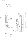
- the cleaned feed air is in a throttle flow 1 with a pressure of 5 to 70 bar and a separation air stream 31 compressed to pressure column pressure and introduced into the main heat exchanger system 2.
- the maximum pressure on the the operational air can be compressed is carried out by the execution of the Main heat exchanger 2 determined.
- gaseous decomposition air 31 cooled to about its dew point and via line 3 fed to the pressure column 4 of the rectification system.
- the throttle air flow 1 is, as far if the Q-T curve allows, also cooled.
- the rectification system includes: another a low-pressure column 5, which at a pressure between 1.1 and 3 bar, preferably between 1.3 and 1.7 bar, is operated.
- the pressure column 4 and the Low pressure column 5 are in thermal contact via the main condenser 6.
- Gaseous nitrogen 7 from the top of the pressure column 4 is in the main condenser 6 in heat exchange with liquid oxygen, the bottom of line 8 Low pressure column 5 is removed, liquefied.
- the evaporating oxygen is introduced back into the low pressure column 5 via line 15.
- the liquid On the one hand, nitrogen is applied to the pressure column 4 as reflux liquid 9, on the other hand, via the preheater 10, a liquid separator 11 fed. A part of the liquid accumulating in the separator 11 is called Return liquid 14 used for the low pressure column 5, the remaining liquid Nitrogen, which is under the top pressure of the low pressure column 5, is via line 12 relaxed in a liquid nitrogen tank 13.
- the liquid nitrogen is in tank 13 preferably under atmospheric pressure. In the preheater 10 Temperature of the nitrogen lowered, so that due to the pressure drop arising when the liquid nitrogen is introduced into the tank 13 Evaporation losses are very low.
- Liquid oxygen 8 is taken from the bottom of the low-pressure column 5 and partly fed to the main capacitor 6, partly in one Preheat exchanger 16 subcooled.
- the supercooled liquid oxygen is converted into one Liquid oxygen tank 17 introduced, in which the oxygen is under atmospheric pressure is stored.
- the liquid nitrogen from the tank 13 is pumped to a pressure of brought up to 200 bar and then passed to the preheater 10 (Line 19).
- the pressure nitrogen the temperature of 80 K, for example, in countercurrent to that from the main capacitor 6 stripped nitrogen heated to about 95 K.
- the pressure nitrogen heated in this way is passed via line 20 to the main heat exchanger 2.
- line 20 branches into that in heat exchanger 2 leading lines 21a and 21b.
- the line 21a is under high pressure standing nitrogen is passed directly into the heat exchanger 2, where it evaporates and can then via line 22a as a high pressure product with a pressure of preferably up to 60 bar.
- the pressure of the in the Main heat exchanger 2 directed nitrogen can also be higher than 60 bar However, maximum pressure is due to the pressure resistance of the heat exchanger 2 certainly. A portion of the pressure nitrogen 20 can then be relaxed in line 21b evaporated and via line 22b as a gaseous product of medium pressure be removed.
- At least part of the oxygen stored in the tank 17 is produced in an analogous manner internally compressed by the two pumps 23a and 23b.
- the two oxygen flows brought to increased pressure through Heat exchange with that obtained from the bottom of the low pressure column 5 Oxygen flow warmed. After the evaporation of the internally compressed oxygen in the main heat exchanger 2 becomes more gaseous via the lines 24a and 24b Deducted oxygen of increased pressure.
- FIG. 2 shows a variant of the air separation plant according to the invention, wherein in Figures 1 and 2, the same parts of the system are designated by the same reference numerals.
- the system according to FIG. 2 differs from the system shown in FIG. 1 essentially in that now with the pumps 18 and 23rd internally compressed product flows in the preheater 30 against the cold Leaving the main heat exchanger 2 emerging throttle air flow 1 are heated.
- the preheater 10 and 16 for heating the internally compressed nitrogen or oxygen against the corresponding ones from the low pressure column 5 withdrawn product flows are eliminated.
- the variant described with reference to FIG. 2 is particularly advantageous if when the compressed throttle air emerging from the main heat exchanger 2 is warmer than the rectification products. This will improve the preheating of the achieved liquid products under increased pressure and the equipment effort becomes lower, since instead of two preheater exchangers, only one preheater exchanger necessary is
Landscapes
- Engineering & Computer Science (AREA)
- Physics & Mathematics (AREA)
- Mechanical Engineering (AREA)
- Thermal Sciences (AREA)
- General Engineering & Computer Science (AREA)
- Health & Medical Sciences (AREA)
- Emergency Medicine (AREA)
- Separation By Low-Temperature Treatments (AREA)
- Manufacture And Refinement Of Metals (AREA)
- Organic Low-Molecular-Weight Compounds And Preparation Thereof (AREA)
Abstract
Description
- Figur 1
- eine erfindungsgemäße Luftzerlegungsanlage zur Gewinnung von Sauerstoff und Stickstoff unter erhöhtem Druck in Kombination mit einer Notversorgung und
- Figur 2
- eine Variante einer derartigen Anlage.
Claims (10)
- Verfahren zur Tieftemperaturluftzerlegung von Luft durch Rektifikation, wobeiverdichtete Einsatzluft in einem Hauptwärmetauscher abgekühlt und einem Rektifiziersystem zugeführt wird,eine flüssige Fraktion in dem Rektifiziersystem gewonnen und in einem Tank gespeichert wird,zumindest ein Teil der flüssigen Fraktion aus dem Tank entnommen und auf einen erhöhten Druck gebracht wird,
und im normalen Betriebdie auf erhöhten Druck gebrachte flüssige Fraktion in einem Vorwärmetauscher erwärmtund in dem Hauptwärmetauscher verdampft wird,wobei Produktgas unter erhöhtem Druck gewonnen wird,
während bei einer Betriebsstörungzumindest ein Teil des Flüssigproduktes aus dem Tank entnommen, verdampft und zur Notversorgung verwendet wird. - Verfahren nach Anspruch 1, dadurch gekennzeichnet, daß die auf erhöhten Druck gebrachte flüssige Fraktion in indirektem Wärmeaustausch mit einer in dem Rektifiziersystem gewonnenen Fraktion erwärmt wird.
- Verfahren nach Anspruch 2, dadurch gekennzeichnet, daß die auf erhöhten Druck gebrachte flüssige Fraktion in indirektem Wärmeaustausch mit der in den Tank geführten Fraktion erwärmt wird.
- Verfahren nach Anspruch 1, dadurch gekennzeichnet, daß die auf erhöhten Druck gebrachte flüssige Fraktion in indirektem Wärmeaustausch mit der aus dem Hauptwärmetauscher austretenden, verdichteten Einsatzluft erwärmt wird.
- Verfahren nach einem der Ansprüche 1 bis 4, dadurch gekennzeichnet, daß Sauerstoff als flüssige Fraktion gewonnen wird.
- Verfahren nach einem der Ansprüche 1 bis 5, dadurch gekennzeichnet, daß Stickstoff als flüssige Fraktion gewonnen wird.
- Verfahren nach einem der Ansprüche 1 bis 6, dadurch gekennzeichnet, daß bei einer Betriebsstörung die flüssige Fraktion in indirektem Wärmeaustausch mit Luft oder Wasser verdampft wird.
- Vorrichtung zur Tieftemperaturzerlegung von Luftmit einem Rektifiziersystem,einer Einsatzluftleitung, die in einen Hauptwärmetauscher und von diesem in das Rektifiziersystem führtmit einer Leitung zur Entnahme einer flüssigen Fraktion aus dem Rektifiziersystem und zu deren Einleitung in einen Tank,einer Flüssigproduktleitung für die flüssige Fraktion von dem Tank zu einem Vorwärmetauscher,einer Verbindung zwischen dem Vorwärmetauscher und dem Hauptwärmetauscher,einer Produktleitung zur Entnahme der verdampften flüssigen Fraktion als gasförmiges Druckprodukt aus dem Hauptwärmetauscher,einer in der Flüssigproduktleitung angeordneten Vorrichtung zur Druckerhöhung der flüssigen Fraktion,und einer stromabwärts der Vorrichtung zur Druckerhöhung der flüssigen Fraktion von der Flüssigproduktleitung abzweigenden Leitung zu einer Verdampfungsvorrichtung zur Notversorgung.
- Vorrichtung nach Anspruch 8, dadurch gekennzeichnet, daß der Vorwärmetauscher in der Leitung zur Entnahme der flüssigen Fraktion aus dem Rektifiziersystem angeordnet ist.
- Vorrichtung nach Anspruch 8, dadurch gekennzeichnet, daß der Vorwärmetauscher in der Einsatzluftleitung stromabwärts des Hauptwärmetauschers angeordnet ist.
Applications Claiming Priority (2)
| Application Number | Priority Date | Filing Date | Title |
|---|---|---|---|
| DE19732887A DE19732887A1 (de) | 1997-07-30 | 1997-07-30 | Verfahren zur Luftzerlegung |
| DE19732887 | 1997-07-30 |
Publications (3)
| Publication Number | Publication Date |
|---|---|
| EP0895045A2 true EP0895045A2 (de) | 1999-02-03 |
| EP0895045A3 EP0895045A3 (de) | 1999-06-16 |
| EP0895045B1 EP0895045B1 (de) | 2002-11-27 |
Family
ID=7837412
Family Applications (1)
| Application Number | Title | Priority Date | Filing Date |
|---|---|---|---|
| EP98113793A Expired - Lifetime EP0895045B1 (de) | 1997-07-30 | 1998-07-23 | Verfahren zur Luftzerlegung |
Country Status (8)
| Country | Link |
|---|---|
| US (1) | US6038885A (de) |
| EP (1) | EP0895045B1 (de) |
| BR (1) | BR9802805A (de) |
| DE (2) | DE19732887A1 (de) |
| DK (1) | DK0895045T3 (de) |
| ES (1) | ES2187861T3 (de) |
| HU (1) | HU220018B (de) |
| PL (1) | PL186823B1 (de) |
Families Citing this family (28)
| Publication number | Priority date | Publication date | Assignee | Title |
|---|---|---|---|---|
| US6295840B1 (en) | 2000-11-15 | 2001-10-02 | Air Products And Chemicals, Inc. | Pressurized liquid cryogen process |
| GB0219415D0 (en) * | 2002-08-20 | 2002-09-25 | Air Prod & Chem | Process and apparatus for cryogenic separation process |
| FR2849172A1 (fr) * | 2002-12-19 | 2004-06-25 | Air Liquide | Procede de distillation d'air ameliore, et installation de mise en oeuvre de ce procede |
| FR2853407B1 (fr) * | 2003-04-02 | 2012-12-14 | Air Liquide | Procede et installation de fourniture de gaz sous pression |
| FR2855598B1 (fr) * | 2003-05-28 | 2005-10-07 | Air Liquide | Procede et installation de fourniture de secours d'un gaz sous pression par vaporisation de liquide cryogenique |
| FR2872262B1 (fr) * | 2004-06-29 | 2010-11-26 | Air Liquide | Procede et installation de fourniture de secours d'un gaz sous pression |
| DE102005029274A1 (de) * | 2004-08-17 | 2006-02-23 | Linde Ag | Verfahren und Vorrichtung zur Gewinnung eines gasförmigen Druckprodukts durch Tieftemperatur-Zerlegung von Luft |
| DE102007031765A1 (de) | 2007-07-07 | 2009-01-08 | Linde Ag | Verfahren zur Tieftemperaturzerlegung von Luft |
| DE102007031759A1 (de) | 2007-07-07 | 2009-01-08 | Linde Ag | Verfahren und Vorrichtung zur Erzeugung von gasförmigem Druckprodukt durch Tieftemperaturzerlegung von Luft |
| DE102009034979A1 (de) | 2009-04-28 | 2010-11-04 | Linde Aktiengesellschaft | Verfahren und Vorrichtung zur Erzeugung von gasförmigem Drucksauerstoff |
| EP2312248A1 (de) | 2009-10-07 | 2011-04-20 | Linde Aktiengesellschaft | Verfahren und Vorrichtung Gewinnung von Drucksauerstoff und Krypton/Xenon |
| DE102010052545A1 (de) | 2010-11-25 | 2012-05-31 | Linde Aktiengesellschaft | Verfahren und Vorrichtung zur Gewinnung eines gasförmigen Druckprodukts durch Tieftemperaturzerlegung von Luft |
| DE102010052544A1 (de) | 2010-11-25 | 2012-05-31 | Linde Ag | Verfahren zur Gewinnung eines gasförmigen Druckprodukts durch Tieftemperaturzerlegung von Luft |
| DE102011015233A1 (de) * | 2011-03-25 | 2012-09-27 | Linde Ag | Vorrichtung zur Tieftemperaturzerlegung von Luft |
| EP2520886A1 (de) | 2011-05-05 | 2012-11-07 | Linde AG | Verfahren und Vorrichtung zur Erzeugung eines gasförmigen Sauerstoff-Druckprodukts durch Tieftemperaturzerlegung von Luft |
| DE102011112909A1 (de) | 2011-09-08 | 2013-03-14 | Linde Aktiengesellschaft | Verfahren und Vorrichtung zur Gewinnung von Stahl |
| EP2600090B1 (de) | 2011-12-01 | 2014-07-16 | Linde Aktiengesellschaft | Verfahren und Vorrichtung zur Erzeugung von Drucksauerstoff durch Tieftemperaturzerlegung von Luft |
| DE102011121314A1 (de) | 2011-12-16 | 2013-06-20 | Linde Aktiengesellschaft | Verfahren zur Erzeugung eines gasförmigen Sauerstoff-Druckprodukts durch Tieftemperaturzerlegung von Luft |
| DE102012017488A1 (de) | 2012-09-04 | 2014-03-06 | Linde Aktiengesellschaft | Verfahren zur Erstellung einer Luftzerlegungsanlage, Luftzerlegungsanlage und zugehöriges Betriebsverfahren |
| EP2784420A1 (de) | 2013-03-26 | 2014-10-01 | Linde Aktiengesellschaft | Verfahren zur Luftzerlegung und Luftzerlegungsanlage |
| WO2014154339A2 (de) | 2013-03-26 | 2014-10-02 | Linde Aktiengesellschaft | Verfahren zur luftzerlegung und luftzerlegungsanlage |
| EP2801777A1 (de) | 2013-05-08 | 2014-11-12 | Linde Aktiengesellschaft | Luftzerlegungsanlage mit Hauptverdichterantrieb |
| DE102013017590A1 (de) | 2013-10-22 | 2014-01-02 | Linde Aktiengesellschaft | Verfahren zur Gewinnung eines Krypton und Xenon enthaltenden Fluids und hierfür eingerichtete Luftzerlegungsanlage |
| TR201808162T4 (tr) | 2014-07-05 | 2018-07-23 | Linde Ag | Havanın düşük sıcaklıkta ayrıştırılması vasıtasıyla bir basınçlı gaz ürününün kazanılmasına yönelik yöntem ve cihaz. |
| PL2963370T3 (pl) | 2014-07-05 | 2018-11-30 | Linde Aktiengesellschaft | Sposób i urządzenie do kriogenicznego rozdziału powietrza |
| EP2963369B1 (de) | 2014-07-05 | 2018-05-02 | Linde Aktiengesellschaft | Verfahren und vorrichtung zur tieftemperaturzerlegung von luft |
| EP2963367A1 (de) | 2014-07-05 | 2016-01-06 | Linde Aktiengesellschaft | Verfahren und Vorrichtung zur Tieftemperaturzerlegung von Luft mit variablem Energieverbrauch |
| DE102015100714B4 (de) | 2015-01-19 | 2023-03-02 | Anton Paar Gmbh | Scherrheometer |
Citations (5)
| Publication number | Priority date | Publication date | Assignee | Title |
|---|---|---|---|---|
| US5408831A (en) * | 1992-12-30 | 1995-04-25 | L'air Liquide, Societe Anonyme Pour L'etude Et L'exploitation Des Procedes Georges Claude | Process and installation for the production of gaseous oxygen under pressure |
| EP0681153A1 (de) * | 1994-05-04 | 1995-11-08 | Linde Aktiengesellschaft | Verfahren und Vorrichtung zur Tieftemperaturzerlegung von Luft |
| US5526647A (en) * | 1994-07-29 | 1996-06-18 | L'air Liquide, Societe Anonyme Pour L'etude Et L'exploitation Des Procedes Georges Claude | Process and installation for the production of gaseous oxygen under pressure at a variable flow rate |
| US5566556A (en) * | 1993-06-07 | 1996-10-22 | L'air Liquide, Societe Anonyme Pour L'etude Et L'exploitation Des Procedes Georges Claude | Process and unit for supplying a gas under pressure to an installation that consumes a constituent of air |
| EP0848220A1 (de) * | 1996-12-12 | 1998-06-17 | L'air Liquide, Societe Anonyme Pour L'etude Et L'exploitation Des Procedes Georges Claude | Verfahren und Anlage zur Lieferung eines Luftgases in variablen Mengen |
Family Cites Families (6)
| Publication number | Priority date | Publication date | Assignee | Title |
|---|---|---|---|---|
| FR1166565A (fr) * | 1956-01-04 | 1958-11-13 | Union Carbide & Carbon Corp | Procédé et installation de séparation par rectification de mélanges gazeux |
| GB929798A (en) * | 1960-04-11 | 1963-06-26 | British Oxygen Co Ltd | Low temperature separation of air |
| FR2670278B1 (fr) * | 1990-12-06 | 1993-01-22 | Air Liquide | Procede et installation de distillation d'air en regime variable de production d'oxygene gazeux. |
| JP2909678B2 (ja) * | 1991-03-11 | 1999-06-23 | レール・リキード・ソシエテ・アノニム・プール・レテュード・エ・レクスプロワタシオン・デ・プロセデ・ジョルジュ・クロード | 圧力下のガス状酸素の製造方法及び製造装置 |
| CN1071444C (zh) * | 1992-02-21 | 2001-09-19 | 普拉塞尔技术有限公司 | 生产气体氧的低温空气分离系统 |
| GB9521996D0 (en) * | 1995-10-27 | 1996-01-03 | Boc Group Plc | Air separation |
-
1997
- 1997-07-30 DE DE19732887A patent/DE19732887A1/de not_active Withdrawn
-
1998
- 1998-07-09 PL PL98327374A patent/PL186823B1/pl not_active IP Right Cessation
- 1998-07-17 HU HU9801620A patent/HU220018B/hu not_active IP Right Cessation
- 1998-07-23 DK DK98113793T patent/DK0895045T3/da active
- 1998-07-23 ES ES98113793T patent/ES2187861T3/es not_active Expired - Lifetime
- 1998-07-23 EP EP98113793A patent/EP0895045B1/de not_active Expired - Lifetime
- 1998-07-23 DE DE59806410T patent/DE59806410D1/de not_active Expired - Fee Related
- 1998-07-30 US US09/126,150 patent/US6038885A/en not_active Expired - Fee Related
- 1998-07-30 BR BR9802805-7A patent/BR9802805A/pt not_active IP Right Cessation
Patent Citations (5)
| Publication number | Priority date | Publication date | Assignee | Title |
|---|---|---|---|---|
| US5408831A (en) * | 1992-12-30 | 1995-04-25 | L'air Liquide, Societe Anonyme Pour L'etude Et L'exploitation Des Procedes Georges Claude | Process and installation for the production of gaseous oxygen under pressure |
| US5566556A (en) * | 1993-06-07 | 1996-10-22 | L'air Liquide, Societe Anonyme Pour L'etude Et L'exploitation Des Procedes Georges Claude | Process and unit for supplying a gas under pressure to an installation that consumes a constituent of air |
| EP0681153A1 (de) * | 1994-05-04 | 1995-11-08 | Linde Aktiengesellschaft | Verfahren und Vorrichtung zur Tieftemperaturzerlegung von Luft |
| US5526647A (en) * | 1994-07-29 | 1996-06-18 | L'air Liquide, Societe Anonyme Pour L'etude Et L'exploitation Des Procedes Georges Claude | Process and installation for the production of gaseous oxygen under pressure at a variable flow rate |
| EP0848220A1 (de) * | 1996-12-12 | 1998-06-17 | L'air Liquide, Societe Anonyme Pour L'etude Et L'exploitation Des Procedes Georges Claude | Verfahren und Anlage zur Lieferung eines Luftgases in variablen Mengen |
Also Published As
| Publication number | Publication date |
|---|---|
| PL186823B1 (pl) | 2004-03-31 |
| ES2187861T3 (es) | 2003-06-16 |
| PL327374A1 (en) | 1999-02-01 |
| EP0895045B1 (de) | 2002-11-27 |
| US6038885A (en) | 2000-03-21 |
| DE59806410D1 (de) | 2003-01-09 |
| EP0895045A3 (de) | 1999-06-16 |
| HU220018B (hu) | 2001-10-28 |
| DK0895045T3 (da) | 2003-03-03 |
| DE19732887A1 (de) | 1999-02-04 |
| HU9801620D0 (en) | 1998-09-28 |
| BR9802805A (pt) | 1999-10-05 |
| HUP9801620A1 (hu) | 1999-03-29 |
Similar Documents
| Publication | Publication Date | Title |
|---|---|---|
| EP0895045B1 (de) | Verfahren zur Luftzerlegung | |
| EP1067345B1 (de) | Verfahren und Vorrichtung zur Tieftemperaturzerlegung von Luft | |
| DE19815885A1 (de) | Verfahren und Vorrichtung zur Erzeugung von gasförmigem Druckprodukt bei der Tieftemperaturzerlegung von Luft | |
| DE102007014643A1 (de) | Verfahren und Vorrichtung zur Erzeugung von gasförmigem Druckprodukt durch Tieftemperaturzerlegung von Luft | |
| EP0669509A1 (de) | Verfahren und Vorrichtung zur Gewinnung von reinem Argon | |
| WO1997004279A1 (de) | Verfahren und vorrichtung zur variablen erzeugung eines gasförmigen druckprodukts | |
| DE102005029274A1 (de) | Verfahren und Vorrichtung zur Gewinnung eines gasförmigen Druckprodukts durch Tieftemperatur-Zerlegung von Luft | |
| DE19954593A1 (de) | Verfahren und Vorrichtung zur Tieftemperaturzerlegung von Luft | |
| DE10332863A1 (de) | Verfahren und Vorrichtung zur Gewinnung von Krypton und/oder Xenon durch Tieftemperaturzerlegung von Luft | |
| DE102010056560A1 (de) | Verfahren und Vorrichtung zur Gewinnung von Drucksauerstoff und Druckstickstoff durch Tieftemperaturzerlegung von Luft | |
| DE10213212A1 (de) | Verfahren und Vorrichtung zur Erzeugung zweier Druckprodukte durch Tieftemperatur-Luftzerlegung | |
| DE10103968A1 (de) | Drei-Säulen-System zur Tieftemperaturzerlegung von Luft | |
| EP2053331A1 (de) | Verfahren und Vorrichtung zur Tieftemperatur-Luftzerlegung | |
| EP4065910A1 (de) | Verfahren und anlage zur tieftemperaturzerlegung von luft | |
| DE10232430A1 (de) | Verfahren und Vorrichtung zur Gewinnung von Krypton und/oder Xenon durch Tieftemperaturzerlegung von Luft | |
| DE10205096A1 (de) | Verfahren und Vorrichtung zur Gewinnung hoch reinen Sauerstoffs aus weniger reinem Sauerstoff | |
| EP1001236B1 (de) | Verfahren zur Gewinnung von ultrareinem Stickstoff | |
| DE10045128A1 (de) | Verfahren und Vorrichtung zur Erzeugung hoch reinen Stickstoffs durch Tieftemperatur-Luftzerlegung | |
| DE20319823U1 (de) | Vorrichtung zur Gewinnung von Krypton und/oder Xenon durch Tieftemperaturzerlegung | |
| DE2518557C3 (de) | Verfahren zur Luftzerlegung mit Flüssigkeitserzeugung durch Tieftemperaturrektifikation | |
| DE202018006161U1 (de) | Anlage zur Tieftemperaturzerlegung von Luft | |
| EP1189002A1 (de) | Verfahren und Vorrichtung zur Gewinnung eines gasförmigen Produkts durch Tieftemperaturzerlegung von Luft | |
| DE102021117030B4 (de) | Gasgemisch-Zerlegungsanlage sowie Verfahren zum Abtrennen von wenigstens einem Hauptfluid aus einem Gasgemisch | |
| EP1837614A1 (de) | Verfahren und Vorrichtung zum Verdampfen einer sauerstoffangereicherten Einsatzflüssigkeit und Verfahren und Vorrichtung zur Tieftemperaturzerlegung von Luft | |
| WO2020083525A1 (de) | Verfahren und anlage zur tieftemperaturzerlegung von luft |
Legal Events
| Date | Code | Title | Description |
|---|---|---|---|
| PUAI | Public reference made under article 153(3) epc to a published international application that has entered the european phase |
Free format text: ORIGINAL CODE: 0009012 |
|
| AK | Designated contracting states |
Kind code of ref document: A2 Designated state(s): DE DK ES FI FR GB IT SE |
|
| AX | Request for extension of the european patent |
Free format text: AL;LT;LV;MK;RO;SI |
|
| PUAL | Search report despatched |
Free format text: ORIGINAL CODE: 0009013 |
|
| AK | Designated contracting states |
Kind code of ref document: A3 Designated state(s): AT BE CH CY DE DK ES FI FR GB GR IE IT LI LU MC NL PT SE |
|
| AX | Request for extension of the european patent |
Free format text: AL;LT;LV;MK;RO;SI |
|
| 17P | Request for examination filed |
Effective date: 19990617 |
|
| AKX | Designation fees paid |
Free format text: DE DK ES FI FR GB IT SE |
|
| 17Q | First examination report despatched |
Effective date: 20010921 |
|
| GRAG | Despatch of communication of intention to grant |
Free format text: ORIGINAL CODE: EPIDOS AGRA |
|
| GRAG | Despatch of communication of intention to grant |
Free format text: ORIGINAL CODE: EPIDOS AGRA |
|
| GRAH | Despatch of communication of intention to grant a patent |
Free format text: ORIGINAL CODE: EPIDOS IGRA |
|
| GRAH | Despatch of communication of intention to grant a patent |
Free format text: ORIGINAL CODE: EPIDOS IGRA |
|
| GRAA | (expected) grant |
Free format text: ORIGINAL CODE: 0009210 |
|
| AK | Designated contracting states |
Kind code of ref document: B1 Designated state(s): DE DK ES FI FR GB IT SE |
|
| REG | Reference to a national code |
Ref country code: GB Ref legal event code: FG4D Free format text: NOT ENGLISH |
|
| REF | Corresponds to: |
Ref document number: 59806410 Country of ref document: DE Date of ref document: 20030109 |
|
| REG | Reference to a national code |
Ref country code: DK Ref legal event code: T3 |
|
| GBT | Gb: translation of ep patent filed (gb section 77(6)(a)/1977) |
Effective date: 20030326 |
|
| REG | Reference to a national code |
Ref country code: ES Ref legal event code: FG2A Ref document number: 2187861 Country of ref document: ES Kind code of ref document: T3 |
|
| ET | Fr: translation filed | ||
| PLBE | No opposition filed within time limit |
Free format text: ORIGINAL CODE: 0009261 |
|
| STAA | Information on the status of an ep patent application or granted ep patent |
Free format text: STATUS: NO OPPOSITION FILED WITHIN TIME LIMIT |
|
| 26N | No opposition filed |
Effective date: 20030828 |
|
| REG | Reference to a national code |
Ref country code: FR Ref legal event code: CA |
|
| PGFP | Annual fee paid to national office [announced via postgrant information from national office to epo] |
Ref country code: ES Payment date: 20080821 Year of fee payment: 11 Ref country code: DK Payment date: 20080721 Year of fee payment: 11 Ref country code: DE Payment date: 20080807 Year of fee payment: 11 |
|
| PGFP | Annual fee paid to national office [announced via postgrant information from national office to epo] |
Ref country code: IT Payment date: 20080729 Year of fee payment: 11 Ref country code: FR Payment date: 20080718 Year of fee payment: 11 Ref country code: FI Payment date: 20080714 Year of fee payment: 11 |
|
| PGFP | Annual fee paid to national office [announced via postgrant information from national office to epo] |
Ref country code: GB Payment date: 20080723 Year of fee payment: 11 |
|
| PGFP | Annual fee paid to national office [announced via postgrant information from national office to epo] |
Ref country code: SE Payment date: 20080709 Year of fee payment: 11 |
|
| REG | Reference to a national code |
Ref country code: DK Ref legal event code: EBP |
|
| EUG | Se: european patent has lapsed | ||
| GBPC | Gb: european patent ceased through non-payment of renewal fee |
Effective date: 20090723 |
|
| REG | Reference to a national code |
Ref country code: FR Ref legal event code: ST Effective date: 20100331 |
|
| PG25 | Lapsed in a contracting state [announced via postgrant information from national office to epo] |
Ref country code: FR Free format text: LAPSE BECAUSE OF NON-PAYMENT OF DUE FEES Effective date: 20090731 Ref country code: FI Free format text: LAPSE BECAUSE OF NON-PAYMENT OF DUE FEES Effective date: 20090723 |
|
| PG25 | Lapsed in a contracting state [announced via postgrant information from national office to epo] |
Ref country code: GB Free format text: LAPSE BECAUSE OF NON-PAYMENT OF DUE FEES Effective date: 20090723 |
|
| PG25 | Lapsed in a contracting state [announced via postgrant information from national office to epo] |
Ref country code: DE Free format text: LAPSE BECAUSE OF NON-PAYMENT OF DUE FEES Effective date: 20100202 |
|
| PG25 | Lapsed in a contracting state [announced via postgrant information from national office to epo] |
Ref country code: DK Free format text: LAPSE BECAUSE OF NON-PAYMENT OF DUE FEES Effective date: 20090731 |
|
| REG | Reference to a national code |
Ref country code: ES Ref legal event code: FD2A Effective date: 20090724 |
|
| PG25 | Lapsed in a contracting state [announced via postgrant information from national office to epo] |
Ref country code: ES Free format text: LAPSE BECAUSE OF NON-PAYMENT OF DUE FEES Effective date: 20090724 |
|
| PG25 | Lapsed in a contracting state [announced via postgrant information from national office to epo] |
Ref country code: IT Free format text: LAPSE BECAUSE OF NON-PAYMENT OF DUE FEES Effective date: 20090723 |
|
| PG25 | Lapsed in a contracting state [announced via postgrant information from national office to epo] |
Ref country code: SE Free format text: LAPSE BECAUSE OF NON-PAYMENT OF DUE FEES Effective date: 20090724 |