EP0893888A2 - Appareil de communication à spectre étalé et récepteur du type RAKE - Google Patents
Appareil de communication à spectre étalé et récepteur du type RAKE Download PDFInfo
- Publication number
- EP0893888A2 EP0893888A2 EP98113903A EP98113903A EP0893888A2 EP 0893888 A2 EP0893888 A2 EP 0893888A2 EP 98113903 A EP98113903 A EP 98113903A EP 98113903 A EP98113903 A EP 98113903A EP 0893888 A2 EP0893888 A2 EP 0893888A2
- Authority
- EP
- European Patent Office
- Prior art keywords
- powers
- interference
- weighting
- paths
- path
- Prior art date
- Legal status (The legal status is an assumption and is not a legal conclusion. Google has not performed a legal analysis and makes no representation as to the accuracy of the status listed.)
- Withdrawn
Links
Images


Classifications
-
- H—ELECTRICITY
- H04—ELECTRIC COMMUNICATION TECHNIQUE
- H04L—TRANSMISSION OF DIGITAL INFORMATION, e.g. TELEGRAPHIC COMMUNICATION
- H04L27/00—Modulated-carrier systems
- H04L27/26—Systems using multi-frequency codes
- H04L27/30—Systems using multi-frequency codes wherein each code element is represented by a combination of frequencies
-
- H—ELECTRICITY
- H04—ELECTRIC COMMUNICATION TECHNIQUE
- H04B—TRANSMISSION
- H04B1/00—Details of transmission systems, not covered by a single one of groups H04B3/00 - H04B13/00; Details of transmission systems not characterised by the medium used for transmission
- H04B1/69—Spread spectrum techniques
- H04B1/707—Spread spectrum techniques using direct sequence modulation
- H04B1/7097—Interference-related aspects
- H04B1/711—Interference-related aspects the interference being multi-path interference
- H04B1/7115—Constructive combining of multi-path signals, i.e. RAKE receivers
- H04B1/712—Weighting of fingers for combining, e.g. amplitude control or phase rotation using an inner loop
Definitions
- the present invention relates to a communication apparatus used in a digital mobile communication system such as a car/portable telephone system, a cordless telephone system, or a radio LAN system and, more particularly, to a spread spectrum communication apparatus for performing radio communication by using a code division multiple access (CDMA) scheme or a multicode transmission scheme.
- a digital mobile communication system such as a car/portable telephone system, a cordless telephone system, or a radio LAN system
- CDMA code division multiple access
- a spread spectrum communication system performs communication as follows. First of all, the transmitting communication apparatus modulates digital speech data or digital image data by digital modulation such as PSK modulation. The modulated data is converted into a broadband baseband signal by using spreading codes. The spread transmission signal is converted into an RF signal and is then transmitted. The receiving communication apparatus despreads the received RF signal by using the same spreading codes as those used in the transmitting communication apparatus. Digital demodulation is then performed for the despread reception signal by digital demodulation such as PSK demodulation, thereby reconstructing original data from reception data.
- digital modulation such as PSK modulation
- a RAKE receiver is used as one of measures against multipath interference.
- the radio wave transmitted from the transmitting apparatus may directly arrive at the receiving apparatus, or may arrive at the receiving apparatus upon being reflected by a building, a mountain, and the like. If one radio wave reaches the receiving apparatus through a plurality of paths with different delay times, waveform distortion occurs. This phenomenon is called multipath effects.
- multipath radio signals received by one antenna with different delay times can be separated in units of spreading code length (chip interval).
- the received multipath signals are respectively input to a plurality of independent demodulators. These demodulators despread the signals with spreading codes of time phases corresponding to the respective paths.
- the despread reception signals from the respective paths are synthesized into symbols, reconstructing original data from reception data.
- This reception scheme is called RAKE reception because the receiver has a RAKE-like arrangement. With the use of a RAKE receive, path diversity is obtained. This can greatly improve the reception quality of the signal transmitted through a multipath transmission channel.
- a RAKE receiver In a RAKE receiver, after delay units give different delay amounts to the multipath signals received by a radio circuit for the respective paths, multipliers multiply the resultant signals by the spreading codes generated by a spreading code generator, thereby separating the reception signals for the respective paths. These reception signals are integrated by integral damping filters for a 1-symbol interval. Synchronization and weighting are performed for the integral outputs, and the resultant output signals are synthesized. The above weighting is performed by determining weights in proportion to the amplitudes of the reception signals detected from the respective paths, and multiplying the integral outputs by the determined weights. In this RAKE receiver, therefore, the reception signals from a plurality of paths are subjected to maximum ratio synthesis. As a result, a maximum diversity gain can be obtained.
- the reception signal output from the RAKE receiver does not have an optimal desired-to-undesired signal ratio (D/U) even if maximum ratio synthesis is performed.
- the above problems may arise even in a spread spectrum communication system for performing so-called multicode transmission, i.e., transmitting data from one radio station to another radio station by using a bundle of channels using different spreading codes.
- the present invention has been made in consideration of the above situation, and has as its object to provide a RAKE receiver that can always obtain a high desired-to-undesired signal ratio even if the spread spectrum signal transmitted from one radio station is received through a multipath transmission channel, and a spread spectrum communication apparatus including the RAKE receiver.
- a RAKE receiver and a spread spectrum communication apparatus each include a weighting coefficient generating means as a constituent element for RAKE reception.
- the weighting coefficient generating means obtains a reception signal power for each path of a multipath transmission channel and interference powers from the remaining paths, and generates weighting coefficients for equalizing the interference powers contained in the reception signals from the respective paths on the basis of the reception signal powers and the interference powers.
- the reception signals from the respective paths are weighted on the basis of the generated weighting coefficients.
- the weighted reception signals from the respective paths are synthesized.
- a weighting coefficient for each of a plurality of paths is obtained in consideration of not only the signal power on the path of interest but also the interference powers from the remaining paths.
- the reception signals from the respective paths are then weighted on the basis of the obtained weighting coefficients.
- optimal weighting processing can be performed for the reception signals from the respective paths to equalize the interference powers contained in the reception signals from the respective paths even if the interference powers applied from other paths to each path cannot be regarded as equipower white Gaussian noise as in a case in which a spread spectrum signal is transmitted from a base station to a mobile station in a CDMA mobile communication system through a multipath transmission channel.
- An optimal desired-to-undesired signal ratio can therefore be obtained as compared with the conventional system in which the reception signals from the respective paths are synthesized by maximum ratio synthesis.
- the present invention is characterized in that the weighting coefficient generating means obtains a reception signal power for each path of a multipath transmission channel, a power corresponding to thermal noise contained in the reception signal from the path, and an interference power from another path, and generates weighting coefficients for equalizing the thermal noise and interference powers contained in the reception signals from the respective paths on the basis of the reception signal powers, the thermal noise powers, and the interference powers.
- a weighting coefficient for each path is calculated in consideration of thermal noise powers in addition to the signal power on the path and the interference powers from the remaining paths. Even if, therefore, the reception signals from the respective paths contain different thermal noise powers, the interference powers containing the thermal noise can be equalized among the paths. With this operation, when maximum ratio synthesis is performed, a reception signal with a higher desired-to-undesired signal ratio can be obtained.
- the present invention is further characterized in that the weighting coefficient generating means obtains a reception signal power for each path of a multipath transmission channel, a first interference power from another path, and a second interference power from a second communication apparatus other than the first communication apparatus, and generates weighting coefficients for equalizing the interference powers contained in the reception signals from the respective paths on the basis of the reception signal powers and the first and second interference powers.
- a weighting coefficient for each path is calculated in consideration of, for example, intercell interference powers or interference powers from other radio stations in addition to the signal power on the path and the interference powers from the remaining paths.
- optimal weighting for each path can be performed in accordance with the actual situation, thereby obtaining a reception signal with a higher desired-to-undesired signal ratio.
- the present invention is characterized by comprising one arithmetic circuit, and time-divisionally calculating weighting coefficients for all paths by using the arithmetic circuit.
- a plurality of arithmetic circuits need not be used. This simplifies and miniaturizes the circuit arrangement.
- the present invention is also characterized by comprising arithmetic circuits corresponding to the number of paths, and concurrently calculating weighting coefficients for the respective paths by using the arithmetic circuits.
- FIG. 1 is a block diagram showing a mobile communication apparatus including a RAKE receiver according to the first embodiment of the present invention.
- a transmission speech signal of a speaker output from a microphone 10a is converted into a digital signal by an analog-to-digital converter (A-D) 11a.
- the digital signal is then coded by a voice coder-decoder (to be referred to as a vocoder hereinafter) 12.
- a microprocessor (MPU) 13 adds a control signal and the like to the coded transmission signal output from the vocoder 12 to generate transmission data.
- a data conditioner 14 adds an error detection code and an error correction code to this transmission data.
- a convolution coder 15 then codes the data.
- An interleave circuit 16 performs interleave processing for the data.
- the transmission data output from the interleave circuit 16 is spread to a broadband signal with spreading codes by a spread spectrum unit 17.
- the spreading codes for example, a PN code (pseudo noise code) and an orthogonal code using a Walsh sequence, an Orthogonal Gold sequence, or the like are used together.
- the orthogonal code is used to improve the orthogonality between channels so as to further suppress interference.
- a digital filter 18 removes unwanted frequency components from this spread spectrum transmission signal.
- the resultant signal is converted into an analog signal by a digital-to-analog converter (D-A) 19.
- D-A digital-to-analog converter
- This analog transmission signal is up-converted into a predetermined radio frequency and power-amplified to a predetermined transmission power level by an analog front end 20. Thereafter, the transmission signal is transmitted from an antenna 21 to, for example, a base station.
- the spread spectrum radio signal received by the antenna 21 is amplified by a low-noise amplifier in the analog front end 20 and is also down-converted into an intermediate or baseband frequency.
- the reception signal output from the analog front end 20 is converted into a digital signal at a predetermined sampling period by an analog-to-digital converter (A-D) 22.
- A-D analog-to-digital converter
- the digital signal is then input to a search receiver 23, an automatic gain control (AGC) circuit 24, and a RAKE receiver 25.
- AGC automatic gain control
- the RAKE receiver 25 includes three finger circuits for separating the signals received through three different paths from a multipath radio signal and reconstructing original signals from the respective reception signals, and a symbol synthesizer for synthesizing symbols from the output signals from these finger circuits.
- the search receiver 23 searches for the PN code of the pilot signal broadcast from a base station, and acquires the offset of the code.
- the search receiver 23 basically has the same arrangement as that of the finger circuit.
- the power control data obtained by this PN code search is loaded into the microprocessor 13.
- the demodulated symbol output from the RAKE receiver 25 is input to a deinterleave circuit 26, together with timing information.
- the deinterleave circuit 26 performs deinterleave processing.
- the demodulated symbol having undergone this deinterleave processing is Viterbi-decoded by a Viterbi decoder 27.
- the demodulated symbol having undergone this Viterbi decoding is subjected to error correction decoding in an error correction circuit 28 to become received data.
- This data is input to the microprocessor 13.
- the microprocessor 13 separates the input received data into speech data and control data.
- the speech data is voice-decoded by the vocoder 12 and is converted into an analog signal by a digital-to-analog converter (D-A) 11b.
- D-A digital-to-analog converter
- a keypad/display 29 is used by the user to input dial data, control data, and the like or to display various pieces of information associated with the operation state of the mobile station.
- the operation of the keypad/display 29 is controlled by the microprocessor 13.
- the RAKE receiver 25 has the following arrangement.
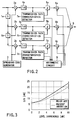
- FIG. 2 is a circuit block diagram showing the arrangement of the RAKE receiver 25, and more specifically, the arrangement for a case in which the radio signals transmitted through three paths are to be synthesized.
- the multipath reception signals that have been received through the antenna (not shown) and have undergone down-conversion of the frequencies in the radio unit are respectively input to multipliers 2a, 2b, and 2c for spread spectrum after different delay amounts are given to the signals by delay units 1a and 1b.
- These multipliers 2a, 2b, and 2c respectively multiply the above multipath reception signals by the spreading codes generated by a spreading code generator 3. With this operation, the reception signals from the respective paths are separated.
- These reception signals are respectively integrated by integral damping filters 4a, 4b, and 4c for a 1-symbol interval.
- the resultant integral outputs are respectively input to weighting multipliers 6a, 6b, and 6c through phase shifters 5a, 5b, and 5c.
- the above integral outputs are also input to transmission channel characteristics detectors 7a, 7b, and 7c, respectively.
- the transmission channel characteristics detectors 7a, 7b, and 7c detect pieces of amplitude information and phase difference information as the transmission channel characteristics of the respective paths.
- the pieces of phase difference information are supplied to the phase shifters 5a, 5b, and 5c.
- the phase shifters 5a, 5b, and 5c perform phase adjustment to match the phases of the respective integral outputs with each other in accordance with the pieces of phase difference information.
- the pieces of amplitude information of paths P1, P2, and P3 which are detected by the transmission channel characteristics detectors 7a, 7b, and 7c are input to an arithmetic circuit 9.
- the arithmetic circuit 9 calculates weighting coefficients for the respective paths P1, P2, and P3 on the basis of the pieces of amplitude information of the paths P1, P2, and P3, detected by the transmission channel characteristics detectors 7a, 7b, and 7c, and supplies the calculated weighting coefficients to the weighting multipliers 6a, 6b, and 6c.
- Each weighting coefficient is calculated by using not only the amplitude information of a corresponding one of the paths P1, P2, and P3 but also the pieces of amplitude information of the two remaining paths.
- weighting coefficients W1, W2, and W3 for the paths P1, P2, and P3 are given by
- path diversity synthesis becomes maximum ratio synthesis because the transmission channel characteristics of the respective paths P1, P2, and P3 are proportional to the weighting coefficients. This function is equivalent to division of the reception power of each path of interest by the total reception power. However, the ratios between the weighting coefficients for the respective paths P1, P2, and P3 are equal to the ratios between the reception powers of the paths P1, P2, and P3.
- the arithmetic circuit 9 obtains the signal power for each path on the basis of the amplitude of the signal from the path of interest, and also obtains the interference power for each path on the basis of the amplitudes of the signals from the remaining paths. The arithmetic circuit 9 then obtains a weighting coefficient for each path of interest in accordance with these calculation results.
- n be the number of paths
- r1, r2,..., ri,..., rn be the amplitudes of the transmission channel characteristics of the respective paths
- weighting coefficients w1, w2,..., wi,..., wn are given by where A is the proportional constant, m is the number of mobile stations or multicodes, and PG is the spread factor.
- the transmission channel characteristics detectors 7a, 7b, and 7c respectively detect pieces of phase difference information and amplitude information of the reception signals from the paths P1, P2, and P3.
- the phase shifters 5a, 5b, and 5c then perform phase adjustment in accordance with the pieces of phase difference information.
- the pieces of amplitude information detected by the transmission channel characteristics detectors 7a, 7b, and 7c are input to the arithmetic circuit 9.
- the arithmetic circuit 9 calculates the weighting coefficients w1, w2, and w3 for the respective paths P1, P2, and P3 according to equation (1).
- the signal power of the signal from the path P1 is obtained from the amplitude r1 of the reception signal from the path P1
- the interference power is then obtained from the amplitudes r2 and r3 of the reception signals from the two remaining paths P2 and P3.
- the optimal weighting coefficient w1 for the path P1 is calculated on the basis of these calculated signal power and interference power.
- the signal power is obtained from the amplitude of the reception signal from the corresponding path, and the interference power for each path is obtained from the amplitudes of the reception signals form the two remaining paths in the same manner as described above.
- the weighting coefficients w2 and w3 are then calculated on the basis of these signal powers and interference powers.
- the weighting coefficients w1, w2, and w3 obtained in this manner are respectively supplied from the arithmetic circuit 9 to the weighting multipliers 6a, 6b, and 6c.
- the weighting multipliers 6a, 6b, and 6c weight the integral outputs from the phase shifters 5a, 5b, and 5c with the above weighting coefficients w1, w2, and w3.
- the weighted reception signals from the respective paths are synthesized into symbols by a symbol synthesizer 8. The resultant signal is used to decode the reception data.
- the first embodiment includes the arithmetic circuit 9 for weighting coefficients.
- This arithmetic circuit 9 obtains the signal power for each path from the amplitude of the reception signal from the corresponding path, and also obtains the interference power from the amplitudes of the reception signals from the two remaining paths.
- the arithmetic circuit 9 then calculates the weighting coefficients w1, w2, and w3 on the basis of the signal powers and the interference powers.
- FIG. 3 shows the relationship between the level ratio between two paths and the desired-to-undesired signal ratio (D/U) in a case in which signals are received by using the RAKE receiver in the present invention in comparison with a conventional maximum ratio synthesis method.
- the scheme of the present invention can obtain better D/U characteristics than the conventional maximum ratio synthesis method.
- the above effects can be obtained in a spread spectrum communication system having a plurality of radio stations distributed, in which an arbitrary radio station performs multicode transmission of data to another radio station through a multipath transmission channel.
- weighting is performed in consideration of the signal power on each path and the interference powers from the remaining paths.
- the "intercell interference + thermal noise" power must also be taken into consideration.
- the "intercell interference + thermal noise" power N can be approximately estimated by obtaining the interference power in the cell from the number of mobile stations in the cell and subtracting the interference power from the total reception power obtained from the antennas of the mobile stations.
- the power N may be set in advance on the basis of logic values or measured values. With this setting, the computation amount of the arithmetic circuit 9 can be reduced.
- equation (2) can be used or one radio station without any modification by setting the "intercell interference + thermal noise" power from the other radio station to N.
- the arithmetic circuit 9 when the arithmetic circuit 9 is to calculate the weighting coefficient for each path, noise power based on intercell interference or interference from the other radio station and thermal noise is taken into consideration, as well as the signal power on each path and the interference power from the other path.
- optimal weighting can be performed for each cell in accordance with the actual situation, thereby obtaining a reception signal with a higher D/U ratio.
- one arithmetic circuit 9 is shared among the finger circuits corresponding to the respective paths, and this arithmetic circuit 9 calculates the weighting coefficients for the respective paths by time-division processing.
- arithmetic circuits 9a, 9b, and 9c may be arranged for the respective finger circuits corresponding to the respective paths to independently calculate the weighting coefficients for the respective paths. With this arrangement, weighting coefficients can be calculated at high speed without using any high-speed arithmetic circuit as compared with the circuit (FIG. 2) in the first embodiment.
- the arithmetic circuit 9 is arranged independently of the respective finger circuits.
- the phase shifters 5a, 5b, and 5c, the weighting multipliers 6a, 6b, and 6c, and the arithmetic circuit 9 may be integrated into a DSP (Digital Signal Processor), and phase adjustment, calculation of weighting coefficients, and weighting/multiplying processing may be performed by the DSP.
- DSP Digital Signal Processor
- the above arithmetic circuit may be formed by an LSI together with or independently of the phase shifters 5a, 5b, and 5c and the weighting multipliers 6a, 6b, and 6c.
- the weighting coefficients for the respective paths are obtained in consideration of "intercell interference + thermal noise".
- intercell interference need not be taken into consideration. In this system, therefore, the weighting coefficients for the respective paths may be obtained in consideration of only thermal noise.
- the arrangement of the RAKE receiver, the arrangement and arithmetic processing contents of the arithmetic circuit, the type and arrangement of communication apparatus using the RAKE receiver, and the type and arrangement of communication system to which the present invention is to be applied can be variously modified within the spirit and scope of the present invention.
Applications Claiming Priority (3)
| Application Number | Priority Date | Filing Date | Title |
|---|---|---|---|
| JP200312/97 | 1997-07-25 | ||
| JP20031297A JP3274388B2 (ja) | 1997-07-25 | 1997-07-25 | Rake受信機とこのrake受信機を備えたスぺクトラム拡散通信装置 |
| JP20031297 | 1997-07-25 |
Publications (2)
| Publication Number | Publication Date |
|---|---|
| EP0893888A2 true EP0893888A2 (fr) | 1999-01-27 |
| EP0893888A3 EP0893888A3 (fr) | 2003-08-27 |
Family
ID=16422226
Family Applications (1)
| Application Number | Title | Priority Date | Filing Date |
|---|---|---|---|
| EP98113903A Withdrawn EP0893888A3 (fr) | 1997-07-25 | 1998-07-24 | Appareil de communication à spectre étalé et récepteur du type RAKE |
Country Status (5)
| Country | Link |
|---|---|
| US (1) | US6192066B1 (fr) |
| EP (1) | EP0893888A3 (fr) |
| JP (1) | JP3274388B2 (fr) |
| KR (1) | KR100284722B1 (fr) |
| CN (1) | CN1086081C (fr) |
Cited By (14)
| Publication number | Priority date | Publication date | Assignee | Title |
|---|---|---|---|---|
| GB2337419A (en) * | 1998-04-07 | 1999-11-17 | Nec Corp | Direct sequence CDMA multi-user interference canceller |
| WO2001001595A1 (fr) * | 1999-06-25 | 2001-01-04 | Ericsson, Inc. | Procedes et appareil de rake combines utilisant des facteurs de ponderation derives d'une connaissance des caracteristiques d'un signal a spectre etale |
| EP1087539A2 (fr) * | 1999-09-21 | 2001-03-28 | Nec Corporation | Récepteur de démodulation à structure simple |
| WO2002015427A2 (fr) * | 2000-08-15 | 2002-02-21 | Motorola, Inc. | Appareil de commande d'une pluralite de bras de recepteur dans un recepteur amrc |
| EP1189362A1 (fr) * | 2000-03-28 | 2002-03-20 | Matsushita Electric Industrial Co., Ltd. | Appareil et procede de communication |
| WO2002082675A1 (fr) * | 2001-04-03 | 2002-10-17 | Ubinetics Limited | Dispositif et procede pour l'etablissement d'un facteur de ponderation |
| EP1259005A1 (fr) * | 2001-05-18 | 2002-11-20 | Siemens Aktiengesellschaft | Récepteur en râteau pour un système de communication AMRC et entité AMRC adaptive de suppression d'interférences |
| WO2002095971A1 (fr) * | 2001-05-18 | 2002-11-28 | Siemens Aktiengesellschaft | Dispositif de reception pour systeme de transmission de messages amrc, et procede adaptatif d'elimination d'interferences amrc |
| EP1265384A1 (fr) * | 2001-05-29 | 2002-12-11 | Lucent Technologies Inc. | Procédé d'amélioration de la réception d'un récepteur AMRC et récepteur AMRC correspondant |
| US6801565B1 (en) | 1999-06-25 | 2004-10-05 | Ericsson Inc. | Multi-stage rake combining methods and apparatus |
| WO2005109722A1 (fr) * | 2004-05-07 | 2005-11-17 | Matsushita Electric Industrial Co., Ltd. | Appareil d'estimation de voie et systeme de communication de type mimo |
| CN100409589C (zh) * | 2005-06-16 | 2008-08-06 | 中兴通讯股份有限公司 | 一种宽带码分多址系统的多径搜索方法 |
| CN100459474C (zh) * | 2002-10-24 | 2009-02-04 | 华为技术有限公司 | 码分多址系统中的多径搜索方法及装置 |
| EP2919403A4 (fr) * | 2012-11-07 | 2015-12-09 | Zte Corp | Procédé de combinaison multi-trajets, dispositif et système de communication mobile |
Families Citing this family (23)
| Publication number | Priority date | Publication date | Assignee | Title |
|---|---|---|---|---|
| JP2965202B1 (ja) * | 1998-04-07 | 1999-10-18 | 日本電気株式会社 | マルチユーザ受信装置及びcdma通信システム |
| JP2000082982A (ja) * | 1998-09-03 | 2000-03-21 | Nec Corp | アレーアンテナ受信装置 |
| DE19845620A1 (de) * | 1998-10-05 | 2000-04-27 | Systemonic Ag | Verfahren zum Empfang von Spreizspektrumsignalen |
| JP4287536B2 (ja) * | 1998-11-06 | 2009-07-01 | パナソニック株式会社 | Ofdm送受信装置及びofdm送受信方法 |
| US6128330A (en) | 1998-11-24 | 2000-10-03 | Linex Technology, Inc. | Efficient shadow reduction antenna system for spread spectrum |
| US6661832B1 (en) * | 1999-05-11 | 2003-12-09 | Qualcomm Incorporated | System and method for providing an accurate estimation of received signal interference for use in wireless communications systems |
| US6980532B1 (en) * | 1999-05-25 | 2005-12-27 | Samsung Electronics Co., Ltd. | Apparatus and method for combining symbol data in CDMA communication system |
| DE69933949T2 (de) | 1999-09-14 | 2007-07-12 | Fujitsu Ltd., Kawasaki | Cdma-empfänger |
| US6289039B1 (en) * | 2000-06-14 | 2001-09-11 | Linex Technologies, Inc. | Spread-spectrum communications utilizing variable throughput reduction |
| DE10031677B4 (de) * | 2000-06-29 | 2005-09-29 | Siemens Ag | Verfahren bzw. Kommunikationssystem mit einer robusten Diversitäts-Kombinierung |
| KR100681984B1 (ko) * | 2000-07-26 | 2007-02-15 | 미쓰비시덴키 가부시키가이샤 | 멀티 캐리어 cdma 통신 장치, 멀티 캐리어 cdma송신 장치 및 멀티 캐리어 cdma 수신 장치 |
| CN1140075C (zh) * | 2000-12-18 | 2004-02-25 | 信息产业部电信传输研究所 | 基于多径能量窗的码分多址系统初始同步与小区搜索装置 |
| CA2364986C (fr) * | 2000-12-22 | 2007-10-02 | Research In Motion Limited | Systeme et technique de reception a rateau avec filtre adapte generalise |
| JP4354629B2 (ja) | 2000-12-28 | 2009-10-28 | 川崎マイクロエレクトロニクス株式会社 | Rake合成回路 |
| GB0031841D0 (en) * | 2000-12-29 | 2001-02-14 | Nokia Networks Oy | Interference power estimation for adaptive antenna system |
| US6771693B2 (en) * | 2001-12-27 | 2004-08-03 | Interdigital Technology Corporation | Enhanced rake structure |
| GB2384665B (en) * | 2002-01-25 | 2004-11-17 | Toshiba Res Europ Ltd | Reciever processing systems |
| US7061967B2 (en) * | 2002-06-24 | 2006-06-13 | Comsys Communication & Signal Processing Ltd. | Multipath channel tap delay estimation in a CDMA spread spectrum receiver |
| WO2004045117A1 (fr) * | 2002-11-12 | 2004-05-27 | Zyray Wireless, Inc. | Procede et dispositif de combinaison de rake en fonction du rapport signal/bruit-parasite |
| US7239677B2 (en) * | 2003-04-29 | 2007-07-03 | Telefonaktiebolaget L M Ericsson (Publ) | Method and apparatus for soft symbol scaling |
| US7298799B1 (en) | 2004-03-08 | 2007-11-20 | Redpine Signals, Inc. | All-tap fractionally spaced, serial rake combiner apparatus and method |
| JP4926563B2 (ja) | 2006-06-28 | 2012-05-09 | 東京応化工業株式会社 | 流体用容器及びそれを用いた流体入り容器 |
| CN102299726B (zh) * | 2010-06-23 | 2014-08-20 | 瑞昱半导体股份有限公司 | 扩频通讯系统、空闲信道评估装置及相关方法 |
Citations (1)
| Publication number | Priority date | Publication date | Assignee | Title |
|---|---|---|---|---|
| EP0668662A1 (fr) * | 1993-08-06 | 1995-08-23 | Ntt Mobile Communications Network Inc. | Recepteur et repeteur pour communications a spectre etale |
Family Cites Families (7)
| Publication number | Priority date | Publication date | Assignee | Title |
|---|---|---|---|---|
| US5305349A (en) * | 1993-04-29 | 1994-04-19 | Ericsson Ge Mobile Communications Inc. | Quantized coherent rake receiver |
| US5361276A (en) * | 1993-09-13 | 1994-11-01 | At&T Bell Laboratories | All digital maximum likelihood based spread spectrum receiver |
| US5719899A (en) * | 1994-02-25 | 1998-02-17 | U.S. Philips Corporation | Multiple access digital transmission system and a radio base station and a receiver for use in such a system |
| BR9506273A (pt) * | 1994-07-29 | 1997-08-12 | Qualcomm Inc | Método para determinar a sincronização da sequência pn em um sistema de comunicação de espectro de propagação por sequência direta e aparelho e sistema para selecionar uma sequência de demodulação sincronizada |
| US5659573A (en) * | 1994-10-04 | 1997-08-19 | Motorola, Inc. | Method and apparatus for coherent reception in a spread-spectrum receiver |
| JP2605648B2 (ja) * | 1994-12-22 | 1997-04-30 | 日本電気株式会社 | Ss受信機における逆拡散符号位相検出装置 |
| US5809020A (en) * | 1996-03-18 | 1998-09-15 | Motorola, Inc. | Method for adaptively adjusting weighting coefficients in a cDMA radio receiver |
-
1997
- 1997-07-25 JP JP20031297A patent/JP3274388B2/ja not_active Expired - Fee Related
-
1998
- 1998-07-23 US US09/120,743 patent/US6192066B1/en not_active Expired - Lifetime
- 1998-07-24 EP EP98113903A patent/EP0893888A3/fr not_active Withdrawn
- 1998-07-24 KR KR1019980029839A patent/KR100284722B1/ko not_active IP Right Cessation
- 1998-07-25 CN CN98117853A patent/CN1086081C/zh not_active Expired - Fee Related
Patent Citations (1)
| Publication number | Priority date | Publication date | Assignee | Title |
|---|---|---|---|---|
| EP0668662A1 (fr) * | 1993-08-06 | 1995-08-23 | Ntt Mobile Communications Network Inc. | Recepteur et repeteur pour communications a spectre etale |
Non-Patent Citations (1)
| Title |
|---|
| BOTTOMLEY G E: "OPTIMIZING THE RAKE RECEIVER FOR THE CDMA DOWNLINK" PERSONAL COMMUNICATION - FREEDOM THROUGH WIRELESS TECHNOLOGY. SECAUCUS, NJ., MAY 18 - 20, 1993, PROCEEDINGS OF THE VEHICULAR TECHNOLOGY CONFERENCE, NEW YORK, IEEE, US, vol. CONF. 43, 18 May 1993 (1993-05-18), pages 742-745, XP000393289 ISBN: 0-7803-1267-8 * |
Cited By (22)
| Publication number | Priority date | Publication date | Assignee | Title |
|---|---|---|---|---|
| GB2337419A (en) * | 1998-04-07 | 1999-11-17 | Nec Corp | Direct sequence CDMA multi-user interference canceller |
| US6600729B1 (en) | 1998-04-07 | 2003-07-29 | Nec Corporation | DS-CDMA multi-user interference canceller and DS-CDMA Communication system |
| GB2337419B (en) * | 1998-04-07 | 2003-03-12 | Nec Corp | DS-CDMA multi-user interference canceller and DS-CDMA communication system |
| WO2001001595A1 (fr) * | 1999-06-25 | 2001-01-04 | Ericsson, Inc. | Procedes et appareil de rake combines utilisant des facteurs de ponderation derives d'une connaissance des caracteristiques d'un signal a spectre etale |
| US6801565B1 (en) | 1999-06-25 | 2004-10-05 | Ericsson Inc. | Multi-stage rake combining methods and apparatus |
| US6714585B1 (en) | 1999-06-25 | 2004-03-30 | Ericsson Inc. | Rake combining methods and apparatus using weighting factors derived from knowledge of spreading spectrum signal characteristics |
| EP1087539A2 (fr) * | 1999-09-21 | 2001-03-28 | Nec Corporation | Récepteur de démodulation à structure simple |
| EP1087539A3 (fr) * | 1999-09-21 | 2002-10-16 | Nec Corporation | Récepteur de démodulation à structure simple |
| US6674792B1 (en) | 1999-09-21 | 2004-01-06 | Nec Corporation | Demodulation of receiver with simple structure |
| EP1189362A4 (fr) * | 2000-03-28 | 2003-03-12 | Matsushita Electric Ind Co Ltd | Appareil et procede de communication |
| EP1189362A1 (fr) * | 2000-03-28 | 2002-03-20 | Matsushita Electric Industrial Co., Ltd. | Appareil et procede de communication |
| WO2002015427A3 (fr) * | 2000-08-15 | 2002-06-13 | Motorola Inc | Appareil de commande d'une pluralite de bras de recepteur dans un recepteur amrc |
| WO2002015427A2 (fr) * | 2000-08-15 | 2002-02-21 | Motorola, Inc. | Appareil de commande d'une pluralite de bras de recepteur dans un recepteur amrc |
| WO2002082675A1 (fr) * | 2001-04-03 | 2002-10-17 | Ubinetics Limited | Dispositif et procede pour l'etablissement d'un facteur de ponderation |
| WO2002095971A1 (fr) * | 2001-05-18 | 2002-11-28 | Siemens Aktiengesellschaft | Dispositif de reception pour systeme de transmission de messages amrc, et procede adaptatif d'elimination d'interferences amrc |
| EP1259005A1 (fr) * | 2001-05-18 | 2002-11-20 | Siemens Aktiengesellschaft | Récepteur en râteau pour un système de communication AMRC et entité AMRC adaptive de suppression d'interférences |
| EP1265384A1 (fr) * | 2001-05-29 | 2002-12-11 | Lucent Technologies Inc. | Procédé d'amélioration de la réception d'un récepteur AMRC et récepteur AMRC correspondant |
| US7280499B2 (en) | 2001-05-29 | 2007-10-09 | Lucent Technologies Inc. | Method for improving the reception of a CDMA receiver, and a CDMA receiver with improved reception |
| CN100459474C (zh) * | 2002-10-24 | 2009-02-04 | 华为技术有限公司 | 码分多址系统中的多径搜索方法及装置 |
| WO2005109722A1 (fr) * | 2004-05-07 | 2005-11-17 | Matsushita Electric Industrial Co., Ltd. | Appareil d'estimation de voie et systeme de communication de type mimo |
| CN100409589C (zh) * | 2005-06-16 | 2008-08-06 | 中兴通讯股份有限公司 | 一种宽带码分多址系统的多径搜索方法 |
| EP2919403A4 (fr) * | 2012-11-07 | 2015-12-09 | Zte Corp | Procédé de combinaison multi-trajets, dispositif et système de communication mobile |
Also Published As
| Publication number | Publication date |
|---|---|
| JP3274388B2 (ja) | 2002-04-15 |
| EP0893888A3 (fr) | 2003-08-27 |
| US6192066B1 (en) | 2001-02-20 |
| CN1086081C (zh) | 2002-06-05 |
| KR19990014145A (ko) | 1999-02-25 |
| CN1213912A (zh) | 1999-04-14 |
| JPH1146158A (ja) | 1999-02-16 |
| KR100284722B1 (ko) | 2001-03-15 |
Similar Documents
| Publication | Publication Date | Title |
|---|---|---|
| US6192066B1 (en) | Spread spectrum communication apparatus and rake receiver | |
| US6285861B1 (en) | Receiving station with interference signal suppression | |
| EP1260029B1 (fr) | Station de reception avec suppression des signaux d'interferences | |
| US8121176B2 (en) | Iterative interference canceler for wireless multiple-access systems with multiple receive antennas | |
| US8351488B2 (en) | Diversity receiver | |
| KR100326225B1 (ko) | 간섭제거장치 | |
| US6275521B1 (en) | Demodulating apparatus and demodulating method | |
| JP3228405B2 (ja) | 直接拡散cdma伝送方式の受信機 | |
| US7151792B2 (en) | Spread spectrum rake receiver | |
| US7746942B2 (en) | Apparatus and method for controlling dynamic range of weight vectors according to combining methods in a mobile station equipped with multiple antennas in high rate packet data system using code division multiple access scheme | |
| EP0936755B1 (fr) | Dispositif adaptatif de réception à reseau d'antennes | |
| US8848846B2 (en) | Receiver | |
| JP4818568B2 (ja) | 合成受信方法および合成受信装置 | |
| US6895038B2 (en) | Communication system | |
| KR20030033192A (ko) | 스마트 안테나 시스템에서 심볼레이트와 칩레이트를혼용하여 웨이팅하는 핑거와, 그를 이용한 복조 장치 및방법 | |
| JP4329594B2 (ja) | アレーアンテナ無線通信装置およびそのパスタイミング検出方法 | |
| JP2002026788A (ja) | 受信装置 | |
| US20090257478A1 (en) | Spread spectrum rake receiver | |
| US20080031390A1 (en) | Antenna diversity receiver | |
| JP2000252960A (ja) | Rake受信装置 | |
| US8116355B2 (en) | Method of selecting echoes of a signal for assignment to fingers of a Rake receiver and corresponding Rake receiver | |
| JP2001024553A (ja) | Cdma受信装置の干渉キャンセラ装置 |
Legal Events
| Date | Code | Title | Description |
|---|---|---|---|
| PUAI | Public reference made under article 153(3) epc to a published international application that has entered the european phase |
Free format text: ORIGINAL CODE: 0009012 |
|
| 17P | Request for examination filed |
Effective date: 19980821 |
|
| AK | Designated contracting states |
Kind code of ref document: A2 Designated state(s): AT BE CH CY DE DK ES FI FR GB GR IE IT LI LU MC NL PT SE |
|
| AX | Request for extension of the european patent |
Free format text: AL;LT;LV;MK;RO;SI |
|
| PUAL | Search report despatched |
Free format text: ORIGINAL CODE: 0009013 |
|
| AK | Designated contracting states |
Designated state(s): AT BE CH CY DE DK ES FI FR GB GR IE IT LI LU MC NL PT SE |
|
| AX | Request for extension of the european patent |
Extension state: AL LT LV MK RO SI |
|
| 17Q | First examination report despatched |
Effective date: 20031118 |
|
| AKX | Designation fees paid |
Designated state(s): DE FR GB |
|
| STAA | Information on the status of an ep patent application or granted ep patent |
Free format text: STATUS: THE APPLICATION IS DEEMED TO BE WITHDRAWN |
|
| 18D | Application deemed to be withdrawn |
Effective date: 20051025 |