The present invention relates to a communication
apparatus used in a digital mobile communication system
such as a car/portable telephone system, a cordless
telephone system, or a radio LAN system and, more
particularly, to a spread spectrum communication
apparatus for performing radio communication by using
a code division multiple access (CDMA) scheme or
a multicode transmission scheme.
Spread spectrum communication, which is resistant
to interference and disturbance, has gained a great
deal of attention as one of communication schemes used
for a mobile communication system.
A spread spectrum communication system performs
communication as follows. First of all, the transmitting
communication apparatus modulates digital speech
data or digital image data by digital modulation such
as PSK modulation. The modulated data is converted
into a broadband baseband signal by using spreading
codes. The spread transmission signal is converted
into an RF signal and is then transmitted. The receiving
communication apparatus despreads the received RF
signal by using the same spreading codes as those used
in the transmitting communication apparatus. Digital
demodulation is then performed for the despread
reception signal by digital demodulation such as PSK
demodulation, thereby reconstructing original data from
reception data.
In a system of this type, a RAKE receiver is
used as one of measures against multipath interference.
In a radio communication system, the radio wave
transmitted from the transmitting apparatus may
directly arrive at the receiving apparatus, or
may arrive at the receiving apparatus upon being
reflected by a building, a mountain, and the like.
If one radio wave reaches the receiving apparatus
through a plurality of paths with different delay times,
waveform distortion occurs. This phenomenon is called
multipath effects.
According to spread spectrum communication,
multipath radio signals received by one antenna
with different delay times can be separated in units
of spreading code length (chip interval). The received
multipath signals are respectively input to a plurality
of independent demodulators. These demodulators
despread the signals with spreading codes of time
phases corresponding to the respective paths. The
despread reception signals from the respective paths
are synthesized into symbols, reconstructing original
data from reception data. This reception scheme
is called RAKE reception because the receiver has
a RAKE-like arrangement. With the use of a RAKE
receive, path diversity is obtained. This can greatly
improve the reception quality of the signal transmitted
through a multipath transmission channel.
In a RAKE receiver, after delay units give
different delay amounts to the multipath signals
received by a radio circuit for the respective paths,
multipliers multiply the resultant signals by the
spreading codes generated by a spreading code generator,
thereby separating the reception signals for the
respective paths. These reception signals are
integrated by integral damping filters for a 1-symbol
interval. Synchronization and weighting are performed
for the integral outputs, and the resultant output
signals are synthesized. The above weighting is
performed by determining weights in proportion to
the amplitudes of the reception signals detected from
the respective paths, and multiplying the integral
outputs by the determined weights. In this RAKE
receiver, therefore, the reception signals from
a plurality of paths are subjected to maximum ratio
synthesis. As a result, a maximum diversity gain can
be obtained.
The following problems to be solved are, however,
posed in this conventional RAKE receiver.
Assume that the reception signals from the
respective paths are synthesized by maximum ratio
synthesis. In this case, when noise superposed on
the respective paths can be regarded as equipower
white Gaussian noise, a maximum gain can be obtained.
For example, in a CDMA mobile communication system, on
the upstream channels from mobile stations PS-A, PS-B,
and PS-C to a base station BS, waves A2, B1, B2, C1,
and C2 become interference waves with respect to a
desired wave A1, and the waves A1, B1, B2, C1, and C2
become interference waves with respect to the desired
wave A2, as shown in FIG. 6. That is, on upstream
channels in the CDMA mobile communication system,
interference waves originating from many transmission
sources arrive at the base station through various
paths. For this reason, the interference waves
superposed on all the paths practically become white
Gaussian noise owing to the statistical multiplexing
effect. If maximum ratio synthesis is performed in
this state, a maximum gain can be obtained.
In contrast to this, when orthogonal codes are
used as spreading codes on downstream channels from the
base station BS to the mobile station PS-A as shown in
FIG. 7, the signals propagating through the same path
do not become interference waves, and only the signals
propagating through other paths become interference
waves. That is, as shown in FIG. 8, the waves A2, B2,
and C3 become interference waves with respect to the
desired wave A1, and the waves A1, B1, and C1 become
interference waves with respect to the desired wave A2.
For this reason, the interference waves superposed on
the respective paths cannot be regarded as equipower
white Gaussian noise.
When, therefore, the spread spectrum signal
transmitted from one radio station is to be received by
a terminal apparatus through a multipath transmission
channel, the reception signal output from the RAKE
receiver does not have an optimal desired-to-undesired
signal ratio (D/U) even if maximum ratio synthesis is
performed.
The above problems may arise even in a spread
spectrum communication system for performing so-called
multicode transmission, i.e., transmitting data from
one radio station to another radio station by using
a bundle of channels using different spreading codes.
The present invention has been made in consideration
of the above situation, and has as its object to
provide a RAKE receiver that can always obtain a high
desired-to-undesired signal ratio even if the spread
spectrum signal transmitted from one radio station is
received through a multipath transmission channel,
and a spread spectrum communication apparatus including
the RAKE receiver.
In order to achieve the above object, a RAKE
receiver and a spread spectrum communication apparatus
according to the present invention each include a
weighting coefficient generating means as a constituent
element for RAKE reception. The weighting coefficient
generating means obtains a reception signal power for
each path of a multipath transmission channel and
interference powers from the remaining paths,
and generates weighting coefficients for equalizing
the interference powers contained in the reception
signals from the respective paths on the basis of the
reception signal powers and the interference powers.
The reception signals from the respective paths are
weighted on the basis of the generated weighting
coefficients. The weighted reception signals from
the respective paths are synthesized.
According to the present invention, therefore,
when the spread spectrum signal transmitted from
one radio station is to be RAKE-received through
a multipath transmission channel, a weighting
coefficient for each of a plurality of paths is
obtained in consideration of not only the signal power
on the path of interest but also the interference
powers from the remaining paths. The reception signals
from the respective paths are then weighted on the
basis of the obtained weighting coefficients. With
this operation, optimal weighting processing can be
performed for the reception signals from the respective
paths to equalize the interference powers contained in
the reception signals from the respective paths even
if the interference powers applied from other paths
to each path cannot be regarded as equipower white
Gaussian noise as in a case in which a spread spectrum
signal is transmitted from a base station to a mobile
station in a CDMA mobile communication system through
a multipath transmission channel. An optimal
desired-to-undesired signal ratio can therefore be
obtained as compared with the conventional system in
which the reception signals from the respective paths
are synthesized by maximum ratio synthesis.
The same effect as described above can be obtained
when the present invention is applied to a multicode
transmission system for concurrently transmitting data
from one radio station to the other radio station by
using a plurality of radio carriers using different
spreading codes.
In addition, the present invention is
characterized in that the weighting coefficient
generating means obtains a reception signal power
for each path of a multipath transmission channel,
a power corresponding to thermal noise contained in
the reception signal from the path, and an interference
power from another path, and generates weighting
coefficients for equalizing the thermal noise and
interference powers contained in the reception signals
from the respective paths on the basis of the reception
signal powers, the thermal noise powers, and the
interference powers.
With this arrangement, a weighting coefficient for
each path is calculated in consideration of thermal
noise powers in addition to the signal power on the
path and the interference powers from the remaining
paths. Even if, therefore, the reception signals from
the respective paths contain different thermal noise
powers, the interference powers containing the thermal
noise can be equalized among the paths. With this
operation, when maximum ratio synthesis is performed,
a reception signal with a higher desired-to-undesired
signal ratio can be obtained.
The present invention is further characterized in
that the weighting coefficient generating means obtains
a reception signal power for each path of a multipath
transmission channel, a first interference power from
another path, and a second interference power from
a second communication apparatus other than the first
communication apparatus, and generates weighting
coefficients for equalizing the interference powers
contained in the reception signals from the respective
paths on the basis of the reception signal powers and
the first and second interference powers.
With this arrangement, a weighting coefficient
for each path is calculated in consideration of,
for example, intercell interference powers or interference
powers from other radio stations in addition to
the signal power on the path and the interference
powers from the remaining paths. In a system like
a cellular radio system in which a given cell may
receive interference from other cells, optimal
weighting for each path can be performed in accordance
with the actual situation, thereby obtaining a
reception signal with a higher desired-to-undesired
signal ratio.
Furthermore, the present invention is
characterized by comprising one arithmetic circuit,
and time-divisionally calculating weighting
coefficients for all paths by using the arithmetic
circuit. With this arrangement, a plurality of
arithmetic circuits need not be used. This simplifies
and miniaturizes the circuit arrangement.
The present invention is also characterized by
comprising arithmetic circuits corresponding to the
number of paths, and concurrently calculating weighting
coefficients for the respective paths by using the
arithmetic circuits. With this arrangement, the time
required to calculate weighting coefficients for all
the paths can be shortened, and the processing speed
can be increased.
This summary of the invention does not necessarily
describe all necessary features so that then invention
may also be a sub-combination of these described
features.
This invention can be more fully understood from
the following detailed description when taken in
conjunction with the accompanying drawings, in which:
(First Embodiment)
FIG. 1 is a block diagram showing a mobile
communication apparatus including a RAKE receiver
according to the first embodiment of the present
invention.
A transmission speech signal of a speaker
output from a microphone 10a is converted into
a digital signal by an analog-to-digital converter
(A-D) 11a. The digital signal is then coded by a
voice coder-decoder (to be referred to as a vocoder
hereinafter) 12. A microprocessor (MPU) 13 adds
a control signal and the like to the coded transmission
signal output from the vocoder 12 to generate
transmission data.
A data conditioner 14 adds an error detection
code and an error correction code to this transmission
data. A convolution coder 15 then codes the data.
An interleave circuit 16 performs interleave processing
for the data. The transmission data output from the
interleave circuit 16 is spread to a broadband signal
with spreading codes by a spread spectrum unit 17.
As the spreading codes, for example, a PN code (pseudo
noise code) and an orthogonal code using a Walsh
sequence, an Orthogonal Gold sequence, or the like are
used together. The orthogonal code is used to improve
the orthogonality between channels so as to further
suppress interference.
A digital filter 18 removes unwanted frequency
components from this spread spectrum transmission
signal. The resultant signal is converted into an
analog signal by a digital-to-analog converter (D-A) 19.
This analog transmission signal is up-converted into
a predetermined radio frequency and power-amplified to
a predetermined transmission power level by an analog
front end 20. Thereafter, the transmission signal is
transmitted from an antenna 21 to, for example, a base
station.
The spread spectrum radio signal received by the
antenna 21 is amplified by a low-noise amplifier in
the analog front end 20 and is also down-converted into
an intermediate or baseband frequency. The reception
signal output from the analog front end 20 is converted
into a digital signal at a predetermined sampling
period by an analog-to-digital converter (A-D) 22.
The digital signal is then input to a search receiver
23, an automatic gain control (AGC) circuit 24, and
a RAKE receiver 25.
The RAKE receiver 25 includes three finger
circuits for separating the signals received through
three different paths from a multipath radio signal and
reconstructing original signals from the respective
reception signals, and a symbol synthesizer for
synthesizing symbols from the output signals from these
finger circuits.
The search receiver 23 searches for the PN code
of the pilot signal broadcast from a base station,
and acquires the offset of the code. The search
receiver 23 basically has the same arrangement as
that of the finger circuit. The power control data
obtained by this PN code search is loaded into the
microprocessor 13.
The demodulated symbol output from the RAKE
receiver 25 is input to a deinterleave circuit 26,
together with timing information. The deinterleave
circuit 26 performs deinterleave processing.
Subsequently, the demodulated symbol having undergone
this deinterleave processing is Viterbi-decoded by
a Viterbi decoder 27. The demodulated symbol having
undergone this Viterbi decoding is subjected to error
correction decoding in an error correction circuit 28
to become received data. This data is input to the
microprocessor 13. The microprocessor 13 separates
the input received data into speech data and control
data. The speech data is voice-decoded by the
vocoder 12 and is converted into an analog signal by
a digital-to-analog converter (D-A) 11b. The analog
signal is then output as an audible sound from
a loudspeaker 10b.
A keypad/display 29 is used by the user to input
dial data, control data, and the like or to display
various pieces of information associated with the
operation state of the mobile station. The operation
of the keypad/display 29 is controlled by the
microprocessor 13.
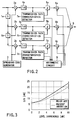
The RAKE receiver 25 has the following arrangement.
FIG. 2 is a circuit block diagram showing the arrangement
of the RAKE receiver 25, and more specifically,
the arrangement for a case in which the radio signals
transmitted through three paths are to be synthesized.
Referring to FIG. 2, the multipath reception
signals that have been received through the antenna
(not shown) and have undergone down-conversion of the
frequencies in the radio unit are respectively input to
multipliers 2a, 2b, and 2c for spread spectrum after
different delay amounts are given to the signals by
delay units 1a and 1b. These multipliers 2a, 2b, and
2c respectively multiply the above multipath reception
signals by the spreading codes generated by a spreading
code generator 3. With this operation, the reception
signals from the respective paths are separated.
These reception signals are respectively integrated
by integral damping filters 4a, 4b, and 4c for
a 1-symbol interval. The resultant integral outputs
are respectively input to weighting multipliers 6a, 6b,
and 6c through phase shifters 5a, 5b, and 5c.
The above integral outputs are also input to
transmission channel characteristics detectors 7a, 7b,
and 7c, respectively. The transmission channel
characteristics detectors 7a, 7b, and 7c detect pieces
of amplitude information and phase difference information
as the transmission channel characteristics of the
respective paths. The pieces of phase difference
information are supplied to the phase shifters 5a, 5b,
and 5c. The phase shifters 5a, 5b, and 5c perform
phase adjustment to match the phases of the respective
integral outputs with each other in accordance with the
pieces of phase difference information.
The pieces of amplitude information of paths P1,
P2, and P3 which are detected by the transmission
channel characteristics detectors 7a, 7b, and 7c are
input to an arithmetic circuit 9. The arithmetic
circuit 9 calculates weighting coefficients for the
respective paths P1, P2, and P3 on the basis of the
pieces of amplitude information of the paths P1, P2,
and P3, detected by the transmission channel
characteristics detectors 7a, 7b, and 7c, and supplies
the calculated weighting coefficients to the weighting
multipliers 6a, 6b, and 6c. Each weighting coefficient
is calculated by using not only the amplitude information
of a corresponding one of the paths P1, P2, and P3
but also the pieces of amplitude information of the two
remaining paths.
Letting R1, R2, and R3 be the amplitudes detected
on the respective paths P1, P2, and P3 by the transmission
channel characteristics detectors 7a, 7b, and 7c,
weighting coefficients W1, W2, and W3 for the paths P1,
P2, and P3 are given by
where f() is a function.
Note that if the function is represented by
path diversity synthesis becomes maximum ratio
synthesis because the transmission channel characteristics
of the respective paths P1, P2, and P3 are
proportional to the weighting coefficients. This
function is equivalent to division of the reception
power of each path of interest by the total reception
power. However, the ratios between the weighting
coefficients for the respective paths P1, P2, and P3
are equal to the ratios between the reception powers of
the paths P1, P2, and P3.
In contrast to this, according to the first
embodiment of the present invention, the arithmetic
circuit 9 obtains the signal power for each path on
the basis of the amplitude of the signal from the path
of interest, and also obtains the interference power
for each path on the basis of the amplitudes of the
signals from the remaining paths. The arithmetic
circuit 9 then obtains a weighting coefficient for
each path of interest in accordance with these
calculation results.
Letting
n be the number of paths, and r1, r2,...,
ri,..., rn be the amplitudes of the transmission
channel characteristics of the respective paths,
weighting coefficients w1, w2,..., wi,..., wn are
given by
where A is the proportional constant,
m is the number
of mobile stations or multicodes, and PG is the spread
factor.
With this arrangement, when, for example, the
reception signals from the paths P1, P2, and P3 are
separated by the respective finger circuits of the RAKE
receiver 25, the transmission channel characteristics
detectors 7a, 7b, and 7c respectively detect pieces of
phase difference information and amplitude information
of the reception signals from the paths P1, P2, and P3.
The phase shifters 5a, 5b, and 5c then perform phase
adjustment in accordance with the pieces of phase
difference information.
The pieces of amplitude information detected by
the transmission channel characteristics detectors 7a,
7b, and 7c are input to the arithmetic circuit 9.
The arithmetic circuit 9 calculates the weighting
coefficients w1, w2, and w3 for the respective paths P1,
P2, and P3 according to equation (1). For example,
for the path P1, the signal power of the signal from
the path P1 is obtained from the amplitude r1 of the
reception signal from the path P1, and the interference
power is then obtained from the amplitudes r2 and r3 of
the reception signals from the two remaining paths P2
and P3. The optimal weighting coefficient w1 for the
path P1 is calculated on the basis of these calculated
signal power and interference power.
For each of the remaining paths P2 and P3, the
signal power is obtained from the amplitude of the
reception signal from the corresponding path, and
the interference power for each path is obtained from
the amplitudes of the reception signals form the two
remaining paths in the same manner as described above.
The weighting coefficients w2 and w3 are then
calculated on the basis of these signal powers and
interference powers.
The weighting coefficients w1, w2, and w3 obtained
in this manner are respectively supplied from the
arithmetic circuit 9 to the weighting multipliers 6a,
6b, and 6c. The weighting multipliers 6a, 6b, and 6c
weight the integral outputs from the phase shifters 5a,
5b, and 5c with the above weighting coefficients w1, w2,
and w3. The weighted reception signals from the
respective paths are synthesized into symbols by
a symbol synthesizer 8. The resultant signal is used
to decode the reception data.
As described above, the first embodiment includes
the arithmetic circuit 9 for weighting coefficients.
This arithmetic circuit 9 obtains the signal power for
each path from the amplitude of the reception signal
from the corresponding path, and also obtains the
interference power from the amplitudes of the reception
signals from the two remaining paths. The arithmetic
circuit 9 then calculates the weighting coefficients w1,
w2, and w3 on the basis of the signal powers and the
interference powers.
Even if, therefore, different interference
powers act on the respective paths and hence cannot
be regarded as white noise as in the case of
upstream channels in a CDMA system, optimal weighting
can be performed for each path in consideration of
not only the signal power but also the interference
power. With this, a reception signal having a high
desired-to-undesired signal ratio (D/U) can be obtained.
FIG. 3 shows the relationship between the level
ratio between two paths and the desired-to-undesired
signal ratio (D/U) in a case in which signals are
received by using the RAKE receiver in the present
invention in comparison with a conventional maximum
ratio synthesis method. As is obvious from FIG. 3, the
scheme of the present invention can obtain better D/U
characteristics than the conventional maximum ratio
synthesis method.
The above effects can be obtained in a spread
spectrum communication system having a plurality of
radio stations distributed, in which an arbitrary radio
station performs multicode transmission of data to
another radio station through a multipath transmission
channel.
(Second Embodiment)
In the first embodiment described above, weighting
is performed in consideration of the signal power on
each path and the interference powers from the
remaining paths. Considering the actual application
environment for a CDMA mobile communication system,
the "intercell interference + thermal noise" power must
also be taken into consideration.
In the second embodiment, therefore, weighting
coefficients for the respective paths are obtained in
consideration of the above "intercell interference +
thermal noise" as well. More specifically, letting N
be the "intercell interference + thermal noise" power,
the equation used in an
arithmetic circuit 9 is
expressed as
According to this equation, the "intercell
interference + thermal noise" power N can be
approximately estimated by obtaining the interference
power in the cell from the number of mobile stations
in the cell and subtracting the interference power from
the total reception power obtained from the antennas
of the mobile stations. Alternatively, the power N
may be set in advance on the basis of logic values or
measured values. With this setting, the computation
amount of the arithmetic circuit 9 can be reduced.
In addition, the "intercell interference + thermal
noise" N may be multiplied by a predetermined
coefficient α (for example, α = 0.5 to 1.5) in
consideration of the differences in temporal variation
characteristics of "intra-cell interference" and
"intercell interference + thermal noise".
In a spread spectrum communication system in which
multicode transmission of data is performed between two
radio stations, equation (2) can be used or one radio
station without any modification by setting the
"intercell interference + thermal noise" power from the
other radio station to N.
According to the second embodiment, when the
arithmetic circuit 9 is to calculate the weighting
coefficient for each path, noise power based on
intercell interference or interference from the other
radio station and thermal noise is taken into
consideration, as well as the signal power on each
path and the interference power from the other path.
In a system that is vulnerable to interference from
other cells like a cellular radio station, optimal
weighting can be performed for each cell in accordance
with the actual situation, thereby obtaining a
reception signal with a higher D/U ratio.
(Other Embodiments)
The present invention is not limited to the above
embodiments. For example, in the first embodiment,
one arithmetic circuit 9 is shared among the finger
circuits corresponding to the respective paths, and
this arithmetic circuit 9 calculates the weighting
coefficients for the respective paths by time-division
processing. As shown in FIG. 4, however, arithmetic
circuits 9a, 9b, and 9c may be arranged for the
respective finger circuits corresponding to the
respective paths to independently calculate the
weighting coefficients for the respective paths.
With this arrangement, weighting coefficients can be
calculated at high speed without using any high-speed
arithmetic circuit as compared with the circuit
(FIG. 2) in the first embodiment.
In each embodiment described above, the arithmetic
circuit 9 is arranged independently of the respective
finger circuits. However, the phase shifters 5a, 5b,
and 5c, the weighting multipliers 6a, 6b, and 6c, and
the arithmetic circuit 9 may be integrated into a DSP
(Digital Signal Processor), and phase adjustment,
calculation of weighting coefficients, and
weighting/multiplying processing may be performed
by the DSP.
Obviously, the above arithmetic circuit may be
formed by an LSI together with or independently of
the phase shifters 5a, 5b, and 5c and the weighting
multipliers 6a, 6b, and 6c.
In the second embodiment, the weighting
coefficients for the respective paths are obtained in
consideration of "intercell interference + thermal
noise". However, in a mobile communication system
including only one base station, intercell interference
need not be taken into consideration. In this system,
therefore, the weighting coefficients for the
respective paths may be obtained in consideration of
only thermal noise.
In addition, the arrangement of the RAKE receiver,
the arrangement and arithmetic processing contents of
the arithmetic circuit, the type and arrangement of
communication apparatus using the RAKE receiver, and
the type and arrangement of communication system to
which the present invention is to be applied can be
variously modified within the spirit and scope of the
present invention.