EP0892261A2 - Procédé d'optimalisation de l'épaisseur de pièces de machines ou véhicules - Google Patents
Procédé d'optimalisation de l'épaisseur de pièces de machines ou véhicules Download PDFInfo
- Publication number
- EP0892261A2 EP0892261A2 EP98112424A EP98112424A EP0892261A2 EP 0892261 A2 EP0892261 A2 EP 0892261A2 EP 98112424 A EP98112424 A EP 98112424A EP 98112424 A EP98112424 A EP 98112424A EP 0892261 A2 EP0892261 A2 EP 0892261A2
- Authority
- EP
- European Patent Office
- Prior art keywords
- rim
- machine
- force
- regular
- point
- Prior art date
- Legal status (The legal status is an assumption and is not a legal conclusion. Google has not performed a legal analysis and makes no representation as to the accuracy of the status listed.)
- Withdrawn
Links
- 238000000034 method Methods 0.000 title claims abstract description 19
- 238000005259 measurement Methods 0.000 abstract description 2
- 238000005457 optimization Methods 0.000 description 7
- 238000012360 testing method Methods 0.000 description 5
- 238000004458 analytical method Methods 0.000 description 4
- 238000010586 diagram Methods 0.000 description 3
- 238000013461 design Methods 0.000 description 2
- XAGFODPZIPBFFR-UHFFFAOYSA-N aluminium Chemical compound [Al] XAGFODPZIPBFFR-UHFFFAOYSA-N 0.000 description 1
- 229910052782 aluminium Inorganic materials 0.000 description 1
- 230000000712 assembly Effects 0.000 description 1
- 238000000429 assembly Methods 0.000 description 1
- 238000004364 calculation method Methods 0.000 description 1
- 238000004590 computer program Methods 0.000 description 1
- 238000005520 cutting process Methods 0.000 description 1
- 238000011161 development Methods 0.000 description 1
- 239000000446 fuel Substances 0.000 description 1
- 238000004519 manufacturing process Methods 0.000 description 1
- 239000000463 material Substances 0.000 description 1
- 230000003068 static effect Effects 0.000 description 1
- 230000007704 transition Effects 0.000 description 1
Images

Classifications
-
- G—PHYSICS
- G01—MEASURING; TESTING
- G01M—TESTING STATIC OR DYNAMIC BALANCE OF MACHINES OR STRUCTURES; TESTING OF STRUCTURES OR APPARATUS, NOT OTHERWISE PROVIDED FOR
- G01M5/00—Investigating the elasticity of structures, e.g. deflection of bridges or air-craft wings
- G01M5/0041—Investigating the elasticity of structures, e.g. deflection of bridges or air-craft wings by determining deflection or stress
- G01M5/005—Investigating the elasticity of structures, e.g. deflection of bridges or air-craft wings by determining deflection or stress by means of external apparatus, e.g. test benches or portable test systems
-
- G—PHYSICS
- G01—MEASURING; TESTING
- G01M—TESTING STATIC OR DYNAMIC BALANCE OF MACHINES OR STRUCTURES; TESTING OF STRUCTURES OR APPARATUS, NOT OTHERWISE PROVIDED FOR
- G01M99/00—Subject matter not provided for in other groups of this subclass
- G01M99/002—Thermal testing
Definitions
- the invention relates to a method for optimizing the wall thicknesses of machine or vehicle parts.
- the present invention is therefore based on the problem to create a process with which existing machine and Vehicle parts in terms of their mass quickly and load-related can be optimized.
- components can be analyzed using a stress analysis by deformation assignment, for example in the case of non-linear ones or not clearly understandable burdens regarding their weight can be optimally designed.
- Stress analysis can also be an analysis of the proportion of Deformation work can be used.
- a motor vehicle rim is used as an exemplary embodiment.
- the circumferential bend was the design criterion for a rim used.
- the maximum voltage was in the transition point from the hub area to the rim bowl.
- a commercially available rim becomes Tires mounted.
- the rim area corresponds to between the rim flange and the rim hump of the assembly joint. Possibly the tire is additionally glued there.
- About the on Regular gas pressure inflated tires will then be the rim loading force - for example static - initiated. To becomes a burden corresponding to the real conditions initiated and measured in three axes over the tire contact patch.
- the deformations resulting from the load are in the Rim flange area e.g. mechanically or optically scanned.
- the deformations can also occur with different Loads are registered and evaluated.
- the process allows through a real stress analysis or by analyzing the proportion of the deformation work a maximum weight saving per component with a considerable Shorten development time.
- Figure 1 shows i.a. a device by means of which the process to optimize the wall thickness of a machine and vehicle part can be carried out.
- the optimization object (1) here is a motor vehicle rim made of low-pressure cast aluminum. On the rim (1) is to simulate real load conditions a conventional tire (4) is mounted. The rim (1) and the tire (4) form the test wheel (5).
- the mechanical device comprises three assemblies.
- the first The assembly is a holding device (11) for rigid and torsionally rigid Fixation of the test wheel (5).
- the holding device (11) stands in the embodiment on a base plate (15).
- a force application device (21) arranged at the foot of the holding device (11) at the foot of the holding device (11) at the foot of the holding device (11) at the foot of the holding device (11) at the foot of the holding device (11) at the foot of the holding device (11) at the foot of the holding device (11) at the foot of the holding device (11) at the foot of the holding device (11) is a force application device (21) arranged. With it, the test wheel (5) in radial Direction (z), in the circumferential direction (x) and in the lateral direction (y) be charged.
- the force application device (21) from three management systems that together form a Cartesian Clamp the coordinate system.
- the lower guidance system consists of a mounted on the holding device (11) z-slide (22). There is an x-slide on the z-slide (22) (23) guided, which in turn a y-slide (24) wearing.
- Each carriage (22, 23, 24) is supported on the one that carries it Component (11, 22, 23
- a third assembly a multi-coordinate measuring machine (31) slidably set up.
- the measuring machine (31) can approximately with its stylus (33) the entire rim surface not covered by the tire (4) - at least scan the rim flange area.
- the multi-coordinate measuring machine (31) and the force application device (21) are above signal and control lines (26, 27) and (36, 37) with a computer (41) in connection.
- the rim geometry data, a FEM structure (34) adapted to the rim and a Measurement program for scanning the rim (1) loaded.
- the rim surface in case the contour data in the area the previously defined FEM surface nodes are known, at least partially measured, so the surface contour the unloaded and undeformed rim (1) in the Detect the area of the FEM surface nodes (35).
- the measuring points are marked, e.g. by recording individual crosshairs, the attachment of center holes or sticking measuring aids in the form of small hemispheres.
- marking with the glued on hemispheres to determine a rim point on the individual hemisphere at least four points are measured.
- the force application device (21) After aligning and / or measuring the unloaded Rim (1) the force application device (21) is activated.
- the y-slide (24) lies against the tire (4). All sledges (22 - 24) are used to simulate a selectable, regular Load-adjusted accordingly. Because of the arrangement the tire (4) of the force application device (21) deformed especially in the mountain area and in the rim flange area. Depending on the tire deformation, the highly loaded ones also deform Rim flanges (2, 3).
- the individual force measuring devices deliver those on each slide drive Powers. The latter are on the signal line (27) to the Computer (41) transmitted.
- This rim deformation is measured by means of the measuring machine (31) in the area the FEM surface node (35) was measured.
- the Measuring machine (31) for example 16 measuring points per rim flange (2, 3) on. Each measuring point corresponds to an FEM surface node.
- 4 Measurements carried out. The determined coordinates are as Route information forwarded to the computer (41) and there with the corresponding measuring point coordinates of the unloaded Rim compared to determine the relocations of each Calculate measuring points or the deformations of the rim (1) there.
- the FEM computer program the different stress curves in the rim wall are calculated.
- the stress curves in different cutting planes show zones of different loads in the rim (1).
- the wall thickness can be reduced, without the deformation of the rim (1) comparable load noticeably increased.
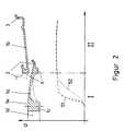
- FIG. 2 shows a diagram showing the voltage curve shows along half a rim cut.
- the new wall thickness shown in dashed lines, reduced so far in the bowl area (1a), that they are proportional to the dashed voltage curve (51) extends.
- the reduction in wall thickness in the Bowl area (1a) depending on rim size and rim material a mass reduction of 10 to 20%.
- a mass reduction of 10 to 20% In addition to lowering the Total vehicle mass, including lower fuel consumption has resulted in a mass reduction of this magnitude a considerable amount of unsprung vehicle mass positive impact on the chassis design and others, it improves driving dynamics.
Landscapes
- Physics & Mathematics (AREA)
- General Physics & Mathematics (AREA)
- Engineering & Computer Science (AREA)
- Aviation & Aerospace Engineering (AREA)
- Tires In General (AREA)
- Force Measurement Appropriate To Specific Purposes (AREA)
- Automobile Manufacture Line, Endless Track Vehicle, Trailer (AREA)
Applications Claiming Priority (2)
| Application Number | Priority Date | Filing Date | Title |
|---|---|---|---|
| DE19730402 | 1997-07-16 | ||
| DE19730402A DE19730402C2 (de) | 1997-07-16 | 1997-07-16 | Verfahren zur Optimierung der Wandstärken von Maschinen- oder Fahrzeugteilen |
Publications (2)
| Publication Number | Publication Date |
|---|---|
| EP0892261A2 true EP0892261A2 (fr) | 1999-01-20 |
| EP0892261A3 EP0892261A3 (fr) | 1999-09-01 |
Family
ID=7835834
Family Applications (1)
| Application Number | Title | Priority Date | Filing Date |
|---|---|---|---|
| EP98112424A Withdrawn EP0892261A3 (fr) | 1997-07-16 | 1998-07-04 | Procédé d'optimalisation de l'épaisseur de pièces de machines ou véhicules |
Country Status (2)
| Country | Link |
|---|---|
| EP (1) | EP0892261A3 (fr) |
| DE (1) | DE19730402C2 (fr) |
Family Cites Families (8)
| Publication number | Priority date | Publication date | Assignee | Title |
|---|---|---|---|---|
| DE3114714A1 (de) * | 1981-04-11 | 1982-10-28 | Fraunhofer-Gesellschaft zur Förderung der angewandten Forschung e.V., 8000 München | "einrichtung zur betriebsaehnlichen pruefung von fahrzeugraedern" |
| DE3141471A1 (de) * | 1981-10-20 | 1983-05-05 | Brown, Boveri & Cie Ag, 6800 Mannheim | Kurzschlussschutzeinrichtung fuer transistoren |
| DE3707102A1 (de) * | 1987-03-05 | 1988-09-15 | Blum Rainer Dr Ing Habil | Verfahren zur bestimmung der elastischen eigenschaften, also der materialqualitaet eines beliebig geformten koerpers |
| DE3824003A1 (de) * | 1988-07-15 | 1989-02-23 | Nsq Hauk Ges Fuer Qualitaetssi | Verfahren zur pruefung von rohrleitungssystemen |
| DE4012501A1 (de) * | 1989-04-28 | 1990-10-31 | Volkswagen Ag | Aus einer radfelge und einer radschuessel zusammengesetztes fahrzeugrad |
| JPH0721221A (ja) * | 1993-06-18 | 1995-01-24 | Sekisui Chem Co Ltd | 雨樋の最適肉厚設計方法 |
| GB9326472D0 (en) * | 1993-12-24 | 1994-02-23 | Ngk Ceramics Europ Sa | Method and apparatus for testing ceramic members |
| DE19548109A1 (de) * | 1995-12-21 | 1997-06-26 | Suedrad Autoraeder | Felge und Verfahren zu ihrer Herstellung |
-
1997
- 1997-07-16 DE DE19730402A patent/DE19730402C2/de not_active Expired - Fee Related
-
1998
- 1998-07-04 EP EP98112424A patent/EP0892261A3/fr not_active Withdrawn
Also Published As
| Publication number | Publication date |
|---|---|
| DE19730402A1 (de) | 1999-02-18 |
| DE19730402C2 (de) | 2000-02-24 |
| EP0892261A3 (fr) | 1999-09-01 |
Similar Documents
| Publication | Publication Date | Title |
|---|---|---|
| DE69903990T2 (de) | Verfahren zur Abschätzung der verschleissbedingten Lebensdauer eines Reifens | |
| EP2136195B1 (fr) | Procédé et dispositif d'essai d'un amortisseur de chocs intégré dans un véhicule automobile | |
| DE60012781T2 (de) | Verfahren zur erfassung des dynamischen verhaltens eines fahrzeugs auf einem prüfstand | |
| EP2425225B1 (fr) | Procédé de contrôle de bogies et banc d'essai/de montage | |
| DE69722887T2 (de) | Vorrichtung und zugehörige Verfahren zum automatischen Prüfen und Analysieren von Reifen | |
| DE112009000488B4 (de) | Testsystem mit Strebenanordnung sowie Verfahren | |
| DE202011101009U1 (de) | Versuchsanlage | |
| EP1181522A1 (fr) | Procede de regulation pour un banc d'essai de roues biaxial servant a simuler des charges de marche et banc d'essai de roues biaxial | |
| DE3544893C2 (fr) | ||
| DE102008041745B4 (de) | Verfahren und Vorrichtung zum Prüfen wenigstens eines Schwingungsdämpfers eines Kraftfahrzeugs im eingebauten Zustand | |
| DE69810435T2 (de) | Verfahren und anordnung zur bestimmung des reifenfüllzustandes | |
| DE69830362T2 (de) | Ein Verfahren zum Voraussagen der Reifenleistung auf Strassen mit Regenrinnen | |
| DE102010015571A1 (de) | System und Verfahren zur Ermittlung des Masseschwerpunktes bei Schienenfahrzeugen | |
| EP0892261A2 (fr) | Procédé d'optimalisation de l'épaisseur de pièces de machines ou véhicules | |
| EP1544589B1 (fr) | Méthode et dispositif pour la détermination des forces verticales actuées sur un véhicule par le courant d'air dans une soufflerie | |
| DE102004030742B4 (de) | Verfahren zur Ermittlung von Referenzgewichten mit einer dynamischen Gleiswaage | |
| DE10260909A1 (de) | Mess- und Richtstation | |
| DE19939549A1 (de) | Prufstand zum Messen der Beulsteifigkeit von Bauteilen | |
| DE10115490C1 (de) | Verfahren und Vorrichtung zum Eichen einer Überfahrwaage | |
| DE2551067A1 (de) | Vorrichtung zum testen von reifen | |
| DE102011086759B4 (de) | Verfahren und Vorrichtung zur Ermittlung von Radlasten von Schienenfahrzeugen | |
| DE3873901T4 (de) | Vorrichtung zur Messung des Gewichts. | |
| EP3037801B1 (fr) | Procede et dispositif de determination de la force d'appui dynamique d'une roue | |
| EP0905591B1 (fr) | Dispositif pour évaluer la position d'un outil s'approchant dans une machine de formage | |
| DE10233534B4 (de) | Verfahren zur Luftdruckkontrolle von luftbereiften Fahrzeugrädern |
Legal Events
| Date | Code | Title | Description |
|---|---|---|---|
| PUAI | Public reference made under article 153(3) epc to a published international application that has entered the european phase |
Free format text: ORIGINAL CODE: 0009012 |
|
| AK | Designated contracting states |
Kind code of ref document: A2 Designated state(s): DE FR GB IT |
|
| AX | Request for extension of the european patent |
Free format text: AL;LT;LV;MK;RO;SI |
|
| RAP1 | Party data changed (applicant data changed or rights of an application transferred) |
Owner name: DAIMLERCHRYSLER AG |
|
| PUAL | Search report despatched |
Free format text: ORIGINAL CODE: 0009013 |
|
| AK | Designated contracting states |
Kind code of ref document: A3 Designated state(s): AT BE CH CY DE DK ES FI FR GB GR IE IT LI LU MC NL PT SE |
|
| AX | Request for extension of the european patent |
Free format text: AL;LT;LV;MK;RO;SI |
|
| 17P | Request for examination filed |
Effective date: 19990729 |
|
| AKX | Designation fees paid |
Free format text: DE FR GB IT |
|
| STAA | Information on the status of an ep patent application or granted ep patent |
Free format text: STATUS: THE APPLICATION IS DEEMED TO BE WITHDRAWN |
|
| 18D | Application deemed to be withdrawn |
Effective date: 20020201 |