EP0892261A2 - Method for optimizing the thickness of machine or vehicle parts - Google Patents
Method for optimizing the thickness of machine or vehicle parts Download PDFInfo
- Publication number
- EP0892261A2 EP0892261A2 EP98112424A EP98112424A EP0892261A2 EP 0892261 A2 EP0892261 A2 EP 0892261A2 EP 98112424 A EP98112424 A EP 98112424A EP 98112424 A EP98112424 A EP 98112424A EP 0892261 A2 EP0892261 A2 EP 0892261A2
- Authority
- EP
- European Patent Office
- Prior art keywords
- rim
- machine
- force
- wall thickness
- tire
- Prior art date
- Legal status (The legal status is an assumption and is not a legal conclusion. Google has not performed a legal analysis and makes no representation as to the accuracy of the status listed.)
- Withdrawn
Links
Images

Classifications
-
- G—PHYSICS
- G01—MEASURING; TESTING
- G01M—TESTING STATIC OR DYNAMIC BALANCE OF MACHINES OR STRUCTURES; TESTING OF STRUCTURES OR APPARATUS, NOT OTHERWISE PROVIDED FOR
- G01M5/00—Investigating the elasticity of structures, e.g. deflection of bridges or air-craft wings
- G01M5/0041—Investigating the elasticity of structures, e.g. deflection of bridges or air-craft wings by determining deflection or stress
- G01M5/005—Investigating the elasticity of structures, e.g. deflection of bridges or air-craft wings by determining deflection or stress by means of external apparatus, e.g. test benches or portable test systems
-
- G—PHYSICS
- G01—MEASURING; TESTING
- G01M—TESTING STATIC OR DYNAMIC BALANCE OF MACHINES OR STRUCTURES; TESTING OF STRUCTURES OR APPARATUS, NOT OTHERWISE PROVIDED FOR
- G01M99/00—Subject matter not provided for in other groups of this subclass
- G01M99/002—Thermal testing
Landscapes
- Physics & Mathematics (AREA)
- General Physics & Mathematics (AREA)
- Engineering & Computer Science (AREA)
- Aviation & Aerospace Engineering (AREA)
- Tires In General (AREA)
- Automobile Manufacture Line, Endless Track Vehicle, Trailer (AREA)
- Force Measurement Appropriate To Specific Purposes (AREA)
Abstract
Description
Die Erfindung betrifft ein Verfahren zur Optimierung der Wandstärken von Maschinen- oder Fahrzeugteilen.The invention relates to a method for optimizing the wall thicknesses of machine or vehicle parts.
Viele komplizierte und/oder sicherheitstechnisch relevante Bauteile werden vor ihrer Realisierung mit Hilfe verschiedener Berechnungsverfahren ausgelegt bzw. dimensioniert. Die fertigen Bauteile werden anschließend im Versuch getestet und dann entweder für die Serienfertigung freigegeben oder nochmals überarbeitet. Eine belastungsbezogene Gewichtsoptimierung unterbleibt oft.Many complicated and / or safety-relevant components are implemented using various calculation methods designed or dimensioned. The finished Components are then tested in the test and then either released for series production or revised again. There is no load-related weight optimization often.
Der vorliegenden Erfindung liegt daher das Problem zugrunde, ein Verfahren zu schaffen, mit dem vorhandene Maschinen- und Fahrzeugteile bezüglich ihrer Masse schnell und belastungsbezogen optimiert werden können.The present invention is therefore based on the problem to create a process with which existing machine and Vehicle parts in terms of their mass quickly and load-related can be optimized.
Das Problem wird u.a. mit den Merkmalen des Hauptanspruchs gelöst. Bei der Anwendung des Verfahrens zur Optimierung der Wandstärken von Maschinen- oder Fahrzeugteilen wird das zu optimierende Bauteil, das auch aus mehreren Einzelteilen bestehen kann, an der regulären Montagefuge oder der oder den regulären Befestigungsstellen in einer Haltevorrichtung fixiert. Daraufhin wird das Maschinen- oder Fahrzeugteil an mindestens einer regulären Krafteinleitungsstelle zumindest einachsig mechanisch und/oder thermisch belastet. Anschließend oder gleichzeitig werden an einer Vielzahl von verschiedenen Meßstellen, die als Knoten in einer FEM-Struktur zwischen der Montagefuge oder der oder den Befestigungsstellen und der Krafteinleitungsstelle angeordnet sind, die aus der Krafteinleitung resultierenden Verformungen meßtechnisch erfaßt. Unter Zuhilfenahme der nach Betrag und Richtung bekannten einzelnen Verformungen wird der Spannungsverlauf und/oder der Anteil der Formänderung im Bauteil ermittelt und entweder zum ermittelten Spannungsverlauf und/oder zum ermittelten Formänderungsanteil ein zumindest partiell annähernd proportionaler Wandstärkenverlauf oder eine minimale Konstantwandstärke gestaltet.The problem is solved with the features of the main claim. When using the procedure to optimize the Wall thicknesses of machine or vehicle parts will be optimized Component that also consist of several individual parts can, at the regular assembly joint or the regular Fastening points fixed in a holding device. Thereupon the machine or vehicle part is attached to at least one regular force application point at least uniaxial mechanical and / or thermally stressed. Then or at the same time are used at a variety of different measuring points Knot in an FEM structure between the assembly joint or the or the attachment points and the force application point are the deformations resulting from the application of force metrologically recorded. With the help of the amount and the direction of known individual deformations Stress curve and / or the proportion of the change in shape in the component determined and either to the determined voltage curve and / or at least partially to the determined change in shape approximately proportional wall thickness or a minimal Constant wall thickness designed.
Mit dem Verfahren können Bauteile anhand einer Spannungsanalyse durch Verformungszuordnung, beispielsweise bei nicht linearen oder nicht eindeutig nachvollziehbaren Belastungen, bezüglich ihres Gewichtes optimal ausgelegt werden. Anstelle der Spannungsanalyse kann auch eine Analyse des Anteils der Formänderungsarbeit verwendet werden.With the method, components can be analyzed using a stress analysis by deformation assignment, for example in the case of non-linear ones or not clearly understandable burdens regarding their weight can be optimally designed. Instead of Stress analysis can also be an analysis of the proportion of Deformation work can be used.
Als Ausführungsbeispiel wird eine Kraftfahrzeugfelge verwendet. Bisher wurde für eine Felge die Umlaufbiegung als Auslegungskriterium herangezogen. Demzufolge lag die maximale Spannung in der Übergangsstelle vom Nabenbereich zur Felgenschüssel.A motor vehicle rim is used as an exemplary embodiment. Until now, the circumferential bend was the design criterion for a rim used. As a result, the maximum voltage was in the transition point from the hub area to the rim bowl.
Beim neuen Verfahren wird auf die Felge ein handelsüblicher Reifen montiert. Dabei entspricht der Felgenbereich zwischen dem Felgenhorn und dem Felgenhump der Montagefuge. Gegebenenfalls wird der Reifen dort zusätzlich verklebt. Über den auf regulärem Gasdruck aufgepumpten Reifen wird dann die die Felge belastende Kraft - beispielsweise statisch - eingeleitet. Dazu wird eine den realen Verhältnissen entsprechende Belastung dreiachsig über die Reifenaufstandsfläche eingeleitet und gemessen.With the new process, a commercially available rim becomes Tires mounted. The rim area corresponds to between the rim flange and the rim hump of the assembly joint. Possibly the tire is additionally glued there. About the on Regular gas pressure inflated tires will then be the rim loading force - for example static - initiated. To becomes a burden corresponding to the real conditions initiated and measured in three axes over the tire contact patch.
Die sich unter der Belastung ergebenden Verformungen werden im Bereich der Felgenhörner z.B. mechanisch oder optisch abgetastet. Dabei können die Verformungen auch bei unterschiedlichen Belastungen registriert und ausgewertet werden.The deformations resulting from the load are in the Rim flange area e.g. mechanically or optically scanned. The deformations can also occur with different Loads are registered and evaluated.
Mit Hilfe der Geometriedaten, der FEM-Struktur und den Zwangsverformungen wird der Spannungsverlauf in den einzelnen Felgenschnitten berechnet. Abschließend wird an Feigenstellen mit geringer Belastung die Wandstärke reduziert. Werden größere Änderungen vorgenommen, wird gegebenenfalls die Felge nochmals berechnet oder das Optimierungsverfahren an einem neuen Modell wiederholt.With the help of the geometry data, the FEM structure and the forced deformations the stress curve in the individual rim cuts calculated. Finally, at fig places with less Load reduces the wall thickness. Be major changes If necessary, the rim will be recalculated or the optimization process on a new model repeated.
Das Verfahren erlaubt u.a. durch eine reale Spannungsanalyse oder durch eine Analyse des Anteils der Formänderungsarbeit eine maximale Gewichtseinsparung pro Bauteil bei einer erheblichen Verkürzung der Entwicklungsdauer.Among other things, the process allows through a real stress analysis or by analyzing the proportion of the deformation work a maximum weight saving per component with a considerable Shorten development time.
Weitere Einzelheiten der Erfindung ergeben sich aus der nachfolgenden Beschreibung einer schematisch dargestellten Ausführungsform:
- Figur 1:
- Vorrichtung zur Anwendung des Verfahrens zur Wandstärkenoptimierung bei einer Kraftfahrzeugfelge;
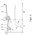
- Figur 2:
- Spannungsverlauf in einem Querschnitt der Kraftfahrzeugfelge.
- Figure 1:
- Device for using the method for wall thickness optimization in a motor vehicle rim;
- Figure 2:
- Stress curve in a cross section of the motor vehicle rim.
Figur 1 zeigt u.a. eine Vorrichtung mit deren Hilfe das Verfahren zur Optimierung der Wandstärken eines Maschinen- und Fahrzeugteils durchgeführt werden kann. Das Optimierungsobjekt (1) ist hier eine Kraftfahrzeugfelge aus Aluminiumniederdruckguß. Auf der Felge (1) ist zur Simulation realer Belastungsverhältnisse ein konventioneller Reifen (4) montiert. Die Felge (1) und der Reifen (4) bilden das Testrad (5).Figure 1 shows i.a. a device by means of which the process to optimize the wall thickness of a machine and vehicle part can be carried out. The optimization object (1) here is a motor vehicle rim made of low-pressure cast aluminum. On the rim (1) is to simulate real load conditions a conventional tire (4) is mounted. The rim (1) and the tire (4) form the test wheel (5).
Die mechanische Vorrichtung umfaßt drei Baugruppen. Die erste Baugruppe ist eine Haltevorrichtung (11) zur steifen und drehstarren Fixierung des Testrades (5). Die Haltevorrichtung (11) steht im Ausführungsbeispiel auf einer Grundplatte (15).The mechanical device comprises three assemblies. The first The assembly is a holding device (11) for rigid and torsionally rigid Fixation of the test wheel (5). The holding device (11) stands in the embodiment on a base plate (15).
Am Fuß der Haltevorrichtung (11) ist eine Krafteinleitungsvorrichtung (21) angeordnet. Mit ihr kann das Testrad (5) in radialer Richtung (z), in Umfangsrichtung (x) und in Seitenrichtung (y) belastet werden. Dazu besteht die Krafteinleitungsvorrichtung (21) aus drei Führungssystemen, die gemeinsam ein kartesisches Koordinatensystem aufspannen. Das untere Führungssystem besteht aus einem an der Haltevorrichtung (11) gelagerten z-Schlitten (22). Auf dem z-Schlitten (22) ist ein x-Schlitten (23) geführt, der wiederum einen y-Schlitten (24) trägt. Jeder Schlitten (22, 23, 24) stützt sich an dem ihn tragenden Bauteil (11, 22, 23) mittels eines Verstellantriebes ab. In jeweils einer Anlenkung des jeweiligen Verstellantriebes ist eine Kraftmeßeinrichtung angeordnet. Die Verstellantriebe und die Kraftmeßeinrichtungen sind hier nicht dargestellt.At the foot of the holding device (11) is a force application device (21) arranged. With it, the test wheel (5) in radial Direction (z), in the circumferential direction (x) and in the lateral direction (y) be charged. For this purpose, there is the force application device (21) from three management systems that together form a Cartesian Clamp the coordinate system. The lower guidance system consists of a mounted on the holding device (11) z-slide (22). There is an x-slide on the z-slide (22) (23) guided, which in turn a y-slide (24) wearing. Each carriage (22, 23, 24) is supported on the one that carries it Component (11, 22, 23) by means of an adjustment drive. In each case there is a linkage of the respective adjustment drive a force measuring device is arranged. The actuators and the force measuring devices are not shown here.
Auf der Grundplatte (15) ist als dritte Baugruppe beispielsweise eine Mehrkoordinatenmeßmachine (31) verschiebbar aufgestellt. Die Meßmaschine (31) kann mit ihrem Taststift (33) annähernd die gesamte vom Reifen (4) nicht bedeckte Felgenoberfläche - zumindest jedoch den Felgenhornbereich - abtasten. On the base plate (15) is, for example, a third assembly a multi-coordinate measuring machine (31) slidably set up. The measuring machine (31) can approximately with its stylus (33) the entire rim surface not covered by the tire (4) - at least scan the rim flange area.
Die Mehrkoordinatenmeßmaschine (31) und die Krafteinleitungsvorrichtung (21) stehen über Signal- und Steuerleitungen (26, 27) und (36, 37) mit einem Rechner (41) in Verbindung.The multi-coordinate measuring machine (31) and the force application device (21) are above signal and control lines (26, 27) and (36, 37) with a computer (41) in connection.
Zur Durchführung des Optimierungsverfahrens wird eine vorhandene Felge (1) verwendet. Sie wird zusammen mit dem montierten Reifen (4) an der Haltevorrichtung (11) mit Hilfe von Radschrauben so befestigt, wie das in der Regel auch am Bremsscheibentopf oder der Bremstrommel eines üblichen Kraftfahrzeugs erfolgt.An existing one is used to carry out the optimization process Rim (1) used. It is assembled together with the Tire (4) on the holding device (11) using wheel bolts attached in the same way as that to the brake disc chamber or the brake drum of a conventional motor vehicle he follows.
Parallel hierzu werden im Rechner (41) die Felgengeometriedaten, eine an die Felge angepaßte FEM-Struktur (34) und ein Meßprogramm für das Abtasten der Felge (1) geladen. Nach dem Ausrichten der Meßmaschine (31) gegenüber der Felge (1) wird die Felgenoberfläche für den Fall, daß die Konturdaten im Bereich der vorher festgelegten FEM-Oberflächenknoten noch nicht bekannt sind, zumindest partiell vermessen, um so die Oberflächenkontur der unbelasteten und nicht verformten Felge (1) im Bereich der FEM-Oberflächenknoten (35) zu erfassen. Gegebenenfalls werden die Meßstellen markiert, z.B. durch das Aufzeichnen einzelner Fadenkreuze, das Anbringen von Zentrierbohrungen oder das Aufkleben von Meßhilfen in Form von kleinen Halbkugeln. Bei der Markierung mit den aufgeklebten Halbkugeln müssen zur Ermittlung eines Felgenpunktes an der einzelnen Halbkugel mindstens vier Punkte gemessen werden.At the same time, the rim geometry data, a FEM structure (34) adapted to the rim and a Measurement program for scanning the rim (1) loaded. After this Aligning the measuring machine (31) with respect to the rim (1) the rim surface in case the contour data in the area the previously defined FEM surface nodes are known, at least partially measured, so the surface contour the unloaded and undeformed rim (1) in the Detect the area of the FEM surface nodes (35). Possibly the measuring points are marked, e.g. by recording individual crosshairs, the attachment of center holes or sticking measuring aids in the form of small hemispheres. When marking with the glued on hemispheres to determine a rim point on the individual hemisphere at least four points are measured.
Nach dem Ausrichten und/oder Vermessen der unbelasteten Felge (1) wird die Krafteinleitungsvorrichtung (21) aktiviert. Der y-Schlitten (24) legt sich am Reifen (4) an. Alle Schlitten (22 - 24) werden für die Simulation eines wählbaren, regulären Lastfalls entsprechend eingestellt. Aufgrund der Anordnung der Krafteinleitungsvorrichtung (21) wird der Reifen (4) besonders im Latschbereich und im Felgenhornbereich deformiert. Entsprechend der Reifenverformung verformen sich auch die hochbelasteten Felgenhörner (2, 3). Die einzelnen Kraftmeßeinrichtungen liefern die an jedem Schlittenantrieb anliegenden Kräfte. Letztere werden über die Signalleitung (27) an den Rechner (41) übermittelt.After aligning and / or measuring the unloaded Rim (1) the force application device (21) is activated. The y-slide (24) lies against the tire (4). All sledges (22 - 24) are used to simulate a selectable, regular Load-adjusted accordingly. Because of the arrangement the tire (4) of the force application device (21) deformed especially in the mountain area and in the rim flange area. Depending on the tire deformation, the highly loaded ones also deform Rim flanges (2, 3). The individual force measuring devices deliver those on each slide drive Powers. The latter are on the signal line (27) to the Computer (41) transmitted.
Diese Felgenverformung wird mittels der Meßmaschine (31) im Bereich der FEM-Oberflächenknoten (35) gemessen. Dazu fährt die Meßmaschine (31) beispielsweise pro Felgenhorn (2, 3) 16 Meßstellen an. Jede Meßstelle entspricht einem FEM-Oberflächenknoten. Bei einer Halbkugelmarkierung werden pro Meßstelle 4 Messungen durchgeführt. Die ermittelten Koordinaten werden als Weginformationen an den Rechner (41) weitergeleitet und dort mit den entsprechenden Meßstellenkoordinaten der unbelasteten Felge verglichen, um daraus die Verlagerungen der einzelnen Meßstellen bzw. die dortigen Verformungen der Felge (1) zu errechnen.This rim deformation is measured by means of the measuring machine (31) in the area the FEM surface node (35) was measured. To do this, the Measuring machine (31), for example 16 measuring points per rim flange (2, 3) on. Each measuring point corresponds to an FEM surface node. With a hemisphere marking, 4 Measurements carried out. The determined coordinates are as Route information forwarded to the computer (41) and there with the corresponding measuring point coordinates of the unloaded Rim compared to determine the relocations of each Calculate measuring points or the deformations of the rim (1) there.
Mit Hilfe dieser Verformungswerte werden vom FEM-Rechenprogramm die verschiedenen Spannungsverläufe in der Felgenwandung berechnet. Die Spannungsverläufe in verschiedenen Schnittebenen zeigen in der Felge (1) Zonen unterschiedlicher Belastung. In den weniger belasteten Zonen (7), in denen eine niedrigere Vergleichsspannung auftritt, kann die Wandstärke verringert werden, ohne daß sich dadurch die Verformung der Felge (1) bei vergleichbarer Last merkbar vergrößert.With the help of these deformation values the FEM computer program the different stress curves in the rim wall are calculated. The stress curves in different cutting planes show zones of different loads in the rim (1). In the less stressed zones (7), in which a lower reference voltage occurs, the wall thickness can be reduced, without the deformation of the rim (1) comparable load noticeably increased.
Ein Programm zur Optimierung der Felgenmasse errechnet für die einzelnen geringer belasteten Zonen neue, dünnere Wandstärken. In Figur 2 ist ein Diagramm dargestellt, das den Spannungsverlauf entlang eines halben Felgenschnittes zeigt. Zur einfacheren Darstellung des Spannungsverlaufs sind der Schüsselbereich (1a) und der Felgenbettbereich (1b) derselben Felge (1) nebeneinander aufgezeichnet und oberhalb der Kurven (51, 52) dargestellt. Beide Bereiche (1a) und (1b) gehen an der Schnittstelle "A" ineinander über. A program to optimize the rim mass is calculated for the individual, less stressed zones new, thinner wall thicknesses. FIG. 2 shows a diagram showing the voltage curve shows along half a rim cut. For simpler Representation of the voltage curve are the bowl area (1a) and the rim bed area (1b) of the same rim (1) recorded side by side and above the curves (51, 52) shown. Both areas (1a) and (1b) go at the interface "A" over each other.
In dem Diagrammbereich I, in dem die Felgenschüssel gezeigt ist, sind zwei Spannungsverläufe (51, 52) idealisiert dargestellt. Der gepunktet gezeichnete Spannungsverlauf (52) entspricht der gepunkteten Felgenkontur, wie sie bisher gebaut wurde. Der Spannungsverlauf (52) steigt nach dem Lochkreis (1e) allmählich bis zur Schnittstelle "A" an. Im Felgenbettbereich (1b), vgl. Diagrammbereich II, erreicht der Spannungsverlauf seinen Maximalwert. Letzerer liegt erheblich höher als die durchschnittliche Vergleichsspannung im Schüsselbereich (1a).In the diagram area I, in which the rim bowl is shown , two voltage profiles (51, 52) are idealized. The dotted voltage curve (52) corresponds the dotted rim contour as it was built up to now has been. The voltage curve (52) increases after the bolt circle (1e) gradually up to interface "A". In the rim bed area (1b), cf. Diagram area II, the voltage curve reaches its maximum value. The latter is considerably higher than the average reference voltage in the bowl area (1a).
Mit dem neuen Optimierungsverfahren wird die neue Wandstärke, gestrichelt dargestellt, im Schüsselbereich (1a) soweit reduziert, daß sie sich zumindest abschnittsweise proportional zum gestrichelten Spannungsverlauf (51) erstreckt. Beim Ausführungsbeispiel ergibt sich durch die Wandstärkenverringerung im Schüsselbereich (1a) je nach Felgengröße und Felgenwerkstoff eine Massenreduktion von 10 bis 20 %. Neben dieser Senkung der Fahrzeuggesamtmasse, die u.a. einen geringeren Kraftstoffverbrauch bewirkt, hat eine Massenreduktion in dieser Größenordnung an der ungefederten Fahrzeugmasse zum einen eine erhebliche, positive Auswirkung auf die Fahrwerksauslegung und zum anderen verbessert sie die Fahrdynamik. With the new optimization process, the new wall thickness, shown in dashed lines, reduced so far in the bowl area (1a), that they are proportional to the dashed voltage curve (51) extends. In the embodiment results from the reduction in wall thickness in the Bowl area (1a) depending on rim size and rim material a mass reduction of 10 to 20%. In addition to lowering the Total vehicle mass, including lower fuel consumption has resulted in a mass reduction of this magnitude a considerable amount of unsprung vehicle mass positive impact on the chassis design and others, it improves driving dynamics.
- 11
- Optimierungsobjekt, Kraftfahrzeugfelge, FelgeOptimization object, motor vehicle rim, rim
- 1a1a
- SchüsselbereichBowl area
- 1b1b
- FelgenbettbereichRim bed area
- 1c1c
- NabenflanschbereichHub flange area
- 1d1d
- MittenlochCenter hole
- 1e1e
- Lochkreis für die FelgenbefestigungsmittelBolt circle for the rim fasteners
- 2, 32, 3
- Felgenhörner; innen, außenRim flanges; inside Outside
- 44th
- Reifentires
- 55
- TestradTest bike
- 66
- MontagefugeAssembly joint
- 77
- Zonen gerinerer BelastungZones of less stress
- 99
- KrafteinleitungsstelleForce application point
- 1111
- HaltevorrichtungHolding device
- 1515
- GrundplatteBase plate
- 2121
- KrafteinleitungsvorrichtungForce application device
- 2222
- z-Schlittenz-slide
- 2323
- x-Schlittenx-slide
- 2424th
- y-Schlitteny-carriage
- 2626
- Steuerleitungen für die SchlittenantriebeControl lines for the slide drives
- 2727
- Kraftsignalleitungen von den KraftmeßeinrichtungenForce signal lines from the force measuring devices
- 3131
- Mehrkoordinatenmeßmachine, MeßmaschineMulti-coordinate measuring machine, measuring machine
- 3333
- TaststiftStylus
- 3434
- FEM-StrukturFEM structure
- 3535
- Meßstellen, FEM-Oberflächenknoten Measuring points, FEM surface nodes
- 3636
- Steuerleitungen für die MeßmaschinenantriebeControl lines for the measuring machine drives
- 3737
- Signalleitungen für die WeginformationenSignal lines for route information
- 4141
- Rechnercomputer
- 51, 5251, 52
- SpannungsverlaufskurveStress curve
Claims (5)
Applications Claiming Priority (2)
| Application Number | Priority Date | Filing Date | Title |
|---|---|---|---|
| DE19730402A DE19730402C2 (en) | 1997-07-16 | 1997-07-16 | Process for optimizing the wall thickness of machine or vehicle parts |
| DE19730402 | 1997-07-16 |
Publications (2)
| Publication Number | Publication Date |
|---|---|
| EP0892261A2 true EP0892261A2 (en) | 1999-01-20 |
| EP0892261A3 EP0892261A3 (en) | 1999-09-01 |
Family
ID=7835834
Family Applications (1)
| Application Number | Title | Priority Date | Filing Date |
|---|---|---|---|
| EP98112424A Withdrawn EP0892261A3 (en) | 1997-07-16 | 1998-07-04 | Method for optimizing the thickness of machine or vehicle parts |
Country Status (2)
| Country | Link |
|---|---|
| EP (1) | EP0892261A3 (en) |
| DE (1) | DE19730402C2 (en) |
Citations (4)
| Publication number | Priority date | Publication date | Assignee | Title |
|---|---|---|---|---|
| DE3114714A1 (en) * | 1981-04-11 | 1982-10-28 | Fraunhofer-Gesellschaft zur Förderung der angewandten Forschung e.V., 8000 München | Device for realistic testing of vehicle wheels |
| DE3707102A1 (en) * | 1987-03-05 | 1988-09-15 | Blum Rainer Dr Ing Habil | Method of determining the electrical properties, that is to say the material quality, of a body having any shape whatsoever |
| EP0350614A1 (en) * | 1988-07-15 | 1990-01-17 | Nsq- Hauk Gesellschaft Fuer Qualitaetssicherung Mbh | Testing method for tubings |
| JPH0721221A (en) * | 1993-06-18 | 1995-01-24 | Sekisui Chem Co Ltd | Optimum thickness design method for gutter |
Family Cites Families (4)
| Publication number | Priority date | Publication date | Assignee | Title |
|---|---|---|---|---|
| DE3141471A1 (en) * | 1981-10-20 | 1983-05-05 | Brown, Boveri & Cie Ag, 6800 Mannheim | Anti-short-circuit device for transistors |
| DE4012501A1 (en) * | 1989-04-28 | 1990-10-31 | Volkswagen Ag | Two part wheel for pneumatic tyre - has thin wall inner section welded to thicker outer section |
| GB9326472D0 (en) * | 1993-12-24 | 1994-02-23 | Ngk Ceramics Europ Sa | Method and apparatus for testing ceramic members |
| DE19548109A1 (en) * | 1995-12-21 | 1997-06-26 | Suedrad Autoraeder | Rim and process for its manufacture |
-
1997
- 1997-07-16 DE DE19730402A patent/DE19730402C2/en not_active Expired - Fee Related
-
1998
- 1998-07-04 EP EP98112424A patent/EP0892261A3/en not_active Withdrawn
Patent Citations (4)
| Publication number | Priority date | Publication date | Assignee | Title |
|---|---|---|---|---|
| DE3114714A1 (en) * | 1981-04-11 | 1982-10-28 | Fraunhofer-Gesellschaft zur Förderung der angewandten Forschung e.V., 8000 München | Device for realistic testing of vehicle wheels |
| DE3707102A1 (en) * | 1987-03-05 | 1988-09-15 | Blum Rainer Dr Ing Habil | Method of determining the electrical properties, that is to say the material quality, of a body having any shape whatsoever |
| EP0350614A1 (en) * | 1988-07-15 | 1990-01-17 | Nsq- Hauk Gesellschaft Fuer Qualitaetssicherung Mbh | Testing method for tubings |
| JPH0721221A (en) * | 1993-06-18 | 1995-01-24 | Sekisui Chem Co Ltd | Optimum thickness design method for gutter |
Non-Patent Citations (1)
| Title |
|---|
| PATENT ABSTRACTS OF JAPAN vol. 095, no. 004, 31. Mai 1995 & JP 07 021221 A (SEKISUI CHEM CO LTD), 24. Januar 1995 * |
Also Published As
| Publication number | Publication date |
|---|---|
| DE19730402A1 (en) | 1999-02-18 |
| EP0892261A3 (en) | 1999-09-01 |
| DE19730402C2 (en) | 2000-02-24 |
Similar Documents
| Publication | Publication Date | Title |
|---|---|---|
| EP2425225B1 (en) | Test method for bogies as well as test stand and assembly stand | |
| DE112009000488B4 (en) | Test system with strut arrangement and method | |
| EP0226981B1 (en) | Procedure and device for checking the under-carriage of a vehicle | |
| EP2069714B1 (en) | Method for measuring the chassis of a motor vehicle, device for measuring a chassis and motor vehicle testing unit | |
| EP2136195A2 (en) | Method and device for testing an installed shock absorber of a motor vehicle | |
| DE102008018076B4 (en) | System for measuring loads during wheel / rail contact of rail vehicles | |
| EP1181522A1 (en) | Control method for a bi-axial wheel test bench for simulating driving stresses and a bi-axial wheel test bench | |
| DE202011101009U1 (en) | test facility | |
| EP1610103B1 (en) | Method of determining reference weights by means of a dynamic railway cars scale. | |
| DE3544893C2 (en) | ||
| DE10132032A1 (en) | Determination of vehicle axle misalignment and prediction of tire wear by continuous measurement of axle transverse and vertical acceleration and use of the measurements in mathematical equations to indicate misalignment | |
| DE69830362T2 (en) | A method of predicting tire performance on roads with gutters | |
| EP0892261A2 (en) | Method for optimizing the thickness of machine or vehicle parts | |
| EP1544589B1 (en) | Method and apparatus for determining vertical forces acting on a vehicle at wind flow in a wind tunnel | |
| DE4442980A1 (en) | Tyre contour determining method for rubber tyre vulcanisation mfr. process | |
| DE2551067A1 (en) | DEVICE FOR TESTING TIRES | |
| DE10260909A1 (en) | Measurement and correction station for motor vehicle doors comprises numbers of measurement and correction devices together so that door defects can be individually corrected | |
| DE19939549A1 (en) | Test stand for measuring buckling strength e,g. of vehicle body components, with test head traversing along x and y axes | |
| DE102011086759B4 (en) | Method and device for determining wheel loads of rail vehicles | |
| DE10115490C1 (en) | Calibration method for rail vehicle weighing device uses comparison of static and dynamic weighing values obtained for reference vehicle for calibration for dynamic weighing | |
| DE10346537B4 (en) | Measuring wheel for rail vehicles | |
| DE3814646C2 (en) | Device for checking motor vehicle tires | |
| EP0905591B1 (en) | Device for evaluating the position of an approaching tool in a forming machine | |
| DE10233534B4 (en) | Method for controlling the air pressure of pneumatic vehicle wheels | |
| DE102022208511A1 (en) | Production line and method for testing the brakes of a motor vehicle in the production line |
Legal Events
| Date | Code | Title | Description |
|---|---|---|---|
| PUAI | Public reference made under article 153(3) epc to a published international application that has entered the european phase |
Free format text: ORIGINAL CODE: 0009012 |
|
| AK | Designated contracting states |
Kind code of ref document: A2 Designated state(s): DE FR GB IT |
|
| AX | Request for extension of the european patent |
Free format text: AL;LT;LV;MK;RO;SI |
|
| RAP1 | Party data changed (applicant data changed or rights of an application transferred) |
Owner name: DAIMLERCHRYSLER AG |
|
| PUAL | Search report despatched |
Free format text: ORIGINAL CODE: 0009013 |
|
| AK | Designated contracting states |
Kind code of ref document: A3 Designated state(s): AT BE CH CY DE DK ES FI FR GB GR IE IT LI LU MC NL PT SE |
|
| AX | Request for extension of the european patent |
Free format text: AL;LT;LV;MK;RO;SI |
|
| 17P | Request for examination filed |
Effective date: 19990729 |
|
| AKX | Designation fees paid |
Free format text: DE FR GB IT |
|
| STAA | Information on the status of an ep patent application or granted ep patent |
Free format text: STATUS: THE APPLICATION IS DEEMED TO BE WITHDRAWN |
|
| 18D | Application deemed to be withdrawn |
Effective date: 20020201 |