EP2136195A2 - Method and device for testing an installed shock absorber of a motor vehicle - Google Patents
Method and device for testing an installed shock absorber of a motor vehicle Download PDFInfo
- Publication number
- EP2136195A2 EP2136195A2 EP09161193A EP09161193A EP2136195A2 EP 2136195 A2 EP2136195 A2 EP 2136195A2 EP 09161193 A EP09161193 A EP 09161193A EP 09161193 A EP09161193 A EP 09161193A EP 2136195 A2 EP2136195 A2 EP 2136195A2
- Authority
- EP
- European Patent Office
- Prior art keywords
- motor vehicle
- vibration
- damping
- vibration damper
- wheel
- Prior art date
- Legal status (The legal status is an assumption and is not a legal conclusion. Google has not performed a legal analysis and makes no representation as to the accuracy of the status listed.)
- Granted
Links
- 238000012360 testing method Methods 0.000 title claims abstract description 44
- 238000000034 method Methods 0.000 title claims abstract description 43
- 239000006096 absorbing agent Substances 0.000 title 1
- 230000035939 shock Effects 0.000 title 1
- 238000013016 damping Methods 0.000 claims abstract description 49
- 238000001514 detection method Methods 0.000 claims abstract description 12
- 230000033001 locomotion Effects 0.000 claims description 39
- 230000005284 excitation Effects 0.000 claims description 25
- 230000010355 oscillation Effects 0.000 claims description 16
- 238000005259 measurement Methods 0.000 claims description 12
- 238000012545 processing Methods 0.000 claims description 5
- 238000005096 rolling process Methods 0.000 claims description 4
- 238000006073 displacement reaction Methods 0.000 claims description 3
- 238000010586 diagram Methods 0.000 description 10
- 238000011156 evaluation Methods 0.000 description 7
- 238000005457 optimization Methods 0.000 description 3
- 238000004088 simulation Methods 0.000 description 3
- 230000002950 deficient Effects 0.000 description 2
- 238000013461 design Methods 0.000 description 2
- 238000012067 mathematical method Methods 0.000 description 2
- 230000003287 optical effect Effects 0.000 description 2
- 239000000725 suspension Substances 0.000 description 2
- 238000010998 test method Methods 0.000 description 2
- 241001669679 Eleotris Species 0.000 description 1
- 230000001133 acceleration Effects 0.000 description 1
- 238000013459 approach Methods 0.000 description 1
- 230000005540 biological transmission Effects 0.000 description 1
- 238000006243 chemical reaction Methods 0.000 description 1
- 230000007423 decrease Effects 0.000 description 1
- 230000003247 decreasing effect Effects 0.000 description 1
- 230000001419 dependent effect Effects 0.000 description 1
- 238000011161 development Methods 0.000 description 1
- 230000018109 developmental process Effects 0.000 description 1
- 230000008030 elimination Effects 0.000 description 1
- 238000003379 elimination reaction Methods 0.000 description 1
- 238000005516 engineering process Methods 0.000 description 1
- 238000009472 formulation Methods 0.000 description 1
- 238000007689 inspection Methods 0.000 description 1
- 238000012804 iterative process Methods 0.000 description 1
- 239000000203 mixture Substances 0.000 description 1
Images


Classifications
-
- G—PHYSICS
- G01—MEASURING; TESTING
- G01M—TESTING STATIC OR DYNAMIC BALANCE OF MACHINES OR STRUCTURES; TESTING OF STRUCTURES OR APPARATUS, NOT OTHERWISE PROVIDED FOR
- G01M17/00—Testing of vehicles
- G01M17/007—Wheeled or endless-tracked vehicles
- G01M17/04—Suspension or damping
-
- B—PERFORMING OPERATIONS; TRANSPORTING
- B60—VEHICLES IN GENERAL
- B60G—VEHICLE SUSPENSION ARRANGEMENTS
- B60G17/00—Resilient suspensions having means for adjusting the spring or vibration-damper characteristics, for regulating the distance between a supporting surface and a sprung part of vehicle or for locking suspension during use to meet varying vehicular or surface conditions, e.g. due to speed or load
- B60G17/06—Characteristics of dampers, e.g. mechanical dampers
-
- B—PERFORMING OPERATIONS; TRANSPORTING
- B60—VEHICLES IN GENERAL
- B60G—VEHICLE SUSPENSION ARRANGEMENTS
- B60G2600/00—Indexing codes relating to particular elements, systems or processes used on suspension systems or suspension control systems
- B60G2600/18—Automatic control means
- B60G2600/187—Digital Controller Details and Signal Treatment
- B60G2600/1873—Model Following
Definitions
- the invention relates to a method for testing a vibration damper of a motor vehicle in the installed state, as well as a vibration damper test system for a motor vehicle.
- Common vibration dampers include a spring, as well as an attenuator, and they serve both to ensure the driving safety of a motor vehicle, as well as to optimize the ride comfort. Driving safety is strongly influenced by the grip of the tires. Vibrations of the wheel masses are therefore often minimized by strong damping. On the other hand, satisfactory ride comfort requires rather weak damping. In the design of vibration dampers, therefore, a compromise between hard safety damping and soft comfort damping is desirable.
- An integrated in the motor vehicle vibration damper wears in the course of driving and changes its vibration behavior and its damper characteristics, so that after some time often a safety-critical state is reached.
- the state of the built-in vibration damper can be evaluated separately, and the relevant parameters damping constant, spring stiffness, body mass and damping measure can be determined with sufficient accuracy. Defective dampers can thus be reliably identified.
- the movement of the wheel and the body is detected by means of optical measuring technology, and the motor vehicle only needs to be set into a vertical oscillation by means of a defined, in particular single excitation.
- the inventive method with the optical detection of the position of the wheel and the body at several detection times during the vibration is basically suitable for any vibration excitation.
- the excitation can be done with the least possible effort by the passage of one or more thresholds or thresholds or on conventional vibration damper Plattenprüfcommunn, eg. By vertical movement of the wheel, on which the motor vehicle is to a certain distance done.
- threshold is in this case according to the invention as a generic term for all excitation devices that are run over by a motor vehicle and temporarily put the wheel vertically. Any obstacles, for example steps and the like, are to be understood according to the invention as a threshold.
- the use of a threshold for vibration excitation thus eliminates a complex scholarstandsaktuatorik invention to put the vehicle in vibration, and the necessary kinetic energy is generated here by the motor vehicle itself.
- the damping measure the Also referred to as degree of damping or Lehr'sche damping, the size of the axle damping is related to the body mass and the spring stiffness.
- the damping measure is a dimensionless variable and allows the assessment of the damping contained in a vibration system taking into account the relevant vibration parameters.
- the degree of damping is suitable to objectively compare vibration dampers of different vehicles and to check compliance with limits for driving safety.
- the measured variable wheel contact force plays no role in the vibration damper test according to the invention, and as a result a simplification of the test arrangement and elimination of complex test bench actuators and sensors for measuring wheel contact forces can be achieved.
- the relative movement between the motor vehicle wheel and the body is considered according to the invention, whereby the disturbing influence of the tire on the test result is eliminated.
- a simplification of the vibration model which considers a so-called single-mass oscillator instead of a two-mass oscillator, and at the same time a significant improvement in the evaluation of the state of the vibration damper is achieved.
- the movements of the body or vehicle body and the motor vehicle degree are then determined based on a plurality of detection times from the measured image data.
- These motion variables serve in their time and path dependence as a basis for the evaluation of the vibration damper.
- the state of the vibration damper in the installed state can be evaluated in a simple manner, the state of the vibration damper in the installed state. A separate evaluation of the four vibration dampers is possible, so that differences are detected directly. Due to the simple measuring method and the fast processing of the evaluation algorithm in the computer unit of the measuring system, the results are available directly after the measurement, which represents a major advantage compared to the existing test approaches.
- the invention also relates to a method for testing the vibration damper of at least one axle of a motor vehicle in the installed state, in which the method for testing a vibration damper of a motor vehicle in the installed state according to the described type is carried out successively for the wheels of the relevant axis to the attenuation measurements or To determine the damping of the axis, and in which the lifting, pitching and rolling movements of the mounting dimensions are taken into account.
- the inventive method for testing a vibration damper of a motor vehicle in the installed state can also be extended to a single-track model or a four-wheel vehicle model.
- the invention further relates to a vibration damper test system for a motor vehicle having at least one measuring head for optically detecting the position of a wheel and the body of the motor vehicle at a plurality of detection times, an excitation device for moving the motor vehicle into a vertical oscillation, in particular a threshold for driving over it Motor vehicle and a data processing unit.
- This is connected to the measuring head and arranged to receive measurement data from the respective measuring head and to perform a method for testing a vibration damper of a motor vehicle in the installed state of the type described above.
- FIG. 1 shows a schematic representation of a measuring system 2 according to the invention with a test vehicle 4, the vibration damper to be checked according to the invention.
- the measuring system 2 comprises an elongated threshold of defined height, whose main extension direction is arranged substantially perpendicular to the direction of movement 6 of the test vehicle 4.
- the width of the threshold 8 corresponds at least to the width of the test vehicle 4, so that when crossing the threshold 8 in the direction of movement 6 by the test vehicle 4, both wheels of the same axis through the threshold 8 experience a defined excitation and thereby be placed in a vertical vibration.
- a left measuring head 10 and a right measuring head 12 are arranged, each of which comprises inwardly directed measuring cameras, for example CCD sensors, which are mounted at suitable height and in The position of the wheel and the body of the motor vehicle, in particular certain features on the wheel, for example.
- FIG. 2 shows a schematic diagram of a vibration model 14th
- the vibration model 14 is a path-excited single-mass vibration (EMS) system that describes the vibration between the vehicle body and the vehicle wheel.
- EMS path-excited single-mass vibration
- the vibration model 14 represents the observation of a quarter vehicle, i. h., An axle with the proportionate body mass mA.
- the vehicle mass or body mass mA is identified by the reference numeral 20 and shown schematically as a rectangle.
- the wheel axle 22 or the wheel suspension is designated by the reference numeral 22.
- Of the Vibration damper is formed by the spring 16 with the spring stiffness cA and the parallel attenuator 18 with the damping factor kA, and the body 20 is supported by this vibration damper on the wheel axle 22.
- the direction of movement of the vehicle wheel or the wheel movement sR is shown with an upward arrow
- the direction of movement of the vehicle body or the body movement sA is also shown with an upward arrow.
- the measuring system 2 furthermore has a data processing unit which receives the measured values from the measuring cameras of the measuring heads 10 and 12 and which is set up to carry out the method according to the invention.
- the measuring system 2 can have the option of data input, by means of which data for the vehicle to be tested can be entered either manually via a connected keyboard or via a data link to another computer or by reading from a storage medium.
- the body 20 is excited to vibrate due to the movement of the vehicle wheel and the transmission by the vibration damper.
- This differential equation is a homogeneous equation, the quantities mA, kA and cA can each be multiplied by a common factor without the solution of the differential equation changing.
- one of the three quantities mA, kA and cA must be known and can not be determined in the optimization. A common determination of all three parameters is not possible.
- the vehicle mass mA is assumed to be known and only the damping factor kA and the spring stiffness cA are determined in the optimization.
- f 0 1 2 ⁇ ⁇ ⁇ CA mA the natural frequency.
- the natural angular frequency is thus defined by the spring stiffness cA and the body mass mA, and it is not affected by the damping. Usually, the natural angular frequency is just below 2 Hz.
- FIG. 3 1 shows a flow diagram 24 of a first method according to the invention for testing a vibration damper of the test vehicle 4.
- starting values of the damping constant kA, the spring stiffness cA and the body mass mA are determined for the wheel of the motor vehicle to be considered.
- limit values can be defined for these parameters. In the simplest case, such start and limit values can be derived from empirical values, estimated for improvement from available vehicle data, or determined more accurately with previous measurements, such as, for example, the vehicle mass or the wheel load.
- an oscillation excitation 26 takes place by crossing the threshold 8 with the respective wheel of the test vehicle 4.
- the defined excitation sE causes the test vehicle 4 to oscillate vertically, which is damped by the attenuator 18 of the respective motor vehicle wheel.
- the measurement 28 is carried out by the measuring heads 10 and 12.
- the wheel to be considered and the adjacent body of the test vehicle 4 are viewed by the cameras of the directly opposite measuring head 10 and 12, and the positions of the wheel and the body during the oscillation optically recorded.
- the simulation model 30 calculates the theoretical body vibration path sA model , wherein the defined excitation sR real , the vehicle mass for the relevant motor vehicle wheel mA, the damping constant kA and the spring stiffness cA are used as parameters.
- the vehicle movement (sR real , sA real ) is measured by means of the opposite of the vehicle wheel to be considered measuring head 10 or 12.
- the calculated built-up vibration displacement sA model results as a model output variable.
- the actual build-up sound path sA real is observed and compared with the calculated build-up waveform sA model at the different acquisition times.
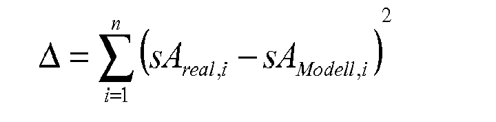
- a difference between the observed build-up sound path sA real and the calculated build-up sound path sA model is calculated, and a characteristic value is calculated from such a deviation.
- the method steps 26, 28, 30, 32 and 34 of the flow diagram 24 can be repeated, wherein the values for the damping constant kA, the spring stiffness cA and the body mass mA determined in the model parameterization 34 are respectively used as starting values.
- a vibration model is constructed in which the parameters for the body mass mA, the damping constant kA and the spring stiffness cA are kept variable, in which the parameterization of the vibration model is carried out in an iterative process, and in which the damping parameter for the vibration system can be calculated by means of the specific parameters.
- those parameters are searched for that best simulate the vibration curve.
- the motor vehicle is first in a vertical vibration by means of a defined excitation sR real offset, for example.
- a differential equation system describing the vibration of the vibration damper is set up at the detection timings. From this, the unknown quantities decay constant and natural angular frequency can be determined by means of mathematical methods which are known to the person skilled in the art and need not be explained here in detail, and finally the structural damping dimension of the vibration damper can be determined therefrom.
- the unknown quantities decay constant and natural angular frequency can be determined on the basis of a parameter estimation method known to the person skilled in the art and not to be explained here.
- the optimum solution for the decay constant and natural angular frequency parameters is determined so that the differential equation system is satisfied for each wheel and body motion measurement, as shown in the following equation.
- ⁇ i 1 n s ⁇ ⁇ A i + 2 ⁇ ⁇ ⁇ s ⁇ ⁇ A i - s ⁇ ⁇ R i + ⁇ 2 0 ⁇ sA i - sR i 2 ⁇ 0
- the attenuation amount can be determined based on the decay constant and the natural angular frequency according to the above formula.
- the inventive method for testing a vibration damper of a motor vehicle when installed can also be extended to a single-track model, in which the wheels of the front and rear axle are considered simultaneously, or to a four-wheel vehicle model.
- FIG. 4 shows a schematic representation of a four-wheel vehicle model 36th
- the four-wheel vehicle model 36 is composed of a front left damper vibration model 38, a front right damper vibration model 40, a rear left damper vibration model 42, and a rear right damper vibration model 44, respectivelyiserimposedmasse is no longer considered as a point mass, but as a mass disk, as in FIG. 4 is shown schematically. This results in two additional degrees of freedom ⁇ Axx and ⁇ Ayy for the consideration of the vertical movement.
- the four-wheel vehicle model leads to several differential equations. These include the wheel movements for all four wheels. For the structure there is then a total of one stroke movement and a pitch and roll oscillation. The lifting movement is linked to the vehicle mass. The pitch and roll oscillation is linked to the moments of inertia ⁇ Axx and ⁇ Ayy. The pitch and roll vibrations of the structure can be measured by image processing.
- the parameters for all four wheels are then optimized together, so that the simulated movement corresponds as well as possible to the real measured movement.
- the VL, VR, HL and HR are the corresponding measurements of the vehicle body at the positions Front Left, Front Right, Rear Left and Rear Right.
- the procedure for parameter determination corresponds to the flowchart 24 according to FIG. 3 wherein the block with the simulation model 30 then the four-wheel vehicle model according to FIG. 4 includes.
- the four vibration damper of the test vehicle 4 are checked in the installed state by determining the damping amounts for all wheels together for each vibration damper according to the inventive method of the type described above, and wherein the lifting, pitching and rolling movements of the Body dimensions are taken into account.
- the pitching or pitching and roll behavior of the vehicle can be assessed.
- a parameter identification it is then possible to compare both the degree of damping on the left and right-hand side of the axle as well as the values of the front axle and those of the rear axle.
- the differential equation of the system with the inertia parameters mA, ⁇ Axx and ⁇ Ayy describe a lifting, pitching and rolling motion of the body of the machine.
- FIG. 5 11 shows a first waveform diagram 46, a second waveform diagram 48, and a third waveform diagram 50.
- the course of the wheel movement sR is shown for three different damping coefficients, and correspondingly, the course of the body movement sA for these three damping coefficients is visualized in the third waveform.
- the vehicle longitudinal speed must be adjusted so that the vehicle response is optimal.
- the sleeper shape, the vehicle speed and the bodywork natural frequency the vehicle movement varies.
Abstract
Description
Die Erfindung betrifft ein Verfahren zum Prüfen eines Schwingungsdämpfers eines Kraftfahrzeugs im eingebauten Zustand, sowie ein Schwingungsdämpfer-Prüfsystem für ein Kraftfahrzeug.The invention relates to a method for testing a vibration damper of a motor vehicle in the installed state, as well as a vibration damper test system for a motor vehicle.
Gängige Schwingungsdämpfer umfassen eine Feder, sowie ein Dämpfungsglied, und sie dienen sowohl dazu, die Fahrsicherheit eines Kraftfahrzeugs zu gewährleisten, als auch dazu, den Fahrkomfort zu optimieren. Die Fahrsicherheit wird stark durch die Bodenhaftung der Reifen beeinflusst. Schwingungen der Radmassen werden daher durch starke Dämpfung häufig minimiert. Andererseits erfordert ein zufriedenstellender Fahrkomfort eine eher schwache Dämpfung. Bei der Auslegung von Schwingungsdämpfern ist daher ein Kompromiss zwischen harter Sicherheitsdämpfung und weicher Komfortdämpfung anzustreben.Common vibration dampers include a spring, as well as an attenuator, and they serve both to ensure the driving safety of a motor vehicle, as well as to optimize the ride comfort. Driving safety is strongly influenced by the grip of the tires. Vibrations of the wheel masses are therefore often minimized by strong damping. On the other hand, satisfactory ride comfort requires rather weak damping. In the design of vibration dampers, therefore, a compromise between hard safety damping and soft comfort damping is desirable.
Ein im Kraftfahrzeug eingebauter Schwingungsdämpfer verschleißt im Laufe des Fahrbetriebs und ändert sein Schwingungsverhalten sowie seine Dämpfercharakteristik, sodass nach einiger Zeit häufig ein sicherheitskritischer Zustand erreicht wird.An integrated in the motor vehicle vibration damper wears in the course of driving and changes its vibration behavior and its damper characteristics, so that after some time often a safety-critical state is reached.
Zur Überprüfung der Leistungsfähigkeit von Schwingungsdämpfern können diese ausgebaut und auf einem separaten Prüfstand vermessen werden. Dieses Prüfverfahren liefert zwar genaue Prüfergebnisse, ist jedoch aufgrund des Demontageaufwands aus Zeit- und Kostengründen nicht praktikabel und wird daher kaum eingesetzt.To test the performance of vibration dampers, these can be removed and measured on a separate test bench. Although this test method provides accurate test results, but is due to the dismantling effort for time and cost reasons impractical and is therefore hardly used.
Aus der
Hierfür sind aufwändige Prüfstandsaktuatoriken notwendig, die das Kraftfahrzeug in Schwingung versetzen. Des Weiteren hat sich gezeigt, dass die Reproduzierbarkeit der Messungen nicht immer gewährleistet ist, und dass die Messwerte für den Schwingungsdämpfer die Dämpfercharakteristik nur unzufriedenstellend beschreiben.For this purpose, complex Prüfstandsaktuatoriken necessary to set the vehicle in vibration. Furthermore, it has been shown that the reproducibility of the measurements is not always guaranteed, and that the measured values for the vibration damper only unsatisfactorily describe the damper characteristic.
Es ist daher Aufgabe der vorliegenden Erfindung, ein Verfahren sowie ein System zum Prüfen eines Schwingungsdämpfers eines Kraftfahrzeugs im eingebauten Zustand anzugeben, mit denen der eingebaute Schwingungsdämpfer zeit-und kostengünstig überprüft und bewertet werden können und mit denen schadhafte Schwingungsdämpfer zuverlässig identifiziert werden können.It is therefore an object of the present invention to provide a method and a system for testing a vibration damper of a motor vehicle in the installed state, with which the built-in vibration damper time and cost can be checked and evaluated and with which defective vibration damper can be reliably identified.
Diese Aufgabe wird durch den Gegenstand der unabhängigen Patentansprüche gelöst, vorteilhafte Weiterbildungen ergeben sich aus den abhängigen Ansprüchen.This object is achieved by the subject matter of the independent claims, advantageous developments emerge from the dependent claims.
Beide in den nebengeordneten Verfahrensansprüchen angegebenen Verfahren zum Prüfen eines Schwingungsdämpfers eines Kraftfahrzeugs im eingebauten Zustand gehen für die Modell-gestützte Auswertung von einer Betrachtung der Fahrzeugschwingung bei einer beliebigen Unebenheitsanregung als Einmassenschwinger aus.Both specified in the independent method claims method for testing a vibration damper of a motor vehicle in the installed state go for the model-based evaluation of a consideration of the vehicle vibration in any unevenness excitation as a single-mass oscillator.
Mittels des erfindungsgemäßen Verfahrens zum Prüfen einer Feder sowie einem Dämpfungsglied enthaltenden Schwingungsdämpfers kann der Zustand des eingebauten Schwingungsdämpfers getrennt bewertet werden, und die relevanten Parameter Dämpfungskonstante, Federsteifigkeit, Aufbaumasse und Dämpfungsmaß können hinreichend genau bestimmt werden. Schadhafte Dämpfer können somit zuverlässig identifiziert werden.By means of the method according to the invention for testing a spring and a vibration damper containing an attenuator, the state of the built-in vibration damper can be evaluated separately, and the relevant parameters damping constant, spring stiffness, body mass and damping measure can be determined with sufficient accuracy. Defective dampers can thus be reliably identified.
Erfindungsgemäß erfolgt die Erfassung der Bewegung von Rad und Karosserie mittels optischer Messtechnik, und das Kraftfahrzeug braucht nur mittels einer definierten, insbesondere einmaligen Anregung in eine vertikale Schwingung versetzt werden.According to the invention, the movement of the wheel and the body is detected by means of optical measuring technology, and the motor vehicle only needs to be set into a vertical oscillation by means of a defined, in particular single excitation.
Das erfindungsgemäße Verfahren mit der optischen Erfassung der Position des Rads und der Karosserie zu mehreren Erfassungszeitpunkten während der Schwingung ist grundsätzlich für eine beliebige Schwingungsanregung geeignet. Die Anregung kann mit möglichst geringem Aufwand durch die Überfahrt einer oder mehrerer Bodenschwellen bzw. Schwellen oder auf konventionellen Schwingungsdämpfer-Plattenprüfständen, bspw. durch vertikales Bewegen der Radauflage, auf welcher das Kraftfahrzeug steht, um eine bestimmte Strecke, erfolgen.The inventive method with the optical detection of the position of the wheel and the body at several detection times during the vibration is basically suitable for any vibration excitation. The excitation can be done with the least possible effort by the passage of one or more thresholds or thresholds or on conventional vibration damper Plattenprüfständen, eg. By vertical movement of the wheel, on which the motor vehicle is to a certain distance done.
Falls das Versetzen des Fahrzeugs in eine vertikale Schwingung durch Überfahren einer Schwelle erfolgt, kann die Rad- und Karosseriebewegung während der Fahrt über diese Schwelle gemessen werden. Der Begriff Schwelle wird dabei erfindungsgemäß als Oberbegriff für alle Anregungseinrichtungen erfolgt, die von einem Kraftfahrzeug überfahren werden und das Rad dabei temporär vertikal versetzen. Beliebige Hindernisse, bspw. Stufen und dergleichen, sind dabei erfindungsgemäß als Schwelle zu verstehen. Durch die Verwendung einer Schwelle zur Schwingungsanregung entfällt somit erfindungsgemäß eine aufwändige Prüfstandsaktuatorik, um das Kraftfahrzeug in Schwingung zu versetzen, und die notwendige Bewegungsenergie wird hierbei von dem Kraftfahrzeug selbst generiert.If the vehicle is put into a vertical oscillation by crossing a threshold, the wheel and body movement can be measured while driving above this threshold. The term threshold is in this case according to the invention as a generic term for all excitation devices that are run over by a motor vehicle and temporarily put the wheel vertically. Any obstacles, for example steps and the like, are to be understood according to the invention as a threshold. The use of a threshold for vibration excitation thus eliminates a complex Prüfstandsaktuatorik invention to put the vehicle in vibration, and the necessary kinetic energy is generated here by the motor vehicle itself.
Erfindungsgemäß erfolgt die Bewertung des Schwingungsdämpfers anhand einer Modell-basierten Auswertung der gemessenen Rad- und Karosseriebewegung unter Verwendung von Differenzialgleichungen zur Bestimmung der Parameter für die Dämpfungskonstante bzw. Aufbaudämpfungskonstante, für die Federsteifigkeit bzw. Aufbaufedersteifigkeit und für die Aufbaumasse, und aus diesen Parametern kann das Dämpfungsmaß berechnet werden. Das Dämpfungsmaß, das auch als Dämpfungsgrad oder Lehr'sche Dämpfung bezeichnet wird, setzt die Größe der Achsdämpfung in Zusammenhang zu der Aufbaumasse und der Federsteifigkeit. Das Dämpfungsmaß ist eine dimensionslose Größe und ermöglicht die Beurteilung der in einem Schwingungssystem enthaltenen Dämpfung unter Berücksichtigung der relevanten Schwingungsparameter. Das Dämpfungsmaß ist geeignet, Schwingungsdämpfer verschiedener Fahrzeuge objektiv miteinander zu vergleichen und auf Einhaltung von Grenzwerten für die Fahrsicherheit zu überprüfen.According to the evaluation of the vibration damper based on a model-based evaluation of the measured wheel and body movement using differential equations to determine the parameters for the damping constant or structural damping constant, for the spring stiffness or Aufbaufedersteifigkeit and for the body mass, and from these parameters can Damping be calculated. The damping measure, the Also referred to as degree of damping or Lehr'sche damping, the size of the axle damping is related to the body mass and the spring stiffness. The damping measure is a dimensionless variable and allows the assessment of the damping contained in a vibration system taking into account the relevant vibration parameters. The degree of damping is suitable to objectively compare vibration dampers of different vehicles and to check compliance with limits for driving safety.
Im Unterschied zu bisherigen Prüfverfahren spielt bei der erfindungsgemäßen Schwingungsdämpferprüfung die Messgröße Radaufstandskraft keine Rolle, und dadurch kann eine Vereinfachung der Prüfanordnung und ein Wegfall von aufwändigen Prüfstandsaktuatoriken und Sensoren zur Messung von Radaufstandskräften erreicht werden.In contrast to previous test methods, the measured variable wheel contact force plays no role in the vibration damper test according to the invention, and as a result a simplification of the test arrangement and elimination of complex test bench actuators and sensors for measuring wheel contact forces can be achieved.
Des Weiteren wird erfindungsgemäß die Relativbewegung zwischen Kraftfahrzeugrad und Karosserie betrachtet, wodurch der störende Einfluss des Reifens auf das Prüfergebnis eliminiert wird. Damit werden eine Vereinfachung des Schwingungsmodells, bei dem ein sogenannter Einmassenschwinger anstelle eines Zweimassenschwingers betrachtet wird, und zugleich eine deutliche Verbesserung der Bewertung des Zustands der Schwingungsdämpfer erreicht.Furthermore, the relative movement between the motor vehicle wheel and the body is considered according to the invention, whereby the disturbing influence of the tire on the test result is eliminated. Thus, a simplification of the vibration model, which considers a so-called single-mass oscillator instead of a two-mass oscillator, and at the same time a significant improvement in the evaluation of the state of the vibration damper is achieved.
Erfindungsgemäß werden aus den gemessenen Bilddaten anschließend die Bewegungen von Karosserie bzw. Fahrzeugaufbau und dem Kraftfahrzeuggrad basierend auf mehreren Erfassungszeitpunkten ermittelt. Diese Bewegungsgrößen dienen in ihrer Zeit- und Wegabhängigkeit als Grundlage für die Bewertung der Schwingungsdämpfer.According to the invention, the movements of the body or vehicle body and the motor vehicle degree are then determined based on a plurality of detection times from the measured image data. These motion variables serve in their time and path dependence as a basis for the evaluation of the vibration damper.
Mit dem erfindungsgemäßen Verfahren lässt sich auf einfache Weise der Zustand der Schwingungsdämpfer im eingebauten Zustand bewerten. Eine getrennte Bewertung der vier Schwingungsdämpfer ist möglich, sodass Unterschiede direkt erkannt werden. Aufgrund des einfachen Messverfahrens und der schnellen Abarbeitung des Auswertealgorithmus in der Rechnereinheit des Messsystems liegen die Ergebnisse direkt nach der Durchführung der Messung vor, was einen großen Vorteil im Vergleich zu den bestehenden Prüfansätzen darstellt.With the method according to the invention can be evaluated in a simple manner, the state of the vibration damper in the installed state. A separate evaluation of the four vibration dampers is possible, so that differences are detected directly. Due to the simple measuring method and the fast processing of the evaluation algorithm in the computer unit of the measuring system, the results are available directly after the measurement, which represents a major advantage compared to the existing test approaches.
Die Erfindung betrifft auch ein Verfahren zum Prüfen der Schwingungsdämpfer wenigstens einer Achse eines Kraftfahrzeugs im eingebauten Zustand, bei dem das Verfahren zum Prüfen eines Schwingungsdämpfers eines Kraftfahrzeugs im eingebauten Zustand gemäß der beschriebenen Art nacheinander für die Räder der betreffenden Achse durchgeführt wird, um die Dämpfungsmaße oder die Dämpfung der Achse zu bestimmen, und bei dem die Hub-, Nick- und Wankbewegungen der Aufbaumaße berücksichtigt werden. Dadurch lässt sich das erfindungsgemäße Verfahren zum Prüfen eines Schwingungsdämpfers eines Kraftfahrzeugs im eingebauten Zustand auch auf ein Einspurmodell oder ein Vierrad-Fahrzeugmodell erweitern.The invention also relates to a method for testing the vibration damper of at least one axle of a motor vehicle in the installed state, in which the method for testing a vibration damper of a motor vehicle in the installed state according to the described type is carried out successively for the wheels of the relevant axis to the attenuation measurements or To determine the damping of the axis, and in which the lifting, pitching and rolling movements of the mounting dimensions are taken into account. As a result, the inventive method for testing a vibration damper of a motor vehicle in the installed state can also be extended to a single-track model or a four-wheel vehicle model.
Die Erfindung betrifft des Weiteren ein Schwingungsdämpfer-Prüfsystem für ein Kraftfahrzeug mit wenigstens einem Messkopf zum optischen Erfassen der Position eines Rads und der Karosserie des Kraftfahrzeugs zu mehreren Erfassungszeitpunkten, eine Anregungseinrichtung zum Versetzen des Kraftfahrzeugs in eine vertikale Schwingung, insbesondere eine Schwelle zum Überfahren durch das Kraftfahrzeug sowie eine Datenverarbeitungseinheit. Diese ist mit dem Messkopf verbunden und eingerichtet, um Messdaten von dem betreffenden Messkopf zu empfangen und um ein Verfahren zum Prüfen eines Schwingungsdämpfers eines Kraftfahrzeugs im eingebauten Zustand der oben beschriebenen Art durchzuführen.The invention further relates to a vibration damper test system for a motor vehicle having at least one measuring head for optically detecting the position of a wheel and the body of the motor vehicle at a plurality of detection times, an excitation device for moving the motor vehicle into a vertical oscillation, in particular a threshold for driving over it Motor vehicle and a data processing unit. This is connected to the measuring head and arranged to receive measurement data from the respective measuring head and to perform a method for testing a vibration damper of a motor vehicle in the installed state of the type described above.
Die Erfindung ist nachfolgend anhand von Ausführungsbeispielen mit Bezug auf die beiliegenden Figuren näher erläutert.
-
Figur 1 -
Figur 2 zeigt eine Prinzipskizze eines Schwingungsmodells; -
Figur 3 zeigt ein Ablaufdiagramm eines ersten erfindungsgemäßen Verfahrens zum Prüfen eines Schwingungsdämpfers des Versuchsfahrzeugs ausFigur 1 -
Figur 4 -
Figur 5
-
FIG. 1 shows an inventive measuring system and a test vehicle whose vibration damper to be checked according to the invention; -
FIG. 2 shows a schematic diagram of a vibration model; -
FIG. 3 shows a flowchart of a first method according to the invention for testing a vibration damper of the test vehicleFIG. 1 ; -
FIG. 4 shows a schematic representation of a four-wheel vehicle model; and -
FIG. 5 shows a first, a second and a third waveform diagram.
Das Messsystem 2 umfasst eine längliche Schwelle von definierter Höhe, deren Haupterstreckungsrichtung im Wesentlichen rechtwinklig zu der Bewegungsrichtung 6 des Versuchsfahrzeugs 4 angeordnet ist. Die Breite der Schwelle 8 entspricht wenigstens der Breite des Versuchsfahrzeugs 4, sodass beim Überfahren der Schwelle 8 in Bewegungsrichtung 6 durch das Versuchsfahrzeug 4 jeweils beide Räder der gleichen Achse durch die Schwelle 8 eine definierte Anregung erfahren und dadurch in eine vertikale Schwingung versetzt werden.The measuring system 2 comprises an elongated threshold of defined height, whose main extension direction is arranged substantially perpendicular to the direction of
Seitlich neben der Schwelle 8, entweder auf Höhe der Schwelle 8 oder kurz danach, sind ein linker Messkopf 10 und ein rechter Messkopf 12 angeordnet, die jeweils nach innen gerichtete Messkameras, bspw. CCD-Sensoren, umfassen, die in geeigneter Höhe angebracht und in der Lage sind, die Position des Rads und der Karosserie des Kraftfahrzeugs, insbesondere bestimmter Merkmale auf dem Rad, bspw. das Felgenhorn oder bestimmte Bohrungen, und auf der Karosserie, bspw. den Rand des Kotflügels, optisch zu erfassen.On the side of the
Das Schwingungsmodell 14 ist ein Weg-angeregtes Einmassenschwingsystem (EMS), mit dem sich die Schwingung zwischen dem Fahrzeugaufbau und dem Kraftfahrzeugrad beschreiben lässt. Das Schwingungsmodell 14 stellt die Betrachtung eines Viertelfahrzeugs dar, d. h., eine Achsseite mit der anteiligen Aufbaumasse mA.The
Die Kraftfahrzeugmasse bzw. Aufbaumasse mA ist mit dem Bezugszeichen 20 gekennzeichnet und schematisch als Rechteck dargestellt. Die Radachse 22 bzw. die Radaufhängung ist mit dem Bezugszeichen 22 gekennzeichnet. Der Schwingungsdämpfer wird von der Feder 16 mit der Federsteifigkeit cA und dem parallelen Dämpfungsglied 18 mit dem Dämpfungsfaktor kA gebildet, und die Aufbaumasse 20 ist durch diesen Schwingungsdämpfer auf der Radachse 22 gelagert.The vehicle mass or body mass mA is identified by the
Die Richtung der Bewegung des Kraftfahrzeugrads bzw. der Radbewegung sR ist mit einem nach oben gerichteten Pfeil dargestellt, und die Richtung der Bewegung des Kraftfahrzeugaufbaus bzw. der Aufbaubewegung sA ist ebenfalls mit einem nach oben gerichteten Pfeil dargestellt.The direction of movement of the vehicle wheel or the wheel movement sR is shown with an upward arrow, and the direction of movement of the vehicle body or the body movement sA is also shown with an upward arrow.
Das Messsystem 2 verfügt des Weiteren noch über eine Datenverarbeitungseinheit, die die Messwerte von den Messkameras der Messköpfe 10 und 12 erhält und die eingerichtet ist, um das erfindungsgemäße Verfahren durchzuführen.The measuring system 2 furthermore has a data processing unit which receives the measured values from the measuring cameras of the measuring heads 10 and 12 and which is set up to carry out the method according to the invention.
Das Messsystem 2 kann über die Möglichkeit einer Dateneingabe verfügen, mittels derer Daten für das zu prüfende Fahrzeug entweder manuell über eine angeschlossene Tastatur oder über eine Datenkopplung zu einem anderen Computer oder durch Einlesen von einem Speichermedium eingegeben werden können.The measuring system 2 can have the option of data input, by means of which data for the vehicle to be tested can be entered either manually via a connected keyboard or via a data link to another computer or by reading from a storage medium.
Die Aufbaumasse 20 wird aufgrund der Bewegung des Kraftfahrzeugrads und die Übertragung durch den Schwingungsdämpfer zum Schwingen angeregt.The
Die Schwingung des in 
Diese Differenzialgleichung ist eine homogene Gleichung, die Größen mA, kA und cA können jeweils mit einem gemeinsamen Faktor multipliziert werden, ohne dass sich die Lösung der Differenzialgleichung ändert.This differential equation is a homogeneous equation, the quantities mA, kA and cA can each be multiplied by a common factor without the solution of the differential equation changing.
Während der Bestimmung der Parameter muss eine der drei Größen mA, kA und cA bekannt sein und kann in der Optimierung nicht bestimmt werden. Eine gemeinsame Bestimmung aller drei Parameter ist nicht möglich.During the determination of the parameters, one of the three quantities mA, kA and cA must be known and can not be determined in the optimization. A common determination of all three parameters is not possible.
In der Praxis wird die Fahrzeugmasse mA als bekannt angenommen und es werden nur der Dämpfungsfaktor kA und die Federsteifigkeit cA in der Optimierung bestimmt.In practice, the vehicle mass mA is assumed to be known and only the damping factor kA and the spring stiffness cA are determined in the optimization.
Wird diese Differenzialgleichung durch die Aufbaumasse mA geteilt, so ergibt sich folgende Formulierung der Differenzialgleichung: 
Dabei stellen δ die Abklingkonstante 


Die Eigenkreisfrequenz ist somit durch die Federsteifigkeit cA und durch die Aufbaumasse mA definiert, und sie wird nicht durch die Dämpfung beeinflusst. Üblicherweise liegt die Eigenkreisfrequenz knapp unter 2 Hz.The natural angular frequency is thus defined by the spring stiffness cA and the body mass mA, and it is not affected by the damping. Usually, the natural angular frequency is just below 2 Hz.
Zu Beginn des Verfahrens werden Startwerte der Dämpfungskonstanten kA, der Federsteifigkeit cA und der Aufbaumasse mA für das zu betrachtende Rad des Kraftfahrzeugs bestimmt. Zusätzlich können für diese Parameter noch Grenzwerte definiert werden. Solche Start- und Grenzwerte können im einfachsten Fall aus Erfahrungswerten abgeleitet werden, zur Verbesserung aus verfügbaren Fahrzeugdaten abgeschätzt werden oder mit vorangegangenen Messungen, wie bspw. der Fahrzeugmasse oder der Radlast, genauer bestimmt werden.At the beginning of the method, starting values of the damping constant kA, the spring stiffness cA and the body mass mA are determined for the wheel of the motor vehicle to be considered. In addition, limit values can be defined for these parameters. In the simplest case, such start and limit values can be derived from empirical values, estimated for improvement from available vehicle data, or determined more accurately with previous measurements, such as, for example, the vehicle mass or the wheel load.
Im ersten Verfahrensschritt erfolgt eine Schwingungsanregung 26 durch Überfahren der Schwelle 8 mit dem jeweiligen Rad des Versuchsfahrzeugs 4. Durch die definierte Anregung sE wird das Versuchsfahrzeug 4 in vertikale Schwingung versetzt, die von dem Dämpfungsglied 18 des jeweiligen Kraftfahrzeugrads gedämpft wird.In the first method step, an
Im zweiten Verfahrensschritt erfolgt die Messung 28 durch die Messköpfe 10 und 12. Dabei werden das zu betrachtende Rad und die benachbarte Karosserie des Versuchsfahrzeugs 4 durch die Kameras des jeweils direkt gegenüberliegenden Messkopfs 10 und 12 betrachtet, und die Positionen des Rads und der Karosserie werden während der Schwingung optisch erfasst.In the second method step, the
Im nächsten Verfahrensschritt wird durch das Simulationsmodell 30 der theoretische Aufbauschwingweg sAModell berechnet, wobei die definierte Anregung sRreal, die Fahrzeugmasse für das betreffende Kraftfahrzeugrad mA, die Dämpfungskonstante kA und die Federsteifigkeit cA als Parameter verwendet werden.In the next step of the method, the
Die Fahrzeugbewegung (sRreal, sAreal) wird mittels dem zu betrachtenden Kraftfahrzeugrad gegenüberliegenden Messkopf 10 oder 12 gemessen.The vehicle movement (sR real , sA real ) is measured by means of the opposite of the vehicle wheel to be considered measuring
Als Ergebnis des Simulationsmodells 30 ergibt sich der berechnete Aufbauschwingweg sAModell als Modellausgangsgröße. Parallel dazu wird der tatsächliche Aufbauschwingweg sAreal beobachtet und zu den verschiedenen Erfassungszeitpunkten mit dem berechneten Aufbauschwingweg sAModell verglichen. Insbesondere wird im Verfahrensschritt 32 eine Differenz zwischen dem beobachteten Aufbauschwingweg sAreal und dem berechneten Aufbauschwingweg sAModell berechnet, und aus einer derartigen Abweichung wird ein Kennwert berechnet.As a result of the
Insbesondere kann diese Abweichung anhand einer Fehlerfunktion beschrieben werden, bspw. durch die wie folgt definierte Fehlerfunktion, welche die Summe der Fehlerquadrate zwischen Modell und Messungen bildet: 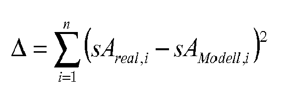
Diese nicht lineare Fehlerfunktion mit mehreren Variablen kann durch Verwendung von dem Fachmann bekannten mathematischen Verfahren minimiert werden. Als Ergebnis erhält man Messwerte für die Dämpfungskonstante kA, für die Federsteifigkeit cA und für die Aufbaumasse mA, und daraus lässt sich das Dämpfungsmaß des Schwingungsdämpfers nach der folgenden Formel bestimmen: 
Im Verfahrensschritt der Modellparametrisierung 34 werden demnach diejenigen Parameter für die Dämpfungskonstante kA, die Federsteifigkeit cA und die Aufbaumasse mA berechnet, die eine optimale Überdeckung zwischen realer und Modell-basierter Aufbaubewegung darstellen.In the method step of the
Die Verfahrensschritte 26, 28, 30, 32 und 34 des Ablaufdiagramms 24 können wiederholt werden, wobei jeweils die in der Modellparametrisierung 34 bestimmten Werte für die Dämpfungskonstante kA, die Federsteifigkeit cA und die Aufbaumasse mA als Startwerte verwendet werden.The method steps 26, 28, 30, 32 and 34 of the flow diagram 24 can be repeated, wherein the values for the damping constant kA, the spring stiffness cA and the body mass mA determined in the
Bei dem in
Gemäß einem zweiten, nicht in
Insbesondere können die unbekannten Größen Abklingkonstante und Eigenkreisfrequenz anhand eines dem Fachmann bekannten und hier nicht näher zu erläuternden Parameterschätzverfahrens ermittelt werden. Mittels dieses Parameterschätzverfahrens wird die optimale Lösung für die Parameter Abklingkonstante und Eigenkreisfrequenz bestimmt, sodass das Differenzialgleichungssystem für jeden Messwert der Rad- und Aufbaubewegung erfüllt ist, wie es in der folgenden Gleichung dargestellt ist. 
Das Dämpfungsmaß kann basierend auf der Abklingkonstante und der Eigenkreisfrequenz nach der oben genannten Formel bestimmt werden.The attenuation amount can be determined based on the decay constant and the natural angular frequency according to the above formula.
Das erfindungsgemäße Verfahren zum Prüfen eines Schwingungsdämpfers eines Kraftfahrzeugs im eingebauten Zustand lässt sich auch auf ein Einspurmodell, bei dem die Räder der Vorder- und Hinterradachse gleichzeitig betrachtet werden, oder auf ein Vierrad-Fahrzeugmodell erweitern.The inventive method for testing a vibration damper of a motor vehicle when installed can also be extended to a single-track model, in which the wheels of the front and rear axle are considered simultaneously, or to a four-wheel vehicle model.
Das Vierrad-Fahrzeugmodell 36 setzt sich aus einem Schwingungsmodell 38 für den vorderen linken Schwingungsdämpfer, aus einem Schwingungsmodell 40 für den vorderen rechten Schwingungsdämpfer, aus einem Schwingungsmodell 42 für den hinteren linken Schwingungsdämpfer und aus einem Schwingungsmodell 44 für den hinteren rechten Schwingungsdämpfer zusammen, wobei die Fahrzeugaufbaumasse nicht mehr als Punktmasse, sondern als massebehaftete Scheibe betrachtet wird, wie dies in
Das Vierrad-Fahrzeugmodell führt zu mehreren Differentialgleichungen. Diese beinhalten die Radbewegungen für alle vier Räder. Für den Aufbau gibt es dann insgesamt eine Hubbewegung sowie eine Nick- und Wankschwingung. Die Hubbewegung ist mit der Fahrzeugmasse verknüpft. Die Nick- und Wankschwingung ist mit den Trägheitsmomenten θAxx und θAyy verknüpft. Die Nick- und Wankschwingungen des Aufbaus können über die Bildverarbeitung gemessen werden.The four-wheel vehicle model leads to several differential equations. These include the wheel movements for all four wheels. For the structure there is then a total of one stroke movement and a pitch and roll oscillation. The lifting movement is linked to the vehicle mass. The pitch and roll oscillation is linked to the moments of inertia θAxx and θAyy. The pitch and roll vibrations of the structure can be measured by image processing.
Bei der Parameteroptimierung werden dann die Parameter für alle vier Räder gemeinsam optimiert, so dass die simulierte Bewegung möglichst gut der real gemessenen Bewegung entspricht. Somit gilt: 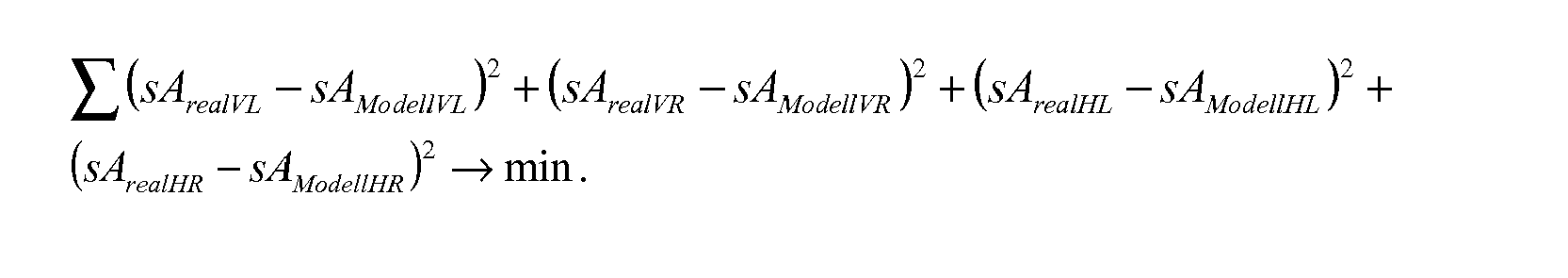
Dabei sind VL, VR, HL und HR die entsprechenden Messungen des Fahrzeugaufbaus an den Positionen Vorne Links, Vorne Rechts, Hinten Links und Hinten Rechts.In parameter optimization, the parameters for all four wheels are then optimized together, so that the simulated movement corresponds as well as possible to the real measured movement. Thus:
The VL, VR, HL and HR are the corresponding measurements of the vehicle body at the positions Front Left, Front Right, Rear Left and Rear Right.
In der Veröffentlichung der RWTH Aachen: Institut für Kraftfahrwesen, Wallentowitz, Henning: Vertikal-/Querdynamik von Kraftfahrzeugen, 7. Auflage 2005, ISNB 3-925194-35-5 ist das Einspurmodell und das Vierrad-Fahrzeugmodell im Einzelnen erläutert, und dies ist dem Fachmann bekannt.In the publication of RWTH Aachen: Institute of Automotive Engineering, Wallentowitz, Henning: Vertical / transverse dynamics of motor vehicles, 7th edition 2005, ISNB 3-925194-35-5, the single-track model and the four-wheel vehicle model is explained in detail, and this is known to the skilled person.
Das Vorgehen zur Parameterbestimmung entspricht dem Ablaufdiagramm 24 gemäß
Gemäß dem Vierrad-Fahrzeugmodell 36 werden die vier Schwingungsdämpfer des Versuchsfahrzeugs 4 im eingebauten Zustand überprüft, indem für jeden Schwingungsdämpfer nach dem erfindungsgemäßen Verfahren der oben beschriebenen Art die Dämpfungsmaße für alle Räder gemeinsam bestimmt werden, und wobei die Hub-, Nick- und Wankbewegungen der Aufbaumasse berücksichtigt werden.According to the four-
Somit lässt sich das Nick- bzw. das Nick- und Wankverhalten des Fahrzeugs beurteilen. Anhand einer Parameteridentifikation kann dann sowohl das Dämpfungsmaß auf der linken und rechten Achsseite miteinander verglichen werden, als auch die Werte der Vorderachse mit denen der Hinterachse. Die Differenzialgleichung des Systems mit den Trägheitsparametern mA, θAxx und θAyy beschreiben eine Hub-, Nick- und Wankbewegung der Aufbaumasse.Thus, the pitching or pitching and roll behavior of the vehicle can be assessed. On the basis of a parameter identification, it is then possible to compare both the degree of damping on the left and right-hand side of the axle as well as the values of the front axle and those of the rear axle. The differential equation of the system with the inertia parameters mA, θAxx and θAyy describe a lifting, pitching and rolling motion of the body of the machine.
Im ersten Schwingungsverlaufsdiagramm 46 sind für ein Dämpfungsmaß von ϑ = 0,3 drei Kurven im Zeitverlauf dargestellt, nämlich als durchgezogene Linie der Verlauf der Schwingungsanregung, als gleichmäßig unterbrochene Linie der Verlauf der Radbewegung sR und als weitere gestrichelte Linie der Verlauf der Aufbaubewegung sA. Dabei ist zu erkennen, dass im Zeitintervall zwischen Sekunde 5 und 5,5 die Schwingungsanregung bspw. durch Überfahrt der Schwelle 8 erfolgt, und dass die Aufbaubewegung sA der Radbewegung sR leicht hinterher hinkt und deutlich höhere Amplitudenwerte als diese aufweist. Zum Zeitpunkt t = 8 s ist die Schwingung beendet.In the first waveform diagram 46, three curves over time are shown for a damping amount of .theta. = 0.3, namely the waveform of the vibration excitation as a solid line, the course of the wheel movement sR as a uniformly broken line, and the course of the body movement sA as a further dashed line. It can be seen that in the time interval between the second 5 and 5.5, the vibration excitation, for example. By crossing the
In dem zweiten Schwingungsverlaufsdiagramm 48 ist der Verlauf der Radbewegung sR für drei verschiedene Dämpfungskoeffizienten dargestellt, und korrespondierend hierzu ist im dritten Schwingungsverlaufsdiagramm 50 der Verlauf der Aufbaubewegung sA für diese drei Dämpfungskoeffizienten visualisiert. Nach der definierten Anregung zwischen Sekunde 5 und 5,5 ist nur eine Schwingung mit geringer Amplitude zu beobachten, wobei bei der Aufbaubewegung sA eine Schwingung mit deutlich höherer Amplitude zu beobachten ist, die der Schwingung der Radbewegung sR leicht hinterher hinkt.In the second waveform diagram 48, the course of the wheel movement sR is shown for three different damping coefficients, and correspondingly, the course of the body movement sA for these three damping coefficients is visualized in the third waveform. After the defined excitation between the second 5 and 5.5, only one oscillation with low amplitude can be observed, during the body movement sA an oscillation with a clearly higher amplitude is observed, which lags slightly behind the oscillation of the wheel movement sR.
Bei geringerem Dämpfungskoeffizienten ergibt sich jeweils eine größere Amplitude. Bei der Schwellenüberfahrt muss die Fahrzeuglängsgeschwindigkeit angepasst werden, damit die Fahrzeugreaktion optimal ist. Abhängig von der Schwellenlänge, der Schwellenform, der Fahrgeschwindigkeit und der Aufbaueigenfrequenz variiert die Fahrzeugbewegung.With a lower damping coefficient results in each case a larger amplitude. During the threshold crossing, the vehicle longitudinal speed must be adjusted so that the vehicle response is optimal. Depending on the threshold length, the sleeper shape, the vehicle speed and the bodywork natural frequency, the vehicle movement varies.
Eine maximale Fahrzeugreaktion wird bei einer Anregungsfrequenz f im Bereich der Aufbaueigenfrequenz f0 erreicht. Mit sinkender Anregungsfrequenz nimmt die Amplitudenüberhöhung, nämlich das Verhältnis sAmax/sRmax schnell ab. Oberhalb der Eigenfrequenz liegt sie bis zu einem Frequenzverhältnis f/f0=3 oberhalb von
- 1. Um eine maximale Auflösung des Messsystems 2 und eine größtmögliche Fahrzeugreaktion zu erreichen, soll die Fahrzeugbewegung möglichst groß sein. Üblicherweise liegt die Aufbaueigenfrequenz eines Fahrzeugs bei 1
Hz bis 
Die Fahrgeschwindigkeit v liegtim Schrittgeschwindigkeitsbereich bei 1 bis 2 m/s. Die Schwellenlänge in Fahrtrichtung sollte für diese Geschwindigkeit etwa 250 mm betragen.
- 1. In order to achieve a maximum resolution of the measuring system 2 and a maximum vehicle response, the vehicle movement should be as large as possible. Normally, the build-up natural frequency of a vehicle is 1 Hz to 1.5 Hz. An excitation frequency f between 1 Hz and 3 Hz is advantageous. The relationship between excitation frequency f, driving speed v and wavelength I is given by the following equation:
The travel speed v is in the step speed range at 1 to 2 m / s. The threshold length in the direction of travel should be about 250 mm for this speed.
Claims (10)
Setzen von Startwerten der Dämpfungskonstante kA, der Federsteifigkeit cA und der Aufbaumasse mA für ein Rad eines Kraftfahrzeugs (4);
Versetzen des Kraftfahrzeugs (4) in eine vertikale Schwingung mittels einer definierten Anregung sRreal;
Bestimmen des theoretischen Aufbauschwingwegs sAModell;
Optisches Erfassen der Positionen des Rades und der Karosserie des Kraftfahrzeugs (4) zu mehreren Erfassungszeitpunkten während der Schwingung; Minimieren der aus den Abweichungen zwischen dem theoretischen Aufbauschwingweg sAModell und dem beobachteten Aufbauschwingweg sAreal an den Erfassungszeitpunkten gebildeten Fehlerfunktion und Bestimmen der Dämpfungskonstanten kA, der Federsteifigkeit cA und der Aufbaumasse mA daraus; und Bestimmen des Dämpfungsmaßes ϑ des Schwingungsdämpfers.Method for testing a vibration damper of a motor vehicle (4) when installed, comprising
Setting start values of the damping constant kA, the spring stiffness cA and the body mass mA for a wheel of a motor vehicle (4);
Displacing the motor vehicle (4) into a vertical oscillation by means of a defined excitation sR real ;
Determining the theoretical building swing path sA model ;
Optically detecting the positions of the wheel and the body of the motor vehicle (4) at a plurality of detection timings during the vibration; Minimizing the error function formed from the deviations between the theoretical build-up waveform sA model and the observed build-up sWave real at the acquisition times, and determining the damping constants kA, spring stiffness cA, and build-up mA mA therefrom; and determining the amount of damping θ of the vibration damper.
Versetzen des Kraftfahrzeugs (4) in eine vertikale Schwingung mittels einer definierten Anregung sRreal;
Optisches Erfassen der Positionen des Rades und der Karosserie des Kraftfahrzeugs (4) zu mehreren Erfassungszeitpunkten während der Schwingung; Aufstellen eines die Schwingung des Schwingungsdämpfers beschreibenden Differentialgleichungssystems zu den Erfassungszeitpunkten;
Ermitteln der unbekannten Größen: Abklingkonstante δ und Eigenkreisfrequenz ω0 in dem Differentialgleichungssystem; und
Bestimmen der Aufbaudämpfungsmaßes ϑ des Schwingungsdämpfers.Method for testing a vibration damper of a motor vehicle (4) when installed, comprising
Displacing the motor vehicle (4) into a vertical oscillation by means of a defined excitation sR real ;
Optically detecting the positions of the wheel and the body of the motor vehicle (4) at a plurality of detection timings during the vibration; Establishing a differential equation system describing the vibration of the vibration damper at the detection times;
Determine the unknown quantities: δ decay constant and natural angular frequency ω 0 in the system of differential equations; and
Determining the structural damping measure θ of the vibration damper.


wobei δ die Abklingkonstante


where δ is the decay constant

bei dem das Verfahren zum Prüfen eines Schwingungsdämpfers eines Kraftfahrzeugs (4) im eingebauten Zustand nach einem der vorgehenden Ansprüche für die Räder der betreffenden Achse durchgeführt wird, um die Dämpfungsmaße ϑ für die Räder der betreffenden Achse oder die Dämpfung der Achse zu bestimmen, und bei dem die Hub-, Nick- und Wankbewegungen der Aufbaumasse berücksichtigt werden.Method for testing the vibration dampers of at least one axle of a motor vehicle (4) when installed,
in which the method for testing a vibration damper of a motor vehicle (4) in the installed state according to one of the preceding claims for the wheels of the relevant axis is performed to determine the damping amounts θ for the wheels of that axle or the damping of the axle, and in which the lifting, pitching and rolling movements of the body are taken into account.
eine Anregungseinrichtung zum Versetzen des Kraftfahrzeugs in eine vertikale Schwingung, inbesondere eine Schwelle (8) zum Überfahren durch das Kraftfahrzeug (4); und
eine Datenverarbeitungseinheit, die eingerichtet ist, um Messdaten von dem Messkopf (10,12) zu empfangen und dum ein Verfahren nach einem der vorhergehenden Ansprüche durchzuführen.A vibration damper testing system (2) for a motor vehicle (4), comprising at least one measuring head (10, 12) for optically detecting the positions of a wheel and the body of the motor vehicle (4) at several detection times;
an excitation device for moving the motor vehicle into a vertical oscillation, in particular a threshold (8) for driving over by the motor vehicle (4); and
a data processing unit configured to receive measurement data from the measurement head (10, 12) and to perform a method according to any one of the preceding claims.
Applications Claiming Priority (1)
| Application Number | Priority Date | Filing Date | Title |
|---|---|---|---|
| DE102008002484A DE102008002484A1 (en) | 2008-06-17 | 2008-06-17 | Method for testing a vibration damper of a motor vehicle when installed and vibration damper test system for a motor vehicle |
Publications (3)
| Publication Number | Publication Date |
|---|---|
| EP2136195A2 true EP2136195A2 (en) | 2009-12-23 |
| EP2136195A3 EP2136195A3 (en) | 2016-08-17 |
| EP2136195B1 EP2136195B1 (en) | 2021-07-07 |
Family
ID=41066640
Family Applications (1)
| Application Number | Title | Priority Date | Filing Date |
|---|---|---|---|
| EP09161193.9A Active EP2136195B1 (en) | 2008-06-17 | 2009-05-27 | Method and device for testing an installed shock absorber of a motor vehicle |
Country Status (3)
| Country | Link |
|---|---|
| US (1) | US8452552B2 (en) |
| EP (1) | EP2136195B1 (en) |
| DE (1) | DE102008002484A1 (en) |
Cited By (4)
| Publication number | Priority date | Publication date | Assignee | Title |
|---|---|---|---|---|
| WO2015044277A1 (en) * | 2013-09-30 | 2015-04-02 | Hochschule für Technik und Wirtschaft Dresden | Arrangement and method for ascertaining chassis properties and other properties of a vehicle |
| EP3037801A1 (en) * | 2014-12-22 | 2016-06-29 | FSD Fahrzeugsystemdaten GmbH | Method and device for the determination of dynamic wheel contact force |
| DE102018113138A1 (en) * | 2018-06-01 | 2019-12-05 | Neimcke GmbH & Co. KG | Arrangement and method for detecting and / or evaluating vibrations |
| IT202100005003A1 (en) * | 2021-03-04 | 2022-09-04 | Derossi Massimo Srl | METHOD AND DEVICE FOR TESTING THE SUSPENSION OF A MOTOR VEHICLE |
Families Citing this family (22)
| Publication number | Priority date | Publication date | Assignee | Title |
|---|---|---|---|---|
| DE102010038905A1 (en) | 2010-08-04 | 2012-02-09 | Robert Bosch Gmbh | Method and device for determining wheel and body movements of a vehicle |
| BR112013006913B1 (en) * | 2010-09-24 | 2020-10-20 | Rassini Fresnos, S.A. De C.V. | workpiece damping measurement method |
| DE102011087594A1 (en) * | 2011-12-01 | 2013-06-06 | Bayerische Motoren Werke Aktiengesellschaft | Method for functional monitoring of vibration damper for wheel of passenger car, involves obtaining correct function and incorrect function of vibration damper, such that recognized incorrect function is provided in display |
| WO2013163175A1 (en) * | 2012-04-23 | 2013-10-31 | Rassini Frenos, S.A. De C.V. | Method and apparatus for measuring damping in a workpiece |
| JP6090336B2 (en) * | 2013-01-23 | 2017-03-08 | トヨタ自動車株式会社 | Vehicle vibration analysis method and vibration analysis apparatus |
| CN103115651B (en) * | 2013-02-26 | 2015-05-13 | 广东交通职业技术学院 | Method for detecting fuel consumption of vehicle in transient road-test standard state |
| WO2015182168A1 (en) * | 2014-05-28 | 2015-12-03 | 株式会社ショーワ | Method and system for inspecting damping force variable mechanism, and method for inspecting pressure damping device |
| AU2017354936A1 (en) * | 2016-11-03 | 2019-04-04 | Maluva Engineering Pty Ltd | Method and apparatus for measuring and logging the performance of a vehicle suspension system |
| CN106596145A (en) * | 2016-12-27 | 2017-04-26 | 重庆大学 | Motorcycle shock absorber testing and control system |
| CN107977497B (en) * | 2017-11-23 | 2020-05-15 | 吉林大学 | Parameter optimization method for vibration reduction system in electric wheel |
| JP6998291B2 (en) * | 2017-12-05 | 2022-01-18 | 公益財団法人鉄道総合技術研究所 | Condition monitoring device, condition monitoring method and program |
| US11597091B2 (en) | 2018-04-30 | 2023-03-07 | BPG Sales and Technology Investments, LLC | Robotic target alignment for vehicle sensor calibration |
| US11243074B2 (en) | 2018-04-30 | 2022-02-08 | BPG Sales and Technology Investments, LLC | Vehicle alignment and sensor calibration system |
| US11835646B2 (en) | 2018-04-30 | 2023-12-05 | BPG Sales and Technology Investments, LLC | Target alignment for vehicle sensor calibration |
| JP2021522513A (en) | 2018-04-30 | 2021-08-30 | ビーピージー・セールス・アンド・テクノロジー・インヴェストメンツ・エルエルシーBpg Sales And Technology Investments, Llc | Vehicle alignment for sensor calibration |
| US11781860B2 (en) | 2018-04-30 | 2023-10-10 | BPG Sales and Technology Investments, LLC | Mobile vehicular alignment for sensor calibration |
| CN110381433A (en) * | 2019-06-13 | 2019-10-25 | 苏州上声电子股份有限公司 | A kind of Analysis of Vibration Reduction method of pedestrian alarm speakers |
| DE102019126453A1 (en) * | 2019-10-01 | 2021-04-01 | Ford Global Technologies, Llc | Dynamic vibration damper monitoring |
| IT202000007330A1 (en) * | 2020-04-07 | 2021-10-07 | Texa Spa | MEASURING SYSTEM FOR VERIFYING THE EFFICIENCY OF A SHOCK ABSORBER MOUNTED ON A VEHICLE |
| CN114421076A (en) * | 2020-10-28 | 2022-04-29 | 陕西汽车集团有限责任公司 | Power battery bracket and matching method thereof |
| CN114088414B (en) * | 2021-11-17 | 2022-08-26 | 北京理工大学 | Electric automobile mass, spring and damping model three-parameter extraction method |
| DE102022205286A1 (en) | 2022-05-25 | 2023-11-30 | Zf Friedrichshafen Ag | Method for detecting the condition of a vehicle chassis |
Citations (1)
| Publication number | Priority date | Publication date | Assignee | Title |
|---|---|---|---|---|
| DE4305048A1 (en) | 1993-02-18 | 1994-08-25 | Hofmann Werkstatt Technik | Method for testing a vibration damper of a motor vehicle |
Family Cites Families (8)
| Publication number | Priority date | Publication date | Assignee | Title |
|---|---|---|---|---|
| US4376387A (en) * | 1980-07-24 | 1983-03-15 | Products And Patents Ltd. | Dynamic shock absorber evaluator |
| US5767382A (en) * | 1988-06-25 | 1998-06-16 | Liquid Levers Limited | Method and apparatus for testing shock absorbers and/or suspension system in motor vehicles |
| DE3826196A1 (en) * | 1988-08-02 | 1990-02-08 | Paul Dipl Ing Scharbrodt | Method for the detection of the damping value of axle shock absorbers built into motor vehicles and device for carrying out the method |
| DE3930555A1 (en) * | 1989-06-29 | 1991-01-03 | Bosch Gmbh Robert | SEMIAACTIVE CHASSIS CONTROL |
| DE4431794A1 (en) * | 1994-09-06 | 1996-03-07 | Langlechner Richard Gmbh | Method and device for determining the properties of shock absorbers installed in a motor vehicle |
| DE19940490B4 (en) * | 1999-02-11 | 2011-06-16 | Continental Teves Ag & Co. Ohg | Method and device for determining a vertical acceleration of a wheel of a vehicle |
| ATE364171T1 (en) * | 2002-11-26 | 2007-06-15 | Shock Doc Ltd | MONITORING SHOCK ABSORBERS |
| US20070294017A1 (en) * | 2006-06-20 | 2007-12-20 | Eaton Corporation | Method for estimating clutch engagement parameters in a strategy for clutch management in a vehicle powertrain |
-
2008
- 2008-06-17 DE DE102008002484A patent/DE102008002484A1/en not_active Withdrawn
-
2009
- 2009-05-27 EP EP09161193.9A patent/EP2136195B1/en active Active
- 2009-06-04 US US12/455,776 patent/US8452552B2/en active Active
Patent Citations (2)
| Publication number | Priority date | Publication date | Assignee | Title |
|---|---|---|---|---|
| DE4305048A1 (en) | 1993-02-18 | 1994-08-25 | Hofmann Werkstatt Technik | Method for testing a vibration damper of a motor vehicle |
| EP0611960B1 (en) | 1993-02-18 | 1998-05-20 | Hofmann Werkstatt-Technik Gmbh | Method for examining a vibration damper of a vehicle |
Non-Patent Citations (1)
| Title |
|---|
| "RWTH Aachen: Institut für Kraftfahrwesen", 2005, HENNING: VERTIKAL-/QUERDYNAMIK VON KRAFTFAHRZEUGEN |
Cited By (4)
| Publication number | Priority date | Publication date | Assignee | Title |
|---|---|---|---|---|
| WO2015044277A1 (en) * | 2013-09-30 | 2015-04-02 | Hochschule für Technik und Wirtschaft Dresden | Arrangement and method for ascertaining chassis properties and other properties of a vehicle |
| EP3037801A1 (en) * | 2014-12-22 | 2016-06-29 | FSD Fahrzeugsystemdaten GmbH | Method and device for the determination of dynamic wheel contact force |
| DE102018113138A1 (en) * | 2018-06-01 | 2019-12-05 | Neimcke GmbH & Co. KG | Arrangement and method for detecting and / or evaluating vibrations |
| IT202100005003A1 (en) * | 2021-03-04 | 2022-09-04 | Derossi Massimo Srl | METHOD AND DEVICE FOR TESTING THE SUSPENSION OF A MOTOR VEHICLE |
Also Published As
| Publication number | Publication date |
|---|---|
| US8452552B2 (en) | 2013-05-28 |
| EP2136195B1 (en) | 2021-07-07 |
| EP2136195A3 (en) | 2016-08-17 |
| US20090312966A1 (en) | 2009-12-17 |
| DE102008002484A1 (en) | 2009-12-24 |
Similar Documents
| Publication | Publication Date | Title |
|---|---|---|
| EP2136195B1 (en) | Method and device for testing an installed shock absorber of a motor vehicle | |
| EP0455993B1 (en) | Method and device for establishing and checking the condition of a technical component of a vehicle | |
| EP0756701B1 (en) | Process for determining the characteristics of a motor vehicle's built-in shock absorbers | |
| EP0611960B1 (en) | Method for examining a vibration damper of a vehicle | |
| DE102008041745B4 (en) | Method and device for testing at least one vibration damper of a motor vehicle in the installed state | |
| DE10320809A1 (en) | Car motion recognition and monitoring procedure processes data from acceleration, speed, force and body noise sensors using pattern recognition based on state vectors | |
| EP2159561B1 (en) | Method and device for testing a built-in vibration damper of a motor vehicle | |
| DE10132032A1 (en) | Determination of vehicle axle misalignment and prediction of tire wear by continuous measurement of axle transverse and vertical acceleration and use of the measurements in mathematical equations to indicate misalignment | |
| DE10133170A1 (en) | Detection of faulty acceleration sensors used in vehicle stability control systems by detection of a missing or low sensor output signals by period scanning of output signals and analysis using a logic circuit | |
| DE4213222A1 (en) | Detecting roughness of road surface on board vehicle - detecting rolling noise of wheel using accelerometer or microphone, bandpass filtering, forming effective value, low-pass filtering and compensating for other influences e.g. speed or tyre pressure. | |
| DE4218087C2 (en) | Method for determining the damping coefficient of a wheel suspension of a motor vehicle | |
| DE4000940A1 (en) | Vehicle testing using loading profile sequence - derived from vehicle axle torsional movement measurements during normal travel for repeated test bed testing | |
| DE102015208270A1 (en) | Method for determining tire wear in a vehicle | |
| EP1930711A2 (en) | Method of gathering data for authorising aircraft | |
| DE102019115072B4 (en) | Method for determining rattle noise of a vehicle steering system | |
| WO2016180662A1 (en) | Method for controlling restraining means for a vehicle, computer program, electronic storage medium and device for controlling restraining means for a vehicle | |
| EP1162443A2 (en) | Method and device for recognising damper damages | |
| DE19940490B4 (en) | Method and device for determining a vertical acceleration of a wheel of a vehicle | |
| EP3631402B1 (en) | Vehicle test stand and method for ascertaining a vehicle longitudinal acceleration | |
| AT520162B1 (en) | Method for determining the load condition of a leaf spring | |
| DE10243536B4 (en) | Method and device for designing vehicles and / or vehicle components | |
| EP1498717B1 (en) | Procedure and device for determining the crosswind behaviour of a vehicle | |
| DE10154337A1 (en) | Determining comfort relevance of global elastic vehicle movements when traveling involves breaking down vibrations occurring during travel into rigid and/or elastic global movement forms | |
| DE102017006940A1 (en) | Method for detecting vibrations that are excited by the four wheels of a motor vehicle | |
| EP3037801B1 (en) | Method and device for the determination of dynamic wheel contact force |
Legal Events
| Date | Code | Title | Description |
|---|---|---|---|
| PUAI | Public reference made under article 153(3) epc to a published international application that has entered the european phase |
Free format text: ORIGINAL CODE: 0009012 |
|
| AK | Designated contracting states |
Kind code of ref document: A2 Designated state(s): AT BE BG CH CY CZ DE DK EE ES FI FR GB GR HR HU IE IS IT LI LT LU LV MC MK MT NL NO PL PT RO SE SI SK TR |
|
| PUAL | Search report despatched |
Free format text: ORIGINAL CODE: 0009013 |
|
| AK | Designated contracting states |
Kind code of ref document: A3 Designated state(s): AT BE BG CH CY CZ DE DK EE ES FI FR GB GR HR HU IE IS IT LI LT LU LV MC MK MT NL NO PL PT RO SE SI SK TR |
|
| RIC1 | Information provided on ipc code assigned before grant |
Ipc: B60G 17/06 20060101ALI20160712BHEP Ipc: G01M 17/04 20060101AFI20160712BHEP |
|
| STAA | Information on the status of an ep patent application or granted ep patent |
Free format text: STATUS: REQUEST FOR EXAMINATION WAS MADE |
|
| 17P | Request for examination filed |
Effective date: 20170217 |
|
| RBV | Designated contracting states (corrected) |
Designated state(s): AT BE BG CH CY CZ DE DK EE ES FI FR GB GR HR HU IE IS IT LI LT LU LV MC MK MT NL NO PL PT RO SE SI SK TR |
|
| STAA | Information on the status of an ep patent application or granted ep patent |
Free format text: STATUS: EXAMINATION IS IN PROGRESS |
|
| 17Q | First examination report despatched |
Effective date: 20180621 |
|
| RAP1 | Party data changed (applicant data changed or rights of an application transferred) |
Owner name: BEISSBARTH GMBH |
|
| GRAP | Despatch of communication of intention to grant a patent |
Free format text: ORIGINAL CODE: EPIDOSNIGR1 |
|
| STAA | Information on the status of an ep patent application or granted ep patent |
Free format text: STATUS: GRANT OF PATENT IS INTENDED |
|
| INTG | Intention to grant announced |
Effective date: 20201016 |
|
| GRAS | Grant fee paid |
Free format text: ORIGINAL CODE: EPIDOSNIGR3 |
|
| GRAJ | Information related to disapproval of communication of intention to grant by the applicant or resumption of examination proceedings by the epo deleted |
Free format text: ORIGINAL CODE: EPIDOSDIGR1 |
|
| GRAL | Information related to payment of fee for publishing/printing deleted |
Free format text: ORIGINAL CODE: EPIDOSDIGR3 |
|
| STAA | Information on the status of an ep patent application or granted ep patent |
Free format text: STATUS: EXAMINATION IS IN PROGRESS |
|
| INTC | Intention to grant announced (deleted) | ||
| GRAP | Despatch of communication of intention to grant a patent |
Free format text: ORIGINAL CODE: EPIDOSNIGR1 |
|
| STAA | Information on the status of an ep patent application or granted ep patent |
Free format text: STATUS: GRANT OF PATENT IS INTENDED |
|
| INTG | Intention to grant announced |
Effective date: 20210423 |
|
| GRAA | (expected) grant |
Free format text: ORIGINAL CODE: 0009210 |
|
| STAA | Information on the status of an ep patent application or granted ep patent |
Free format text: STATUS: THE PATENT HAS BEEN GRANTED |
|
| AK | Designated contracting states |
Kind code of ref document: B1 Designated state(s): AT BE BG CH CY CZ DE DK EE ES FI FR GB GR HR HU IE IS IT LI LT LU LV MC MK MT NL NO PL PT RO SE SI SK TR |
|
| REG | Reference to a national code |
Ref country code: GB Ref legal event code: FG4D Free format text: NOT ENGLISH |
|
| REG | Reference to a national code |
Ref country code: AT Ref legal event code: REF Ref document number: 1409053 Country of ref document: AT Kind code of ref document: T Effective date: 20210715 |
|
| REG | Reference to a national code |
Ref country code: DE Ref legal event code: R096 Ref document number: 502009016377 Country of ref document: DE |
|
| REG | Reference to a national code |
Ref country code: IE Ref legal event code: FG4D Free format text: LANGUAGE OF EP DOCUMENT: GERMAN |
|
| REG | Reference to a national code |
Ref country code: LT Ref legal event code: MG9D |
|
| REG | Reference to a national code |
Ref country code: NL Ref legal event code: MP Effective date: 20210707 |
|
| PG25 | Lapsed in a contracting state [announced via postgrant information from national office to epo] |
Ref country code: HR Free format text: LAPSE BECAUSE OF FAILURE TO SUBMIT A TRANSLATION OF THE DESCRIPTION OR TO PAY THE FEE WITHIN THE PRESCRIBED TIME-LIMIT Effective date: 20210707 Ref country code: SE Free format text: LAPSE BECAUSE OF FAILURE TO SUBMIT A TRANSLATION OF THE DESCRIPTION OR TO PAY THE FEE WITHIN THE PRESCRIBED TIME-LIMIT Effective date: 20210707 Ref country code: FI Free format text: LAPSE BECAUSE OF FAILURE TO SUBMIT A TRANSLATION OF THE DESCRIPTION OR TO PAY THE FEE WITHIN THE PRESCRIBED TIME-LIMIT Effective date: 20210707 Ref country code: ES Free format text: LAPSE BECAUSE OF FAILURE TO SUBMIT A TRANSLATION OF THE DESCRIPTION OR TO PAY THE FEE WITHIN THE PRESCRIBED TIME-LIMIT Effective date: 20210707 Ref country code: NO Free format text: LAPSE BECAUSE OF FAILURE TO SUBMIT A TRANSLATION OF THE DESCRIPTION OR TO PAY THE FEE WITHIN THE PRESCRIBED TIME-LIMIT Effective date: 20211007 Ref country code: PT Free format text: LAPSE BECAUSE OF FAILURE TO SUBMIT A TRANSLATION OF THE DESCRIPTION OR TO PAY THE FEE WITHIN THE PRESCRIBED TIME-LIMIT Effective date: 20211108 Ref country code: NL Free format text: LAPSE BECAUSE OF FAILURE TO SUBMIT A TRANSLATION OF THE DESCRIPTION OR TO PAY THE FEE WITHIN THE PRESCRIBED TIME-LIMIT Effective date: 20210707 Ref country code: LT Free format text: LAPSE BECAUSE OF FAILURE TO SUBMIT A TRANSLATION OF THE DESCRIPTION OR TO PAY THE FEE WITHIN THE PRESCRIBED TIME-LIMIT Effective date: 20210707 Ref country code: BG Free format text: LAPSE BECAUSE OF FAILURE TO SUBMIT A TRANSLATION OF THE DESCRIPTION OR TO PAY THE FEE WITHIN THE PRESCRIBED TIME-LIMIT Effective date: 20211007 |
|
| PG25 | Lapsed in a contracting state [announced via postgrant information from national office to epo] |
Ref country code: PL Free format text: LAPSE BECAUSE OF FAILURE TO SUBMIT A TRANSLATION OF THE DESCRIPTION OR TO PAY THE FEE WITHIN THE PRESCRIBED TIME-LIMIT Effective date: 20210707 Ref country code: LV Free format text: LAPSE BECAUSE OF FAILURE TO SUBMIT A TRANSLATION OF THE DESCRIPTION OR TO PAY THE FEE WITHIN THE PRESCRIBED TIME-LIMIT Effective date: 20210707 Ref country code: GR Free format text: LAPSE BECAUSE OF FAILURE TO SUBMIT A TRANSLATION OF THE DESCRIPTION OR TO PAY THE FEE WITHIN THE PRESCRIBED TIME-LIMIT Effective date: 20211008 |
|
| REG | Reference to a national code |
Ref country code: DE Ref legal event code: R097 Ref document number: 502009016377 Country of ref document: DE |
|
| PG25 | Lapsed in a contracting state [announced via postgrant information from national office to epo] |
Ref country code: DK Free format text: LAPSE BECAUSE OF FAILURE TO SUBMIT A TRANSLATION OF THE DESCRIPTION OR TO PAY THE FEE WITHIN THE PRESCRIBED TIME-LIMIT Effective date: 20210707 |
|
| PLBE | No opposition filed within time limit |
Free format text: ORIGINAL CODE: 0009261 |
|
| STAA | Information on the status of an ep patent application or granted ep patent |
Free format text: STATUS: NO OPPOSITION FILED WITHIN TIME LIMIT |
|
| PG25 | Lapsed in a contracting state [announced via postgrant information from national office to epo] |
Ref country code: SK Free format text: LAPSE BECAUSE OF FAILURE TO SUBMIT A TRANSLATION OF THE DESCRIPTION OR TO PAY THE FEE WITHIN THE PRESCRIBED TIME-LIMIT Effective date: 20210707 Ref country code: RO Free format text: LAPSE BECAUSE OF FAILURE TO SUBMIT A TRANSLATION OF THE DESCRIPTION OR TO PAY THE FEE WITHIN THE PRESCRIBED TIME-LIMIT Effective date: 20210707 Ref country code: EE Free format text: LAPSE BECAUSE OF FAILURE TO SUBMIT A TRANSLATION OF THE DESCRIPTION OR TO PAY THE FEE WITHIN THE PRESCRIBED TIME-LIMIT Effective date: 20210707 Ref country code: CZ Free format text: LAPSE BECAUSE OF FAILURE TO SUBMIT A TRANSLATION OF THE DESCRIPTION OR TO PAY THE FEE WITHIN THE PRESCRIBED TIME-LIMIT Effective date: 20210707 |
|
| 26N | No opposition filed |
Effective date: 20220408 |
|
| REG | Reference to a national code |
Ref country code: DE Ref legal event code: R119 Ref document number: 502009016377 Country of ref document: DE |
|
| REG | Reference to a national code |
Ref country code: CH Ref legal event code: PL |
|
| REG | Reference to a national code |
Ref country code: BE Ref legal event code: MM Effective date: 20220531 |
|
| PG25 | Lapsed in a contracting state [announced via postgrant information from national office to epo] |
Ref country code: MC Free format text: LAPSE BECAUSE OF FAILURE TO SUBMIT A TRANSLATION OF THE DESCRIPTION OR TO PAY THE FEE WITHIN THE PRESCRIBED TIME-LIMIT Effective date: 20210707 Ref country code: LU Free format text: LAPSE BECAUSE OF NON-PAYMENT OF DUE FEES Effective date: 20220527 Ref country code: LI Free format text: LAPSE BECAUSE OF NON-PAYMENT OF DUE FEES Effective date: 20220531 Ref country code: CH Free format text: LAPSE BECAUSE OF NON-PAYMENT OF DUE FEES Effective date: 20220531 |
|
| PG25 | Lapsed in a contracting state [announced via postgrant information from national office to epo] |
Ref country code: IE Free format text: LAPSE BECAUSE OF NON-PAYMENT OF DUE FEES Effective date: 20220527 |
|
| PG25 | Lapsed in a contracting state [announced via postgrant information from national office to epo] |
Ref country code: DE Free format text: LAPSE BECAUSE OF NON-PAYMENT OF DUE FEES Effective date: 20221201 Ref country code: BE Free format text: LAPSE BECAUSE OF NON-PAYMENT OF DUE FEES Effective date: 20220531 |
|
| REG | Reference to a national code |
Ref country code: AT Ref legal event code: MM01 Ref document number: 1409053 Country of ref document: AT Kind code of ref document: T Effective date: 20220527 |
|
| PG25 | Lapsed in a contracting state [announced via postgrant information from national office to epo] |
Ref country code: AT Free format text: LAPSE BECAUSE OF NON-PAYMENT OF DUE FEES Effective date: 20220527 |
|
| PGFP | Annual fee paid to national office [announced via postgrant information from national office to epo] |
Ref country code: IT Payment date: 20230525 Year of fee payment: 15 Ref country code: FR Payment date: 20230523 Year of fee payment: 15 |
|
| REG | Reference to a national code |
Ref country code: GB Ref legal event code: 732E Free format text: REGISTERED BETWEEN 20230907 AND 20230913 |
|
| PGFP | Annual fee paid to national office [announced via postgrant information from national office to epo] |
Ref country code: GB Payment date: 20230523 Year of fee payment: 15 |
|
| PG25 | Lapsed in a contracting state [announced via postgrant information from national office to epo] |
Ref country code: HU Free format text: LAPSE BECAUSE OF FAILURE TO SUBMIT A TRANSLATION OF THE DESCRIPTION OR TO PAY THE FEE WITHIN THE PRESCRIBED TIME-LIMIT; INVALID AB INITIO Effective date: 20090527 |