EP0611960B1 - Method for examining a vibration damper of a vehicle - Google Patents
Method for examining a vibration damper of a vehicle Download PDFInfo
- Publication number
- EP0611960B1 EP0611960B1 EP19940102441 EP94102441A EP0611960B1 EP 0611960 B1 EP0611960 B1 EP 0611960B1 EP 19940102441 EP19940102441 EP 19940102441 EP 94102441 A EP94102441 A EP 94102441A EP 0611960 B1 EP0611960 B1 EP 0611960B1
- Authority
- EP
- European Patent Office
- Prior art keywords
- wheel
- damping coefficient
- estimated
- vibration damper
- vehicle
- Prior art date
- Legal status (The legal status is an assumption and is not a legal conclusion. Google has not performed a legal analysis and makes no representation as to the accuracy of the status listed.)
- Expired - Lifetime
Links
- 238000000034 method Methods 0.000 title claims description 12
- 238000013016 damping Methods 0.000 claims description 23
- 230000001133 acceleration Effects 0.000 claims description 11
- 239000006096 absorbing agent Substances 0.000 claims description 5
- 230000035939 shock Effects 0.000 claims description 5
- 230000005284 excitation Effects 0.000 claims description 4
- 239000000725 suspension Substances 0.000 claims description 4
- 238000012372 quality testing Methods 0.000 claims 2
- 230000010355 oscillation Effects 0.000 claims 1
- 238000010998 test method Methods 0.000 claims 1
- 238000012360 testing method Methods 0.000 description 8
- 238000013178 mathematical model Methods 0.000 description 4
- 238000010586 diagram Methods 0.000 description 2
- 238000007689 inspection Methods 0.000 description 2
- 230000003068 static effect Effects 0.000 description 2
- 230000006399 behavior Effects 0.000 description 1
- 238000010276 construction Methods 0.000 description 1
- 238000006073 displacement reaction Methods 0.000 description 1
- 238000011156 evaluation Methods 0.000 description 1
- 238000005259 measurement Methods 0.000 description 1
Images

Classifications
-
- G—PHYSICS
- G01—MEASURING; TESTING
- G01M—TESTING STATIC OR DYNAMIC BALANCE OF MACHINES OR STRUCTURES; TESTING OF STRUCTURES OR APPARATUS, NOT OTHERWISE PROVIDED FOR
- G01M17/00—Testing of vehicles
- G01M17/007—Wheeled or endless-tracked vehicles
- G01M17/04—Suspension or damping
Definitions
- the invention relates to a method for testing a Vibration damper of a motor vehicle, in which by base excitation vibrations over one on one Wheel contact area of standing motor vehicle wheel into the vibration damper to be tested Suspension of the motor vehicle can be initiated and the damping behavior is determined.
- the respective in the wheel suspension of the motor vehicle included Check vibration damper when installed.
- the vibration damper (shock absorber) test stands the respective wheel of the motor vehicle with its tire on a wheel contact patch that is mechanically or hydraulic drive in Vibration is set on. So far Characteristic curves in the form of force-displacement or force-speed diagrams determined.
- the object of the invention is a method of the beginning to create the kind with which an examination of the vibration damper without intervention in the chassis is possible, whereby one gets by with measurands that can be captured from the outside.
- this object is achieved by that the differences from the movement amplitudes and the speeds of the wheel and those of the vehicle body with the acceleration of the wheel or with the dynamic wheel contact force (base excitation force) be related, the damping coefficient according to a parameter estimation method is estimated from this relationship, and that for quality inspection the vibration damper the estimated Damping coefficient compared to a reference value being determined for the quality inspection is whether the deviation from the reference value is within of a tolerance range.
- For the base point excitation of the motor vehicle wheel can a sinus sweep from 0 to 25 Hz or 25 to 0 Hz with fixed amplitude, for example with the help of a rotating one Eccentric. Furthermore, a pseudo-noise binary signal, e.g. by means of a roll with blow bars. From the outside Sensors to be attached can be static and dynamic Wheel load as well as the tire and vehicle body deflection and the wheel and vehicle body acceleration be measured.
- the estimated parameters a representing the actual damping physical damping coefficient estimated and with compared to the reference value.
- FIG. 1 shows schematically the vibration system of the vehicle's wheel suspension consisting of a vehicle body 1, a spring 2, a vibration damper (shock absorber) 3 and a wheel 7.
- the wheel 7 is also shown as a vibration system with a mass m R and a spring stiffness c R ' which essentially depends on the tire pressure p R.
- the spring stiffness of the spring 2 is designated c A.
- d A is the damping coefficient of the vibration damper 3.
- the vertical paths of the structure 1 and the wheel 7 are denoted by z A and z R.
- the wheel load F Z is made up of the weight E Zstat and the dynamic wheel load fluctuations F Zdyn as follows:
- FIG. 2 shows the basic relationship between the normalized vertical body acceleration z A "/ g and the normalized dynamic wheel load fluctuation F zdyn / F zstat .
- the damping coefficient d A should, if possible, be in a highlighted area 15 of a damping coefficient curve 16.
- the curve 16 changes with changes in the mass m A of the body 1 and the spring stiffness c A of the body and c R of the tire 7.
- Der The estimated value of the physical damping coefficient d A can be determined in various ways from the measured values.
- the deflection ie the path difference between wheel 7 and body 1
- the deflection ie the path difference between wheel 7 and body 1
- a mathematical model and estimation computer 18 and, on the other hand, a computer stage 19 for calculating the difference between the wheel speed Z ' R and the Construction speed Z ' R passed .
- the body acceleration Z " A is fed to the mathematical model from an acceleration sensor 8.
- the parameters â 0 and â 1 are estimated by a known parameter estimation method.
- a suitable method for estimating parameters is, for example, in Isermann R .: "Estimation of Physical Parameters for Dynamic Processes with Application to an Industrial Robot", International Journal of Control, Vol. 55 (1992) No. 6, pages 1287 - 1291.
- the damping coefficient thus calculated is subtracted from a reference value d AS supplied from a memory 22.
- the difference is fed to a comparator 23, which determines whether the difference is within a tolerance range, which is supplied by a memory 37.
- a display device 24 displays the result of the quality check.
- the reference value d AS of the damping coefficient contained in the memory 21 is selected from the area 15 of the damping coefficient curve 16 in FIG. 2, the course of which depends on the respective vehicle type. If the damping coefficient is to be checked more in the direction of increased driving comfort, the target value is set to the minimum value of the normalized acceleration of the vehicle body 1 within the curve area 15. If the vibration damper is checked more in the direction of vehicle safety, the setpoint is set so that the normalized dynamic wheel load fluctuation has a minimum value. The latter setpoint is preferably chosen for the damping coefficient, since, as the curve in FIG. 2 shows, sufficient driving comfort, ie a low standardized acceleration of the vehicle body, is also achieved.
- the tolerance range for the permissible damping coefficient d A stored in the memory 37 is dimensioned such that it comprises the curve region 15 of the damping coefficient curve 16 of FIG. 2.
- a further sensor 26 which measures the deflection of the tire, i.e. the difference in the bumps of the road, which can be simulated, for example, by a roller with a blow bar, and the absolute path of the Wheel.
- the following coefficients can be estimated from measured process variables using known coefficients according to the following table: Measurand known Koeff. cut Koeff. z R -z A , z A '' c A d A , m A z R -z A , z R '', hz R m R d A , c A , c R z R -z A , z R '' c A d A , m A F c , z R '' - d A , m A , c A
- Another estimation equation contains the dynamic wheel load fluctuation R Zdyn and the deflection z R -z A. This equation can also be used advantageously for vibration damper tests on a test bench, where F Zdyn is easily measurable.
- the sum (m A + m R ) can be determined in a simple manner by static measurement of the weight F Zstat , while the deflection can be measured by a suitable measuring device.
- the invention provides a method for testing the Vibration damper of the chassis of a motor vehicle, in the process variables, which with a vertical Movement of the vehicle related, one mathematical model can be fed that the context between the vertical acceleration of the Vehicle wheel and the vehicle body on the one hand and estimated parameters based on a known Parameter estimation methods are estimated, on the other hand represents, and from which the damping coefficient be obtained as an estimate and the comparison between the estimated damping coefficient and reference value for the vibration damper test is carried out.
Landscapes
- Physics & Mathematics (AREA)
- General Physics & Mathematics (AREA)
- Vehicle Body Suspensions (AREA)
- Measurement Of Mechanical Vibrations Or Ultrasonic Waves (AREA)
Description
Die Erfindung betrifft ein Verfahren zur Prüfung eines Schwingungsdämpfers eines Kraftfahrzeugs, bei dem durch Fußpunkterregung Schwingungen über ein auf einer Radaufstandsfläche aufstehendes Kraftfahrzeugrad in die den zu prüfenden Schwingungsdämpfer enthaltende Radaufhängung des Kraftfahrzeugs eingeleitet werden und dabei das Dämpfungsverhalten bestimmt wird.The invention relates to a method for testing a Vibration damper of a motor vehicle, in which by base excitation vibrations over one on one Wheel contact area of standing motor vehicle wheel into the vibration damper to be tested Suspension of the motor vehicle can be initiated and the damping behavior is determined.
Zur Prüfung der Verkehrssicherheit von Kraftfahrzeugen ist es u.a. erforderlich, auch den jeweiligen in der Radaufhängung des Kraftfahrzeugs enthaltenen Schwingungsdämpfer in eingebautem Zustand zu prüfen. Bei der Schwingungsdämpfer(Stoßdämpfer)-Prüfung steht das jeweilige Rad des Kraftfahrzeugs mit seinem Reifen auf einer Radaufstandsfläche, die von einem mechanisch oder hydraulisch wirkenden Antrieb in Schwingung versetzt wird, auf. Dabei werden bisher Kennlinien in Form von Kraft-Weg- oder Kraft-Geschwindigkeits-Diagrammen ermittelt.For testing the road safety of motor vehicles is it u.a. required, also the respective in the wheel suspension of the motor vehicle included Check vibration damper when installed. The vibration damper (shock absorber) test stands the respective wheel of the motor vehicle with its tire on a wheel contact patch that is mechanically or hydraulic drive in Vibration is set on. So far Characteristic curves in the form of force-displacement or force-speed diagrams determined.
Aufgabe der Erfindung ist es, ein Verfahren der eingangs genannten Art zu schaffen, mit dem eine Prüfung des Schwingungsdämpfers ohne Eingriff in das Fahrwerk möglich ist, wobei man mit Meßgrößen auskommt, die von außen erfaßt werden können.The object of the invention is a method of the beginning to create the kind with which an examination of the vibration damper without intervention in the chassis is possible, whereby one gets by with measurands that can be captured from the outside.
Diese Aufgabe wird erfindungsgemäß dadurch gelöst, daß die Differenzen aus den Bewegungsamplituden und den -geschwindigkeiten des Rades und denen des Fahrzeugaufbaus mit der Beschleunigung des Rades oder mit der dynamischen Radaufstandskraft (Fußpunkterregerkraft) in Beziehung gesetzt werden, wobei der Dämpfungskoeffizient nach einem Parameterschätzverfahren aus dieser Beziehung geschätzt wird, und daß zur Qualitätsprüfung des Schwingungsdämpfers der geschätzte Dämpfungskoeffizient mit einem Referenzwert, verglichen wird, wobei für die Qualitätsprüfung festgestellt wird, ob die Abweichung vom Referenzwert innerhalb eines Toleranzbereiches liegt.According to the invention, this object is achieved by that the differences from the movement amplitudes and the speeds of the wheel and those of the vehicle body with the acceleration of the wheel or with the dynamic wheel contact force (base excitation force) be related, the damping coefficient according to a parameter estimation method is estimated from this relationship, and that for quality inspection the vibration damper the estimated Damping coefficient compared to a reference value being determined for the quality inspection is whether the deviation from the reference value is within of a tolerance range.
Für die Fußpunktanregung des Kaftfahrzeugrades kann ein Sinussweep von 0 bis 25 Hz bzw. 25 bis 0 Hz mit fester Amplitude, beispielsweise mit Hilfe eines rotierenden Exzenders, zum Einsatz kommen. Ferner kann ein Pseudo-Rausch-Binärsignal, z.B. mittels Rolle mit Schlagleisten, erzeugt werden. Mittels von außen anzubringenden Sensoren können die statische und dynamische Radlast sowie die Reifen- und Fahrzeugaufbaueinfederung und die Rad- und Fahrzeugaufbaubeschleunigung gemessen werden.For the base point excitation of the motor vehicle wheel can a sinus sweep from 0 to 25 Hz or 25 to 0 Hz with fixed amplitude, for example with the help of a rotating one Eccentric. Furthermore, a pseudo-noise binary signal, e.g. by means of a roll with blow bars. From the outside Sensors to be attached can be static and dynamic Wheel load as well as the tire and vehicle body deflection and the wheel and vehicle body acceleration be measured.
Bei der Erfindung wird aus den geschätzten Parametern ein die tatsächlich vorhandene Dämpfung darstellender physikalischer Dämpfungskoeffizient geschätzt und mit dem Referenzwert verglichen.In the invention, the estimated parameters a representing the actual damping physical damping coefficient estimated and with compared to the reference value.
Anhand der Figuren wird die Erfindung noch näher erläutert. Es zeigt:
- Figur 1:
- eine schematische Darstellung des vom Fahrzeugaufbau und dem Fahrzeugrad gebildeten Schwingungssystems;
- Figur 2:
- ein Diagramm, das den Zusammenhang zwischen normierter vertikaler Beschleunigung des Fahrzeugaufbaus und normierter dynamischer Radlastschwankung mit verschiedenen physikalischen Koeffizienten als Parameter zeigt;
- Figur 3:
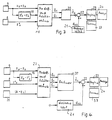
- eine schematische Darstellung eines ersten Ausführungsbeispiels; und
- Figur 4:
- eine schematische Darstellung eines zweiten Ausführungsbeispiels.
- Figure 1:
- is a schematic representation of the vibration system formed by the vehicle body and the vehicle wheel;
- Figure 2:
- a diagram showing the relationship between normalized vertical acceleration of the vehicle body and normalized dynamic wheel load fluctuation with different physical coefficients as parameters;
- Figure 3:
- a schematic representation of a first embodiment; and
- Figure 4:
- is a schematic representation of a second embodiment.
Figur 1 stellt schematisch das aus einem Fahrzeugaufbau
1, einer Feder 2, einem Schwingungsdämpfer (Stoßdämpfer)
3 und einem Rad 7 bestehende Schwingungssystem
der Radaufhängung des Fahrzeugs dar. Das Rad 7
ist ebenfalls als Schwingungssystem dargestellt mit
einer Masse mR und einer Federsteifigkeit cR' die im
wesentlichen vom Reifendruck pR abhängt. Die Federsteifigkeit
der Feder 2 wird mit cA bezeichnet. dA,
ist der Dämpfungskoeffizient des Schwingungsdämpfers
3. Die vertikalen Wege des Aufbaus 1 und des Rades 7
sind mit zA, und zR bezeichnet. Die Radlast FZ setzt
sich aus der Gewichtskraft EZstat und den dynamischen
Radlastschwankungen FZdyn wie folgt zusammen:
Figur 2 zeigt den prinzipiellen Zusammenhang zwischen
der normierten vertikalen Aufbaubeschleunigung zA"/g
und der normierten dynamischen Radlastschwankung
Fzdyn/Fzstat. Im Sinne einer Minimierung beider Werte,
d.h. einer möglichst geringen Aufbaubeschleunigung
zur Erzielung eines größeren Komforts und einer möglichst
geringen dynamischen Radlastschwankung zur
Erzielung einer größeren Fahrsicherheit soll der
Dämpfungskoeffizient dA möglichst in einen hervorgehobenen
Bereich 15 einer Dämpfungskoeffizientenkurve
16 liegen. Die Kurve 16 ändert sich mit Änderungen
der Masse mA des Aufbaus 1 und der Federsteifigkeiten
cA des Aufbaus und cR des Reifens 7. Der Schätzwert
des physikalischen Dämpfungskoeffizienten dA läßt
sich auf verschiedene Art und Weise aus den Meßwerten
bestimmen.FIG. 2 shows the basic relationship between the normalized vertical body acceleration z A "/ g and the normalized dynamic wheel load fluctuation F zdyn / F zstat . In the sense of minimizing both values, ie as little body acceleration as possible to achieve greater comfort and the smallest possible dynamic wheel load fluctuation in order to achieve greater driving safety, the damping coefficient d A should, if possible, be in a highlighted
Bei dem Ausführungsbeispiel nach Figur 3 wird von
einem Sensor 9 die Einfederung, d.h. die Wegdifferenz
zwischen Rad 7 und Aufbau 1 einerseits zu einem mathematischen
Modell- und Schätzrechner 18 und andererseits
einer Rechnerstufe 19-zur Berechnung der
Differenz zwischen der Radgeschwindigkeit Z'R und der
Aufbaugeschwindigkeit Z'R geleitet. Von einem Beschleunigungssensor
8 wird die Aufbaubeschleunigung
Z"A dem mathematischen Modell zugeführt. Der mathematische
Modellrechner entwickelt die Gleichung
Durch ein an sich bekanntes Parameterschätzverfahren werden die Parameter â0 und â1 geschätzt. Ein geeignetes Verfahren zum Schätzen von Parametern ist beispielsweise in Isermann R.: "Estimation of Physical Parameters for Dynamic Processes with Application to an Industrial Robot", International Journal of Control, Vol. 55 (1992) No. 6, pages 1287 - 1291, angegeben.The parameters â 0 and â 1 are estimated by a known parameter estimation method. A suitable method for estimating parameters is, for example, in Isermann R .: "Estimation of Physical Parameters for Dynamic Processes with Application to an Industrial Robot", International Journal of Control, Vol. 55 (1992) No. 6, pages 1287 - 1291.
Aus den geschätzten Parametern â0 und â1 wird in einem
Rechner 20 ein geschätzter Istwert des Dämpfungskoeffizienten
d andA berechnet nach der Formel d andA = â1. mA. In
einem Subtrahierer 21 wird der so berechnete Dämpfungskoeffizient
von einem aus einem Speicher 22 zugeführten
Referenzwert dAS subtrahiert. Die Differenz
wird einem Vergleicher 23 zugeführt, der feststellt,
ob die Differenz in einem Toleranzbereich liegt, der
von einem Speicher 37 geliefert wird. Eine Anzeigeeinrichtung
24 zeigt das Ergebnis der Qualitätsprüfung
an.From the estimated parameters â 0 and â 1 , an estimated actual value of the damping coefficient d and A is calculated in a
Der im Speicher 21 enthaltene Referenzwert dAS des
Dämpfungskoeffizienten ist ausgewählt aus dem Bereich
15 der Dämpfungskoeffizientenkurve 16 in Figur 2,
deren Verlauf vom jeweiligen Fahrzeugtyp abhängig
ist. Wenn der Dämpfungskoeffizient mehr in Richtung
auf erhöhten Fahrkomfort geprüft werden soll, wird
der Sollwert auf den Minimalwert der normierten Beschleunigung
des Fahrzeugaufbaus 1 innerhalb des Kurvenbereichs
15 gelegt. Wenn die Prüfung des Schwingungsdämpfers
mehr in Richtung auf Fahrzeugsicherheit
durchgeführt wird, wird der Sollwert so festgelegt,
daß die normierte dynamische Radlastschwankung einen
Minimalwert hat. Letzterer Sollwert wird bevorzugt
für den Dämpfungskoeffizienten gewählt, da, wie die
Kurvendarstellung in Figur 2 zeigt, hierbei auch noch
ein ausreichender Fahrkomfort, d.h. eine niedrige
normierte Beschleunigung des Fahrzeugaufbaus, erreicht
wird. The reference value d AS of the damping coefficient contained in the
Der im Speicher 37 gespeicherte Toleranzbereich für
den zulässigen Dämpfungskoeffizienten dA wird so bemessen,
daß er den Kurvenbereich 15 der Dämpfungskoeffizientenkurve
16 der Figur 2 umfaßt.The tolerance range for the permissible damping coefficient d A stored in the
Bei dem in Figur 4 dargestellten Ausführungsbeispiel
ist außer den Sensoren 8, 9 ein weiterer Sensor 26
vorgesehen, der die Einfederung des Reifens mißt,
also die Differenz der Unebenheiten der Fahrbahn,
welche z.B. durch eine Rolle mit Schlagleiste simuliert
werden kann, und des Absolutweges des Rades.
Die gemessenen Größen sowie die im Rechner 19 berechnete
Geschwindigkeitsdifferenz werden einem Modellund
Schätzrechner 27 zugeführt, der die Gleichung
Aus der Kräftebilanz des Aufbaus läßt sich eine weitere
Schätzgleichung auch direkt ableiten:
So lassen sich ohne weitere Meßgrößen die geschätzten Koeffizienten d andA, c andA und die Aufbaumasse mA bestimmen. (zR"-zA") kann aus der Meßgröße (zR-zA) berechnet werden.In this way, the estimated coefficients d and A , c and A and the body mass m A can be determined without further measured variables. (z R "-z A ") can be calculated from the measured variable (z R -z A ).
Die Auswertung von dA und dAS für die Schwingungsdämpferprüfung erfolgt wie beim Ausführungsbeispiel der Figur 3.The evaluation of d A and d AS for the vibration damper test is carried out as in the exemplary embodiment in FIG. 3.
Im folgenden sind mögliche Gleichungen zur Schätzung
der Parameter aufgeführt unabhängig davon, ob sie im
Zusammenhang mit den Ausführungsbeispielen bereits
erwähnt sind:
Mit diesen Schätzgleichungen lassen sich aus gemessenen
Prozeßgrößen unter Verwendung von bekannten Koeffizienten
die folgenden Koeffizienten gemäß folgender
Tabelle schätzen:
Eine weitere Schätzgleichung enthält die dynamische
Radlastschwankung RZdyn und die Einfederung zR-zA. Diese
Gleichung läßt sich ebenfalls vorteilhaft für
Schwingungsdämpferuntersuchungen auf einem Prüfstand
verwenden, wobei FZdyn leicht meßbar ist. Die Gleichung
lautet:
Die Summe (mA+mR) läßt sich in einfacher Weise durch statische Messung der Gewichtskraft FZstat bestimmen, während die Einfederung durch ein geeignetes Meßgerät gemessen werden kann.The sum (m A + m R ) can be determined in a simple manner by static measurement of the weight F Zstat , while the deflection can be measured by a suitable measuring device.
Die Erfindung schafft ein Verfahren zur Prüfung des Schwingungsdämpfers des Fahrwerks eines Kraftfahrzeugs, bei dem Prozeßgrößen, welche mit einer vertikalen Bewegung des Fahrzeugs zusammenhängen, einem mathematischen Modell zugeführt werden, das den Zusammenhang zwischen der vertikalen Beschleunigung des Fahrzeugrades und des Fahrzeugaufbaus einerseits und geschätzen Parametern, die nach einem an sich bekannten Parameter-Schätzverfahren geschätzt werden, andererseits darstellt, und bei dem hieraus der Dämpfungskoeffizient als Schätzwert gewonnen werden und der Vergleich zwischen geschätztem Dänpfungskoeffizienten und Referenzwert für die Schwingungsdämpferprüfung durchgeführt wird.The invention provides a method for testing the Vibration damper of the chassis of a motor vehicle, in the process variables, which with a vertical Movement of the vehicle related, one mathematical model can be fed that the context between the vertical acceleration of the Vehicle wheel and the vehicle body on the one hand and estimated parameters based on a known Parameter estimation methods are estimated, on the other hand represents, and from which the damping coefficient be obtained as an estimate and the comparison between the estimated damping coefficient and reference value for the vibration damper test is carried out.
Claims (1)
- A method of testing a shock absorber (3) of a motor vehicle, wherein by footprint excitation oscillations are transmitted by way of a motor vehicle wheel (7) standing on a wheel support surface to the motor vehicle wheel suspension including the shock absorber (3) to be tested and in that operation the damping characteristic is determined,
characterised in that
the differences of the movement amplitudes (ZR-ZA) and speeds (Z'R-Z'A) of the wheel (7) and those of the vehicle body (1) are related to the acceleration of the wheel (Z"R) or the dynamic wheel support force and the damping coefficient (dA) is estimated from said relationship in accordance with a parameter estimation process, and that for quality testing of the shock absorber (3) the estimated damping coefficient is compared to-a reference value and for quality testing it is ascertained whether a deviation from the reference value lies within a tolerance range.
Applications Claiming Priority (2)
| Application Number | Priority Date | Filing Date | Title |
|---|---|---|---|
| DE19934305048 DE4305048C2 (en) | 1993-02-18 | 1993-02-18 | Method for testing a vibration damper of a motor vehicle |
| DE4305048 | 1993-02-18 |
Publications (3)
| Publication Number | Publication Date |
|---|---|
| EP0611960A2 EP0611960A2 (en) | 1994-08-24 |
| EP0611960A3 EP0611960A3 (en) | 1995-06-28 |
| EP0611960B1 true EP0611960B1 (en) | 1998-05-20 |
Family
ID=6480816
Family Applications (1)
| Application Number | Title | Priority Date | Filing Date |
|---|---|---|---|
| EP19940102441 Expired - Lifetime EP0611960B1 (en) | 1993-02-18 | 1994-02-17 | Method for examining a vibration damper of a vehicle |
Country Status (3)
| Country | Link |
|---|---|
| EP (1) | EP0611960B1 (en) |
| DE (1) | DE4305048C2 (en) |
| ES (1) | ES2117161T3 (en) |
Cited By (3)
| Publication number | Priority date | Publication date | Assignee | Title |
|---|---|---|---|---|
| EP2136195A2 (en) | 2008-06-17 | 2009-12-23 | Robert Bosch Gmbh | Method and device for testing an installed shock absorber of a motor vehicle |
| DE102010038905A1 (en) | 2010-08-04 | 2012-02-09 | Robert Bosch Gmbh | Method and device for determining wheel and body movements of a vehicle |
| EP3505903A1 (en) | 2017-12-30 | 2019-07-03 | EMT-Systems Sp.z o.o. | A method for detecting manufacturing defects of hydraulic dampers, especially shock absorbers, and a device for detecting manufacturing defects of hydraulic dampers, especially shock absorbers |
Families Citing this family (21)
| Publication number | Priority date | Publication date | Assignee | Title |
|---|---|---|---|---|
| JP2962046B2 (en) * | 1992-05-15 | 1999-10-12 | 日産自動車株式会社 | Suspension vibration input estimation device |
| DE4432286A1 (en) | 1994-09-10 | 1996-03-14 | Roland Mueller | Device and method for testing vehicle shock absorbers |
| DE4431794A1 (en) * | 1994-09-06 | 1996-03-07 | Langlechner Richard Gmbh | Method and device for determining the properties of shock absorbers installed in a motor vehicle |
| DE4432892A1 (en) * | 1994-09-15 | 1996-03-21 | Bayerische Motoren Werke Ag | Method for determining the state of a suspension component |
| DE4432893A1 (en) * | 1994-09-15 | 1996-03-21 | Bayerische Motoren Werke Ag | Method for controlling or monitoring wheel suspension components in motor vehicles |
| IT1291730B1 (en) * | 1997-05-15 | 1999-01-21 | Vamag Srl | METHOD FOR TESTING THE SUSPENSION OF A MOTOR VEHICLE AND DEVICE USING THIS METHOD |
| DE19823369A1 (en) * | 1998-05-18 | 1999-12-09 | Bosch Gmbh Robert | Method for testing wheel suspension of motor vehicle |
| DE19823367A1 (en) * | 1998-05-18 | 1999-12-09 | Bosch Gmbh Robert | Method of testing motor vehicle wheel suspensions enables reliable, time-saving measurement value acquisition |
| WO1999060368A1 (en) * | 1998-05-18 | 1999-11-25 | Robert Bosch Gmbh | Method and device for testing wheel suspensions |
| SE0203382L (en) | 2002-11-15 | 2004-05-16 | Volvo Lastvagnar Ab | System and method for diagnosing shock absorbers |
| DE102008041745B4 (en) * | 2008-09-01 | 2021-01-14 | Beissbarth Gmbh | Method and device for testing at least one vibration damper of a motor vehicle in the installed state |
| DE102009028368A1 (en) | 2008-09-01 | 2010-03-04 | Robert Bosch Gmbh | Method and device for testing a vibration damper of a motor vehicle when installed |
| DE102008041732A1 (en) | 2008-09-01 | 2010-03-04 | Robert Bosch Gmbh | Chassis testing device and method for testing a chassis |
| DE102010003205B4 (en) * | 2010-03-24 | 2020-01-16 | Ford Global Technologies, Llc | Method for determining the vertical acceleration, the longitudinal angular acceleration and the transverse angular acceleration of a body, in particular a motor vehicle |
| CZ303605B6 (en) * | 2010-05-03 | 2013-01-02 | Vysoké ucení technické v Brne | Method of determining damping properties of automobile axles and apparatus for making the same |
| DE102011087594A1 (en) * | 2011-12-01 | 2013-06-06 | Bayerische Motoren Werke Aktiengesellschaft | Method for functional monitoring of vibration damper for wheel of passenger car, involves obtaining correct function and incorrect function of vibration damper, such that recognized incorrect function is provided in display |
| CN103245513B (en) * | 2013-04-10 | 2015-06-10 | 暨南大学 | Dynamic quality detection method for whole assembly of automobile products |
| CN104330234A (en) * | 2014-09-24 | 2015-02-04 | 江南大学 | Novel method for indirectly determining equivalent dynamic stiffness of package coupling interface |
| CN104330352A (en) * | 2014-09-24 | 2015-02-04 | 江南大学 | High-precision method of indirectly measuring equivalent dynamic stiffness in multipoint-connecting packaging coupling interface |
| DE102015217916B4 (en) * | 2015-09-18 | 2017-06-08 | Schaeffler Technologies AG & Co. KG | Motor vehicle and method for determining a wheel contact force for each wheel of a motor vehicle |
| DE102019128850A1 (en) * | 2019-10-25 | 2021-04-29 | Bayerische Motoren Werke Aktiengesellschaft | Method for determining a load and / or wheel loads of a motor vehicle and a control device and motor vehicle therefor |
Family Cites Families (8)
| Publication number | Priority date | Publication date | Assignee | Title |
|---|---|---|---|---|
| JPS55114930A (en) * | 1979-02-28 | 1980-09-04 | Hitachi Ltd | Stable control unit of vibration test machine |
| US4376387A (en) * | 1980-07-24 | 1983-03-15 | Products And Patents Ltd. | Dynamic shock absorber evaluator |
| GB8815167D0 (en) * | 1988-06-25 | 1988-08-03 | Liquid Levers Ltd | Method & apparatus for testing shock absorbers &/suspension systems in or on motor vehicles |
| NL194247C (en) * | 1988-09-13 | 2001-10-02 | Garage Equip Maintenance | Device for testing the wheel suspension of a vehicle. |
| DE3930555A1 (en) * | 1989-06-29 | 1991-01-03 | Bosch Gmbh Robert | SEMIAACTIVE CHASSIS CONTROL |
| JP2569841B2 (en) * | 1989-11-14 | 1997-01-08 | トヨタ自動車株式会社 | Suspension control device |
| NL9001989A (en) * | 1990-09-10 | 1992-04-01 | Analogic Eng Bv | DEVICE FOR TESTING THE WHEEL SUSPENSION OF A VEHICLE. |
| NL9002780A (en) * | 1990-12-17 | 1992-07-16 | Analogic Eng Bv | DEVICE FOR TESTING THE WHEEL SUSPENSION OF A VEHICLE. |
-
1993
- 1993-02-18 DE DE19934305048 patent/DE4305048C2/en not_active Expired - Fee Related
-
1994
- 1994-02-17 EP EP19940102441 patent/EP0611960B1/en not_active Expired - Lifetime
- 1994-02-17 ES ES94102441T patent/ES2117161T3/en not_active Expired - Lifetime
Cited By (5)
| Publication number | Priority date | Publication date | Assignee | Title |
|---|---|---|---|---|
| EP2136195A2 (en) | 2008-06-17 | 2009-12-23 | Robert Bosch Gmbh | Method and device for testing an installed shock absorber of a motor vehicle |
| DE102008002484A1 (en) | 2008-06-17 | 2009-12-24 | Robert Bosch Gmbh | Method for testing a vibration damper of a motor vehicle when installed and vibration damper test system for a motor vehicle |
| DE102010038905A1 (en) | 2010-08-04 | 2012-02-09 | Robert Bosch Gmbh | Method and device for determining wheel and body movements of a vehicle |
| WO2012016813A1 (en) | 2010-08-04 | 2012-02-09 | Robert Bosch Gmbh | Method and device for determining wheel movements and body movements of a vehicle |
| EP3505903A1 (en) | 2017-12-30 | 2019-07-03 | EMT-Systems Sp.z o.o. | A method for detecting manufacturing defects of hydraulic dampers, especially shock absorbers, and a device for detecting manufacturing defects of hydraulic dampers, especially shock absorbers |
Also Published As
| Publication number | Publication date |
|---|---|
| ES2117161T3 (en) | 1998-08-01 |
| DE4305048C2 (en) | 2002-09-26 |
| DE4305048A1 (en) | 1994-08-25 |
| EP0611960A2 (en) | 1994-08-24 |
| EP0611960A3 (en) | 1995-06-28 |
Similar Documents
| Publication | Publication Date | Title |
|---|---|---|
| EP0611960B1 (en) | Method for examining a vibration damper of a vehicle | |
| EP2136195B1 (en) | Method and device for testing an installed shock absorber of a motor vehicle | |
| DE69121155T2 (en) | Device for checking the wheel suspension of a vehicle | |
| DE3151254C2 (en) | Test device for the tire air pressure of wheels on vehicles and method for such a device | |
| EP0554779B1 (en) | Procedure for testing vehicle components, in particular the individual wheel suspensions | |
| EP0756701B1 (en) | Process for determining the characteristics of a motor vehicle's built-in shock absorbers | |
| DE69525916T2 (en) | Tire pressure estimation device based on the vibration component of the rotational speed of vehicle wheels | |
| DE112010005840B4 (en) | Vehicle control device | |
| DE10017506C2 (en) | Method for determining the wheel contact force of a motor vehicle | |
| DE102014106086A1 (en) | Roller test bench and operating method for a chassis dynamometer | |
| DE102006016764B4 (en) | Method for testing a motor vehicle steering system | |
| EP1591770A1 (en) | Method for inspecting shock absorbers in motor vehicles | |
| DE102008041745B4 (en) | Method and device for testing at least one vibration damper of a motor vehicle in the installed state | |
| DE102010003205A1 (en) | Method for determining the vertical acceleration, the longitudinal angular acceleration and the transverse angular acceleration of a body, in particular of a motor vehicle | |
| DE4218087C2 (en) | Method for determining the damping coefficient of a wheel suspension of a motor vehicle | |
| EP0779972B1 (en) | Testing a characteristic of a shock absorber whilst mounted on a vehicle | |
| DE3912144A1 (en) | METHOD AND DEVICE FOR DETERMINING THE AXLE LOAD OF A VEHICLE | |
| EP2159561A2 (en) | Method and device for testing a built-in vibration damper of a motor vehicle | |
| EP0736439B1 (en) | Running gear for railway vehicles | |
| EP3966544B1 (en) | Method and test stand for determining tire properties | |
| DE4439997C1 (en) | Automobile shock absorber damping characteristics testing device | |
| EP2520921A2 (en) | Method for diagnosing a functional state of a component of an active suspension of a motor vehicle | |
| DE10337212B4 (en) | System and method for determining a loading state of a vehicle or a trailer | |
| DE19651162A1 (en) | Vibration damper for vehicle monitor system | |
| DE102008058771A1 (en) | Method and device for unbalance test on at least one wheel of a motor vehicle |
Legal Events
| Date | Code | Title | Description |
|---|---|---|---|
| PUAI | Public reference made under article 153(3) epc to a published international application that has entered the european phase |
Free format text: ORIGINAL CODE: 0009012 |
|
| AK | Designated contracting states |
Kind code of ref document: A2 Designated state(s): ES FR GB IT |
|
| PUAL | Search report despatched |
Free format text: ORIGINAL CODE: 0009013 |
|
| AK | Designated contracting states |
Kind code of ref document: A3 Designated state(s): ES FR GB IT |
|
| 17P | Request for examination filed |
Effective date: 19951024 |
|
| GRAG | Despatch of communication of intention to grant |
Free format text: ORIGINAL CODE: EPIDOS AGRA |
|
| GRAG | Despatch of communication of intention to grant |
Free format text: ORIGINAL CODE: EPIDOS AGRA |
|
| GRAH | Despatch of communication of intention to grant a patent |
Free format text: ORIGINAL CODE: EPIDOS IGRA |
|
| 17Q | First examination report despatched |
Effective date: 19970728 |
|
| GRAH | Despatch of communication of intention to grant a patent |
Free format text: ORIGINAL CODE: EPIDOS IGRA |
|
| GRAA | (expected) grant |
Free format text: ORIGINAL CODE: 0009210 |
|
| AK | Designated contracting states |
Kind code of ref document: B1 Designated state(s): ES FR GB IT |
|
| ITF | It: translation for a ep patent filed | ||
| ET | Fr: translation filed | ||
| REG | Reference to a national code |
Ref country code: ES Ref legal event code: FG2A Ref document number: 2117161 Country of ref document: ES Kind code of ref document: T3 |
|
| GBT | Gb: translation of ep patent filed (gb section 77(6)(a)/1977) |
Effective date: 19980721 |
|
| PLBE | No opposition filed within time limit |
Free format text: ORIGINAL CODE: 0009261 |
|
| STAA | Information on the status of an ep patent application or granted ep patent |
Free format text: STATUS: NO OPPOSITION FILED WITHIN TIME LIMIT |
|
| 26N | No opposition filed | ||
| REG | Reference to a national code |
Ref country code: GB Ref legal event code: 732E |
|
| REG | Reference to a national code |
Ref country code: FR Ref legal event code: TP |
|
| REG | Reference to a national code |
Ref country code: GB Ref legal event code: IF02 |
|
| PGFP | Annual fee paid to national office [announced via postgrant information from national office to epo] |
Ref country code: GB Payment date: 20030212 Year of fee payment: 10 Ref country code: ES Payment date: 20030212 Year of fee payment: 10 |
|
| PGFP | Annual fee paid to national office [announced via postgrant information from national office to epo] |
Ref country code: FR Payment date: 20030218 Year of fee payment: 10 |
|
| PG25 | Lapsed in a contracting state [announced via postgrant information from national office to epo] |
Ref country code: GB Free format text: LAPSE BECAUSE OF NON-PAYMENT OF DUE FEES Effective date: 20040217 |
|
| PG25 | Lapsed in a contracting state [announced via postgrant information from national office to epo] |
Ref country code: ES Free format text: LAPSE BECAUSE OF NON-PAYMENT OF DUE FEES Effective date: 20040218 |
|
| GBPC | Gb: european patent ceased through non-payment of renewal fee |
Effective date: 20040217 |
|
| PG25 | Lapsed in a contracting state [announced via postgrant information from national office to epo] |
Ref country code: FR Free format text: LAPSE BECAUSE OF NON-PAYMENT OF DUE FEES Effective date: 20041029 |
|
| REG | Reference to a national code |
Ref country code: FR Ref legal event code: ST |
|
| PG25 | Lapsed in a contracting state [announced via postgrant information from national office to epo] |
Ref country code: IT Free format text: LAPSE BECAUSE OF NON-PAYMENT OF DUE FEES Effective date: 20050217 |
|
| REG | Reference to a national code |
Ref country code: ES Ref legal event code: FD2A Effective date: 20040218 |