EP0891836B1 - Electric resistance welding system - Google Patents
Electric resistance welding system Download PDFInfo
- Publication number
- EP0891836B1 EP0891836B1 EP98305423A EP98305423A EP0891836B1 EP 0891836 B1 EP0891836 B1 EP 0891836B1 EP 98305423 A EP98305423 A EP 98305423A EP 98305423 A EP98305423 A EP 98305423A EP 0891836 B1 EP0891836 B1 EP 0891836B1
- Authority
- EP
- European Patent Office
- Prior art keywords
- welding
- workpieces
- per unit
- power
- unit volume
- Prior art date
- Legal status (The legal status is an assumption and is not a legal conclusion. Google has not performed a legal analysis and makes no representation as to the accuracy of the status listed.)
- Expired - Lifetime
Links
- 238000003466 welding Methods 0.000 title claims description 102
- 238000000034 method Methods 0.000 claims description 15
- 239000000463 material Substances 0.000 description 14
- 238000010438 heat treatment Methods 0.000 description 8
- 238000010304 firing Methods 0.000 description 6
- 230000001276 controlling effect Effects 0.000 description 4
- 238000002474 experimental method Methods 0.000 description 4
- 238000012545 processing Methods 0.000 description 4
- 239000000203 mixture Substances 0.000 description 3
- 238000012544 monitoring process Methods 0.000 description 3
- XEEYBQQBJWHFJM-UHFFFAOYSA-N Iron Chemical compound [Fe] XEEYBQQBJWHFJM-UHFFFAOYSA-N 0.000 description 2
- 238000013021 overheating Methods 0.000 description 2
- 238000010276 construction Methods 0.000 description 1
- 230000007547 defect Effects 0.000 description 1
- 238000010586 diagram Methods 0.000 description 1
- 229910052742 iron Inorganic materials 0.000 description 1
- 238000012986 modification Methods 0.000 description 1
- 230000004048 modification Effects 0.000 description 1
- 238000013441 quality evaluation Methods 0.000 description 1
- 230000001105 regulatory effect Effects 0.000 description 1
- 238000004904 shortening Methods 0.000 description 1
Images
Classifications
-
- B—PERFORMING OPERATIONS; TRANSPORTING
- B23—MACHINE TOOLS; METAL-WORKING NOT OTHERWISE PROVIDED FOR
- B23K—SOLDERING OR UNSOLDERING; WELDING; CLADDING OR PLATING BY SOLDERING OR WELDING; CUTTING BY APPLYING HEAT LOCALLY, e.g. FLAME CUTTING; WORKING BY LASER BEAM
- B23K11/00—Resistance welding; Severing by resistance heating
- B23K11/24—Electric supply or control circuits therefor
- B23K11/25—Monitoring devices
- B23K11/252—Monitoring devices using digital means
- B23K11/258—Monitoring devices using digital means the measured parameter being a voltage
Definitions
- the present teachings relate to a technique for welding workpieces by employing electric resistance heating caused by conducting electric current through the workpieces.
- Known welding systems of this type generally comprise a pair of electrodes for retaining workpieces therebetween, an electric power source for generating a welding current that can be conducted through the workpieces by the pair of electrodes, and a controller for controlling the electric power source and the current generated thereby.
- the welding power In order to produce a sturdy weld, the welding power must be controlled. If the welding power applied to the workpieces is too great, the weld site may spatter and thereby prohibit a sturdy weld. On the other hand, if the welding power is too small, insufficient heating at the weld site reduces the weld quality.
- welding power has been controlled by adjusting either welding current or welding voltage.
- predetermined values have been utilized to control the amount of power that is applied to the weld site.
- welding current generally is used as such a predetermined value.
- the welding current is monitored and increased if it is too little to produce a sturdy weld.
- the welding current is reduced if the welding power is too great to prevent overheating of the workpiece.
- a standard predetermined value depends upon the composition of the workpiece materials, including whether the workpieces are coated or not.
- predetermined welding current values may be too great or too little as a result of variation in workpiece compositions. Therefore, a standard predetermined current value must be determined independently for every kind of workpieces that will-be welded. In application of these known welding techniques, the determination of the standard current value typically requires a large number of experiments.
- an object of the present teachings to provide a predetermined value for welding workpieces that is not affected by variations in workpiece materials and in the wear of electrodes so as to thereby avoid the necessity of compensating for variations in workpiece materials and in the wear of the electrodes.
- a predetermined value for welding workpieces that is not affected by variations in workpiece materials and in the wear of electrodes so as to thereby avoid the necessity of compensating for variations in workpiece materials and in the wear of the electrodes.
- a total power per unit volume of the workpieces is used as the predetermined value.
- the contact area between the electrodes and the workpiece varies as the electrode is worn, it was previously considered to be difficult to calculate a single predetermined total power per unit volume value for workpieces that could be utilized for the life of the electrodes.
- the welding power applied to the workpieces also changes in accordance with the change in contact area. But, after making certain calculations, these changes can be made to cancel out and not be relevant to the predetermined total power value that is applied to the workpieces.
- the preferred total power per unit volume of the workpieces does not vary as the contact area of the electrode with the workpiece changes due to wear.
- the total power per unit volume is used as the predetermined value to control the welding power according to the present teachings.
- a predetermined standard value for the predetermined value is determined that yields sturdy welds for a particular workpiece material, this predetermined standard value yields sturdy welds regardless of variations in the workpiece materials and in wear of the electrodes, thereby permitting sturdy welds to be obtained consistently.
- the total power per unit volume of the workpieces is calculated based upon the combined thickness of the workpieces that will be welded and the time necessary to produce a sturdy weld. Variations in the workpiece materials and in wear of the electrodes are generally not relevant to the present calculations. Most workpieces then can be satisfactorily welded utilizing this technique.
- power per unit volume and per unit time during the welding period is calculated according to a model in which the weld power is set to be a first value during the first half of the welding period and a second lower value during the last half of the welding period.
- the power per unit volume applied to the workpieces during the welding period is measured. This measured value can then be compared to the value calculated according to the first aspect to determine whether a sturdy weld has been made or not.
- weld quality can consistently be determined without consideration of variations in workpieces materials and in wear of the electrodes.
- the present teachings permit weld defects to be easily and accurately identified.
- the welding current flows through a cross-section of the workpieces that is columnar in shape and has the cross-sectional area "S" and the resistance of the workpieces in that cross-section causes heating therethrough when the current is applied.
- power (q) per unit volume and per unit time can be calculated based upon the inter-electrode voltage V and the total thickness t of the workpieces and therefore, this value is not affected by the contact area S of the electrode with the workpiece.
- Equation (3) power q is calculated based upon the inter-electrode voltage V.
- the contact area S of the electrode with the workpiece is not relevant to the calculation of the power per unit volume per unit time or to the total power Q per unit volume that is applied to the workpieces.
- the total power Q per unit volume is used as a predetermined value. This value is calculated by adding the power q that is applied in each unit of time during the entire welding period. The total welding power that is applied to the workpieces is adjusted based on the predetermined value.
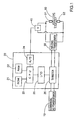
- FIG. 1 is a view showing an overall construction of a resistance welding system that can be utilized with a commercial power source 10.
- a thyristor 26 is provided for changing the welding current by adjusting a firing angle, which means the phase of the AC power supply in which an "on" signal is applied to the thyristor.
- Welding current adjusted by the thyristor 26 is transformed by a welding transformer 30 to a welding power of low voltage and large current.
- the welding current is then conducted across workpieces 60 that are held between a pair of electrodes 51 and 52.
- a clamping force provided to hold the workpieces 60 between the pair of electrodes 51 and 52 can be regulated by a variety of means known in the art.
- a large current is preferably conducted across the workpieces 60 to cause electric resistance heating of the workpieces 60, which resistance heating permits welding of the workpieces 60.
- the voltage across the pair of electrodes 51 and 52 is measured by a voltmeter 40.
- the measured voltage preferably is converted to a digital signal by an A/D converter 24 and then inputted into a CPU 23.
- the CPU 23 may operated according to a control program stored in a ROM 21 such that power per unit time (in the present embodiment, a cycle is the unit of time) and per unit volume can be adjusted by controlling the firing angle of the thyristor.
- a control program stored in a ROM 21 such that power per unit time (in the present embodiment, a cycle is the unit of time) and per unit volume can be adjusted by controlling the firing angle of the thyristor.
- an input/output interface 25 is provided for firing the thyristor 26 by a firing signal outputted from the CPU 23.
- a RAM 22 may be used to temporally store various kinds of data.
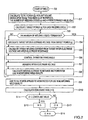
- the control program stored in the ROM 21 serves to execute an operation process shown by a flowchart of FIG. 2. This process is executed when the welding operation is performed.
- step S1 the total power Q per unit volume required to satisfactorily weld the workpieces is calculated based upon the total thickness t and the total amount of time that the welding operation will proceed, which in this case is the total number of welding cycles c of the commercial AC power 10.
- the total power Q per unit volume required to produce sturdy welds can be determined based upon the total thickness of the workpieces and the welding time (the number of welding cycles c):
- Q Q 0 + k . c/t
- c the number of welding cycles
- t the total thickness of the workpieces
- Q 0 is a constant preferably ranging between 1-100J/mm 3
- k is a coefficient preferably ranging between 0-10J/ c . mm 2 ).
- a value of the coefficient k may be indicated by the ratio resistive heating power /(welding period . mm 2 ).
- equation (4) is preferred example for expressing the calculation that are utilized according to the present teaching and that other approximation equations for obtaining an optimum value for Q may be utilized without affecting the results obtained.
- the optimum value for Q may be calculated from a prepared table in which the value Q can be located by the total thickness of the workpieces and the welding time.
- step S2 of FIG. 2 power q per cycle is calculated to ensure that the desirable total power Q calculated in step S1 is applied to the workpieces.
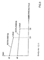
- FIG. 3 illustrates a preferred relationship between the number of welding cycles and amount of power q applied to the workpieces during each cycle.
- the number of welding cycles depends on the total thickness of the workpieces . That is, a thin workpiece may only require a short welding time, while a thick workpiece may require a long welding time.
- C3 designates a preferred number of welding cycles when the total thickness of the workpieces is 3mm
- C5 designates a preferred number of welding cycles when the total thickness of the workpieces is 5mm.
- Line P3 illustrates a preferred cycle-by-cycle variation of power q that may be utilized to achieve the desired total power Q3 when the total workpiece thickness is 3mm.
- a first amount of power q3 is applied. Over the course of welding the workpieces, the amount of power applied in each cycle is gradually reduced until about 85% of the initial power is applied during the final welding cycle.
- Value Q3 designates total power calculated by adding the power q that is applied to the workpieces in each of the C3 cycles.
- Line P5 and total power Q5 are shown in FIG. 3 for a workpiece having a thickness is 5mm. Again, over the course of welding the workpieces, the amount of power applied in each cycle is gradually reduced until about 85% of the initial power is applied during the final welding cycle. Value Q5 designates total power calculated by adding the power q that is applied to the workpieces in each of the C5 cycles.
- the initial value of the power q is set to be a relatively large value and is gradually reduced in the following cycles .
- the power q may be held constant in each welding cycle.
- the final value of q is set to be 85% of the initial value in this preferred embodiment, which has the advantageous feature of producing strong welds while simultaneously shortening the welding time and substantially reducing the possibility of weld spattering.
- Step S3 of FIG. 2 serves to determine whether the welding operation can be terminated.
- the number of the welding cycles is counted during the welding operation, and the welding operation is terminated when the number of cycles reaches a predetermined value, such as is shown by C3 or C5 in FIG. 3.
- Step S4 serves to calculate the inter-electrode voltage V required to yield the desired power q per cycle (unit time) and per unit volume that was calculated in step S2 by using equation (3).
- unit time is seconds.
- power q per cycle is illustrated in FIG. 3. Therefore, it should be noted that the same unit time must be used when calculating the inter-electrode voltage V.
- Step S5 serves to calculate the welding current I required to yield the inter-electrode voltage V calculated in step S4. Subsequently, a firing angle for realizing the welding current I is calculated so that the thyristor 26 may be excited and fired at the calculated firing angle (step S6). By executing step S6, welding current is controlled so as to be identical to the desired current calculated in step S5.
- step S7 the inter-electrode voltage V is measured.
- the inter-electrode resistance and power per unit volume and per unit time (each cycle) for use in monitoring are calculated using the measured voltage from step S7 and the current value I previously calculated in step S5.
- the inter-electrode resistance calculated in step S8 will be used to calculate the current I from the voltage V in step S5 of the next cycle of the welding operation.
- Steps S4 to S8 are repeated for every cycle, and when the number of welding cycles shown by C3 or C5 in FIG. 3 is terminated, step S3 proceeds to YES and the welding operation is terminated. After the termination of the welding period, step S9 is executed, and the power calculated in step S8 for use in monitoring is totaled.
- Steps S10 and S11 serve to evaluate the welding results.
- step S10 the total value of the power that was applied to the workpieces and was calculated in step S9 is divided by the predetermined value for the total power Q that was calculated in step S1.
- coincident rate X the value determined in step S10 (referred to as coincident rate X) exceeds a lower limit value that is slightly lower than 1.0, the predetermined value for the total power has been applied to the workpieces. If so, an OK step is executed, and the process is terminated.
- the welding power is controlled based upon the predetermined value representing the total power per unit volume of the workpieces (corresponding to Q3 or Q5 obtained by integrating line P3 or P4 of FIG. 3). Therefore, the standard value can be set regardless of variations in workpiece materials or in wear of the electrodes, permitting study welds.
- the power per unit time preferably is gradually reduced cycle-by-cycle, thus permitting a rapid rise of the workpiece temperature at the beginning of the welding operation as well as prohibiting excessive heating at the end of the welding operation.
- sturdy welds can be made in a short period of time.
Landscapes
- Engineering & Computer Science (AREA)
- Mechanical Engineering (AREA)
- Resistance Welding (AREA)
- Lining Or Joining Of Plastics Or The Like (AREA)
Applications Claiming Priority (3)
| Application Number | Priority Date | Filing Date | Title |
|---|---|---|---|
| JP188744/97 | 1997-07-14 | ||
| JP18874497A JP3886603B2 (ja) | 1997-07-14 | 1997-07-14 | 単位体積当たりの累積発熱量を指標とする抵抗溶接システム |
| JP18874497 | 1997-07-14 |
Publications (3)
| Publication Number | Publication Date |
|---|---|
| EP0891836A2 EP0891836A2 (en) | 1999-01-20 |
| EP0891836A3 EP0891836A3 (en) | 1999-08-04 |
| EP0891836B1 true EP0891836B1 (en) | 2003-11-05 |
Family
ID=16229020
Family Applications (1)
| Application Number | Title | Priority Date | Filing Date |
|---|---|---|---|
| EP98305423A Expired - Lifetime EP0891836B1 (en) | 1997-07-14 | 1998-07-08 | Electric resistance welding system |
Country Status (5)
| Country | Link |
|---|---|
| US (1) | US6130396A (enExample) |
| EP (1) | EP0891836B1 (enExample) |
| JP (1) | JP3886603B2 (enExample) |
| DE (1) | DE69819420T2 (enExample) |
| ES (1) | ES2209067T3 (enExample) |
Families Citing this family (33)
| Publication number | Priority date | Publication date | Assignee | Title |
|---|---|---|---|---|
| US6609033B1 (en) | 1999-08-03 | 2003-08-19 | Nadex Co. Ltd | Field programmable welding controller |
| JP2002096178A (ja) * | 2000-09-21 | 2002-04-02 | Toyota Auto Body Co Ltd | スポット溶接装置 |
| JP4290448B2 (ja) * | 2003-03-20 | 2009-07-08 | 株式会社ダイヘン | 抵抗溶接制御方法 |
| US7244905B2 (en) * | 2005-06-09 | 2007-07-17 | Daimlerchrysler Corporation | Method for estimating nugget diameter and weld parameters |
| US20070221629A1 (en) * | 2006-03-22 | 2007-09-27 | Vernon Fernandez | Resistance spot welding system and method |
| US20080041827A1 (en) * | 2006-05-26 | 2008-02-21 | Wei Li | Resistance Spot Welding Monitoring System and Method |
| JP4582162B2 (ja) * | 2008-03-05 | 2010-11-17 | 株式会社デンソー | ヒュージング品質管理方法と装置 |
| EP2243602B1 (de) * | 2009-04-22 | 2013-05-15 | KUKA Roboter GmbH | Verfahren und Vorrichtung zur Regelung eines Manipulators |
| AT507774B1 (de) * | 2009-05-14 | 2010-08-15 | Fronius Int Gmbh | Verfahren und vorrichtung zum ermitteln der spannung an den elektroden einer punktschweisszange |
| US9421634B2 (en) | 2011-11-09 | 2016-08-23 | Fca Us Llc | System and method for performing resistance spot welding |
| WO2014136507A1 (ja) | 2013-03-08 | 2014-09-12 | Jfeスチール株式会社 | 抵抗スポット溶接方法 |
| WO2014156290A1 (ja) * | 2013-03-29 | 2014-10-02 | Jfeスチール株式会社 | 抵抗スポット溶接システム |
| CN105612020B (zh) * | 2013-10-04 | 2018-04-10 | 杰富意钢铁株式会社 | 电阻点焊方法 |
| WO2015099192A1 (ja) | 2013-12-27 | 2015-07-02 | Jfeスチール株式会社 | 抵抗スポット溶接方法 |
| EP3130424B1 (en) * | 2014-06-12 | 2018-11-21 | JFE Steel Corporation | Resistance spot welding device and resistance spot welding method |
| JP6108030B2 (ja) | 2014-12-01 | 2017-04-05 | Jfeスチール株式会社 | 抵抗スポット溶接方法 |
| MX379950B (es) | 2015-03-16 | 2025-03-11 | Jfe Steel Corp | Método de soldadura por puntos de resistencia y método para la fabricación de junta soldada por puntos de resistencia. |
| JP5988015B1 (ja) | 2015-04-27 | 2016-09-07 | Jfeスチール株式会社 | 抵抗スポット溶接方法 |
| CN109195737B (zh) | 2016-06-09 | 2021-02-09 | 杰富意钢铁株式会社 | 电阻点焊方法 |
| JP6471841B1 (ja) | 2017-08-18 | 2019-02-20 | Jfeスチール株式会社 | 抵抗スポット溶接方法および溶接部材の製造方法 |
| JP7112819B2 (ja) * | 2017-11-29 | 2022-08-04 | ダイハツ工業株式会社 | スポット溶接方法及びスポット溶接装置 |
| JP6590121B1 (ja) | 2018-02-19 | 2019-10-16 | Jfeスチール株式会社 | 抵抗スポット溶接方法および溶接部材の製造方法 |
| EP3815832B1 (en) | 2018-06-29 | 2024-10-16 | JFE Steel Corporation | Resistance spot welding method and method for manufacturing welded member |
| KR102415946B1 (ko) | 2018-06-29 | 2022-06-30 | 제이에프이 스틸 가부시키가이샤 | 저항 스폿 용접 방법 및 용접 부재의 제조 방법 |
| WO2020004116A1 (ja) | 2018-06-29 | 2020-01-02 | Jfeスチール株式会社 | 抵抗スポット溶接方法および溶接部材の製造方法 |
| JP6904479B2 (ja) * | 2018-11-08 | 2021-07-14 | Jfeスチール株式会社 | 抵抗スポット溶接方法および溶接部材の製造方法 |
| JP6790050B2 (ja) * | 2018-12-13 | 2020-11-25 | 本田技研工業株式会社 | 抵抗溶接評価装置及び抵抗溶接評価方法 |
| EP4023384B1 (en) | 2019-08-29 | 2023-11-22 | JFE Steel Corporation | Resistance spot welding method and weld member production method |
| WO2021070836A1 (ja) | 2019-10-09 | 2021-04-15 | Jfeスチール株式会社 | 抵抗スポット溶接方法および溶接部材の製造方法 |
| MX2022004296A (es) | 2019-10-09 | 2022-05-10 | Jfe Steel Corp | Metodo de soldadura por puntos de resistencia y metodo de produccion de miembro de soldadura. |
| JP7394089B2 (ja) * | 2021-06-04 | 2023-12-07 | ダイハツ工業株式会社 | スポット溶接方法、及びスポット溶接用制御装置 |
| JP7658410B2 (ja) * | 2022-12-13 | 2025-04-08 | Jfeスチール株式会社 | 抵抗スポット溶接方法および溶接部材の製造方法 |
| JP7632749B2 (ja) | 2023-01-23 | 2025-02-19 | Jfeスチール株式会社 | 抵抗スポット溶接方法および溶接継手の製造方法 |
Family Cites Families (29)
| Publication number | Priority date | Publication date | Assignee | Title |
|---|---|---|---|---|
| US3389239A (en) * | 1964-02-11 | 1968-06-18 | Gen Motors Corp | Method and means for testing welding equipment |
| US4028522A (en) * | 1975-04-29 | 1977-06-07 | Martin Marietta Corporation | Multi-mode structural weld monitor on a time base |
| DE2555792A1 (de) * | 1975-12-11 | 1977-06-23 | Eichhorn Friedrich Prof Dr | Verfahren zur qualitaetssicherung der schweissverbindungen beim elektrischen widerstandspunktschweissen |
| US4302653A (en) * | 1980-04-02 | 1981-11-24 | Weltronic Company | Method and apparatus for monitoring and controlling a resistance welding operation |
| US4343980A (en) * | 1980-04-02 | 1982-08-10 | Republic Steel Corporation | Control of welding energy flux density |
| FR2480651B1 (fr) * | 1980-04-21 | 1985-09-06 | Nissan Motor | Procede et systeme pour commander un soudage electrique par resistance |
| DE3018384A1 (de) * | 1980-05-14 | 1981-11-19 | Rossell Electronique S.A., Lausanne | Verfahren zum zubringen von mindestens einer elektrode, zubringevorrichtung und aufnehmer zur ausfuehrung dieses verfahrens sowie verwendung des verfahrens, der zubringevorrichtung und/oder des aufnehmers |
| US4419560A (en) * | 1980-12-19 | 1983-12-06 | Midland-Ross Corporation | Welding control with automatic percent heat adjustment |
| JPS57146485A (en) * | 1981-03-04 | 1982-09-09 | Sanyo Kiko Kk | Current controlling device for resistance welding |
| US4456810A (en) * | 1982-03-29 | 1984-06-26 | Ford Motor Company | Adaptive schedule selective weld control |
| JPS58181488A (ja) * | 1982-04-16 | 1983-10-24 | Sanyo Kiko Kk | 抵抗溶接電流制御方法 |
| US4447700A (en) * | 1982-06-07 | 1984-05-08 | General Electric Company | Resistance spot welder adaptive control |
| US4503311A (en) * | 1983-05-25 | 1985-03-05 | General Motors Corporation | Method and apparatus for detecting the onset of melting in a resistance spot weld |
| US4542277A (en) * | 1984-05-29 | 1985-09-17 | Cecil Dimitrios G | Resistance spot welding gun with weld quality detection feature |
| US4694135A (en) * | 1986-07-09 | 1987-09-15 | General Motors Corporation | Method and apparatus for monitoring and controlling resistance spot welding |
| US4678887A (en) * | 1986-07-09 | 1987-07-07 | General Motors Corporation | Method and apparatus for resistance welding |
| US4792656A (en) * | 1986-09-17 | 1988-12-20 | Miyachi Electronic Company | Invertor type DC resistance welding machine |
| US4711984A (en) * | 1987-03-09 | 1987-12-08 | General Motors Corporation | Ultrasonic method and apparatus for spot weld control |
| US4861960A (en) * | 1988-04-25 | 1989-08-29 | General Electric Company | Real time adaptive control for resistance spot welding process |
| JPH0815669B2 (ja) * | 1988-07-06 | 1996-02-21 | 日本電装株式会社 | 抵抗溶接用制御装置 |
| JPH0284276A (ja) * | 1988-09-21 | 1990-03-26 | Dengensha Mfg Co Ltd | 抵抗溶接機の電極加圧装置 |
| US5081338A (en) * | 1991-02-15 | 1992-01-14 | Unitek Equipment Inc. | Apparatus and method for monitoring weld quality |
| US5111020A (en) * | 1991-05-02 | 1992-05-05 | Ariel Stiebel | Method and apparatus for controlling electrical resistance spot welding |
| US5386092A (en) * | 1991-11-04 | 1995-01-31 | Unitek Equipment Inc. | Fast response weld head |
| JP2510377B2 (ja) * | 1992-05-01 | 1996-06-26 | 株式会社ナ・デックス | 溶接コントロ―ラ |
| JPH0759351B2 (ja) * | 1992-06-10 | 1995-06-28 | 株式会社ナ・デックス | 溶接コントローラ |
| CA2101712C (en) * | 1992-07-31 | 1996-07-09 | Koji Fujii | Resistance welding monitor |
| JPH0760457A (ja) * | 1993-08-26 | 1995-03-07 | Na Detsukusu:Kk | 抵抗溶接機 |
| US5483035A (en) * | 1993-09-21 | 1996-01-09 | Nadex Co., Ltd. | System for and method of controlling resistance welder |
-
1997
- 1997-07-14 JP JP18874497A patent/JP3886603B2/ja not_active Expired - Lifetime
-
1998
- 1998-07-08 ES ES98305423T patent/ES2209067T3/es not_active Expired - Lifetime
- 1998-07-08 DE DE69819420T patent/DE69819420T2/de not_active Expired - Fee Related
- 1998-07-08 EP EP98305423A patent/EP0891836B1/en not_active Expired - Lifetime
- 1998-07-09 US US09/112,054 patent/US6130396A/en not_active Expired - Lifetime
Also Published As
| Publication number | Publication date |
|---|---|
| ES2209067T3 (es) | 2004-06-16 |
| DE69819420T2 (de) | 2004-09-02 |
| JP3886603B2 (ja) | 2007-02-28 |
| JPH1133743A (ja) | 1999-02-09 |
| DE69819420D1 (de) | 2003-12-11 |
| US6130396A (en) | 2000-10-10 |
| EP0891836A3 (en) | 1999-08-04 |
| EP0891836A2 (en) | 1999-01-20 |
Similar Documents
| Publication | Publication Date | Title |
|---|---|---|
| EP0891836B1 (en) | Electric resistance welding system | |
| US6512200B2 (en) | Welding control system | |
| EP0745013B1 (en) | Apparatus using a neural network for power factor calculation | |
| JP2742545B2 (ja) | 抵抗溶接制御方法 | |
| EP0080514A1 (en) | Method and apparatus for controlling resistance welding | |
| EP3053693A1 (en) | Resistance spot welding method | |
| CA2215762A1 (en) | Method of controlling welding conditions of a resistance welder | |
| CA2281299A1 (en) | Method of controlling a welding process and controller therefor | |
| EP1044753A2 (en) | Control apparatus for resistance welding machine | |
| JP3221296B2 (ja) | 抵抗溶接の制御装置および制御方法 | |
| EP0533736B1 (en) | Adaptive stepper | |
| CN108890081B (zh) | 稳定电弧弧长的方法和装置 | |
| US4343980A (en) | Control of welding energy flux density | |
| KR100650611B1 (ko) | 저항용접제어방법 및 장치 | |
| JP3037657B2 (ja) | 抵抗スポット溶接品質管理装置 | |
| US5589088A (en) | Method of regulating DC current in resistance welders | |
| US4387289A (en) | Control system for resistance welding | |
| JP3161315B2 (ja) | 抵抗溶接機の制御装置 | |
| JP3221305B2 (ja) | 抵抗溶接機の制御装置 | |
| JP3163530B2 (ja) | 抵抗溶接の制御装置 | |
| US9421634B2 (en) | System and method for performing resistance spot welding | |
| JPH0242031B2 (enExample) | ||
| EP1750885B1 (en) | Regulating method, apparatus and software for gas metal arc welding with continuously fed electrode | |
| JP2747375B2 (ja) | 抵抗溶接装置 | |
| JPS59199173A (ja) | 短絡移行溶接電源の制御方法および装置 |
Legal Events
| Date | Code | Title | Description |
|---|---|---|---|
| PUAI | Public reference made under article 153(3) epc to a published international application that has entered the european phase |
Free format text: ORIGINAL CODE: 0009012 |
|
| 17P | Request for examination filed |
Effective date: 19980803 |
|
| AK | Designated contracting states |
Kind code of ref document: A2 Designated state(s): DE ES FR GB IT |
|
| AX | Request for extension of the european patent |
Free format text: AL;LT;LV;MK;RO;SI |
|
| PUAL | Search report despatched |
Free format text: ORIGINAL CODE: 0009013 |
|
| AK | Designated contracting states |
Kind code of ref document: A3 Designated state(s): AT BE CH CY DE DK ES FI FR GB GR IE IT LI LU MC NL PT SE |
|
| AX | Request for extension of the european patent |
Free format text: AL;LT;LV;MK;RO;SI |
|
| AKX | Designation fees paid |
Free format text: DE ES FR GB IT |
|
| 17Q | First examination report despatched |
Effective date: 20021028 |
|
| GRAH | Despatch of communication of intention to grant a patent |
Free format text: ORIGINAL CODE: EPIDOS IGRA |
|
| GRAS | Grant fee paid |
Free format text: ORIGINAL CODE: EPIDOSNIGR3 |
|
| GRAA | (expected) grant |
Free format text: ORIGINAL CODE: 0009210 |
|
| AK | Designated contracting states |
Kind code of ref document: B1 Designated state(s): DE ES FR GB IT |
|
| REG | Reference to a national code |
Ref country code: GB Ref legal event code: FG4D |
|
| REF | Corresponds to: |
Ref document number: 69819420 Country of ref document: DE Date of ref document: 20031211 Kind code of ref document: P |
|
| REG | Reference to a national code |
Ref country code: ES Ref legal event code: FG2A Ref document number: 2209067 Country of ref document: ES Kind code of ref document: T3 |
|
| ET | Fr: translation filed | ||
| PLBE | No opposition filed within time limit |
Free format text: ORIGINAL CODE: 0009261 |
|
| STAA | Information on the status of an ep patent application or granted ep patent |
Free format text: STATUS: NO OPPOSITION FILED WITHIN TIME LIMIT |
|
| 26N | No opposition filed |
Effective date: 20040806 |
|
| PG25 | Lapsed in a contracting state [announced via postgrant information from national office to epo] |
Ref country code: IT Free format text: LAPSE BECAUSE OF NON-PAYMENT OF DUE FEES Effective date: 20050708 |
|
| PGFP | Annual fee paid to national office [announced via postgrant information from national office to epo] |
Ref country code: GB Payment date: 20060613 Year of fee payment: 9 |
|
| PGFP | Annual fee paid to national office [announced via postgrant information from national office to epo] |
Ref country code: FR Payment date: 20060630 Year of fee payment: 9 |
|
| PGFP | Annual fee paid to national office [announced via postgrant information from national office to epo] |
Ref country code: DE Payment date: 20060714 Year of fee payment: 9 |
|
| PGFP | Annual fee paid to national office [announced via postgrant information from national office to epo] |
Ref country code: ES Payment date: 20060724 Year of fee payment: 9 |
|
| GBPC | Gb: european patent ceased through non-payment of renewal fee |
Effective date: 20070708 |
|
| PG25 | Lapsed in a contracting state [announced via postgrant information from national office to epo] |
Ref country code: DE Free format text: LAPSE BECAUSE OF NON-PAYMENT OF DUE FEES Effective date: 20080201 |
|
| PG25 | Lapsed in a contracting state [announced via postgrant information from national office to epo] |
Ref country code: GB Free format text: LAPSE BECAUSE OF NON-PAYMENT OF DUE FEES Effective date: 20070708 |
|
| REG | Reference to a national code |
Ref country code: FR Ref legal event code: ST Effective date: 20080331 |
|
| PG25 | Lapsed in a contracting state [announced via postgrant information from national office to epo] |
Ref country code: FR Free format text: LAPSE BECAUSE OF NON-PAYMENT OF DUE FEES Effective date: 20070731 |
|
| REG | Reference to a national code |
Ref country code: ES Ref legal event code: FD2A Effective date: 20070709 |
|
| PG25 | Lapsed in a contracting state [announced via postgrant information from national office to epo] |
Ref country code: ES Free format text: LAPSE BECAUSE OF NON-PAYMENT OF DUE FEES Effective date: 20070709 |