EP0890811B1 - Heat transfer apparatus with two heat exchangers - Google Patents
Heat transfer apparatus with two heat exchangers Download PDFInfo
- Publication number
- EP0890811B1 EP0890811B1 EP98111058A EP98111058A EP0890811B1 EP 0890811 B1 EP0890811 B1 EP 0890811B1 EP 98111058 A EP98111058 A EP 98111058A EP 98111058 A EP98111058 A EP 98111058A EP 0890811 B1 EP0890811 B1 EP 0890811B1
- Authority
- EP
- European Patent Office
- Prior art keywords
- latch
- heat exchanger
- supporting
- arrangement
- mounting
- Prior art date
- Legal status (The legal status is an assumption and is not a legal conclusion. Google has not performed a legal analysis and makes no representation as to the accuracy of the status listed.)
- Expired - Lifetime
Links
Images


Classifications
-
- F—MECHANICAL ENGINEERING; LIGHTING; HEATING; WEAPONS; BLASTING
- F28—HEAT EXCHANGE IN GENERAL
- F28F—DETAILS OF HEAT-EXCHANGE AND HEAT-TRANSFER APPARATUS, OF GENERAL APPLICATION
- F28F9/00—Casings; Header boxes; Auxiliary supports for elements; Auxiliary members within casings
- F28F9/001—Casings in the form of plate-like arrangements; Frames enclosing a heat exchange core
- F28F9/002—Casings in the form of plate-like arrangements; Frames enclosing a heat exchange core with fastening means for other structures
-
- B—PERFORMING OPERATIONS; TRANSPORTING
- B60—VEHICLES IN GENERAL
- B60K—ARRANGEMENT OR MOUNTING OF PROPULSION UNITS OR OF TRANSMISSIONS IN VEHICLES; ARRANGEMENT OR MOUNTING OF PLURAL DIVERSE PRIME-MOVERS IN VEHICLES; AUXILIARY DRIVES FOR VEHICLES; INSTRUMENTATION OR DASHBOARDS FOR VEHICLES; ARRANGEMENTS IN CONNECTION WITH COOLING, AIR INTAKE, GAS EXHAUST OR FUEL SUPPLY OF PROPULSION UNITS IN VEHICLES
- B60K11/00—Arrangement in connection with cooling of propulsion units
- B60K11/02—Arrangement in connection with cooling of propulsion units with liquid cooling
- B60K11/04—Arrangement or mounting of radiators, radiator shutters, or radiator blinds
-
- F—MECHANICAL ENGINEERING; LIGHTING; HEATING; WEAPONS; BLASTING
- F28—HEAT EXCHANGE IN GENERAL
- F28D—HEAT-EXCHANGE APPARATUS, NOT PROVIDED FOR IN ANOTHER SUBCLASS, IN WHICH THE HEAT-EXCHANGE MEDIA DO NOT COME INTO DIRECT CONTACT
- F28D1/00—Heat-exchange apparatus having stationary conduit assemblies for one heat-exchange medium only, the media being in contact with different sides of the conduit wall, in which the other heat-exchange medium is a large body of fluid, e.g. domestic or motor car radiators
- F28D1/02—Heat-exchange apparatus having stationary conduit assemblies for one heat-exchange medium only, the media being in contact with different sides of the conduit wall, in which the other heat-exchange medium is a large body of fluid, e.g. domestic or motor car radiators with heat-exchange conduits immersed in the body of fluid
- F28D1/04—Heat-exchange apparatus having stationary conduit assemblies for one heat-exchange medium only, the media being in contact with different sides of the conduit wall, in which the other heat-exchange medium is a large body of fluid, e.g. domestic or motor car radiators with heat-exchange conduits immersed in the body of fluid with tubular conduits
- F28D1/0408—Multi-circuit heat exchangers, e.g. integrating different heat exchange sections in the same unit or heat exchangers for more than two fluids
- F28D1/0426—Multi-circuit heat exchangers, e.g. integrating different heat exchange sections in the same unit or heat exchangers for more than two fluids with units having particular arrangement relative to the large body of fluid, e.g. with interleaved units or with adjacent heat exchange units in common air flow or with units extending at an angle to each other or with units arranged around a central element
- F28D1/0435—Combination of units extending one behind the other
-
- F—MECHANICAL ENGINEERING; LIGHTING; HEATING; WEAPONS; BLASTING
- F01—MACHINES OR ENGINES IN GENERAL; ENGINE PLANTS IN GENERAL; STEAM ENGINES
- F01P—COOLING OF MACHINES OR ENGINES IN GENERAL; COOLING OF INTERNAL-COMBUSTION ENGINES
- F01P3/00—Liquid cooling
- F01P3/18—Arrangements or mounting of liquid-to-air heat-exchangers
- F01P2003/182—Arrangements or mounting of liquid-to-air heat-exchangers with multiple heat-exchangers
-
- F—MECHANICAL ENGINEERING; LIGHTING; HEATING; WEAPONS; BLASTING
- F01—MACHINES OR ENGINES IN GENERAL; ENGINE PLANTS IN GENERAL; STEAM ENGINES
- F01P—COOLING OF MACHINES OR ENGINES IN GENERAL; COOLING OF INTERNAL-COMBUSTION ENGINES
- F01P2070/00—Details
- F01P2070/52—Details mounting heat-exchangers
-
- F—MECHANICAL ENGINEERING; LIGHTING; HEATING; WEAPONS; BLASTING
- F28—HEAT EXCHANGE IN GENERAL
- F28D—HEAT-EXCHANGE APPARATUS, NOT PROVIDED FOR IN ANOTHER SUBCLASS, IN WHICH THE HEAT-EXCHANGE MEDIA DO NOT COME INTO DIRECT CONTACT
- F28D21/00—Heat-exchange apparatus not covered by any of the groups F28D1/00 - F28D20/00
- F28D2021/0019—Other heat exchangers for particular applications; Heat exchange systems not otherwise provided for
- F28D2021/008—Other heat exchangers for particular applications; Heat exchange systems not otherwise provided for for vehicles
- F28D2021/0084—Condensers
-
- F—MECHANICAL ENGINEERING; LIGHTING; HEATING; WEAPONS; BLASTING
- F28—HEAT EXCHANGE IN GENERAL
- F28D—HEAT-EXCHANGE APPARATUS, NOT PROVIDED FOR IN ANOTHER SUBCLASS, IN WHICH THE HEAT-EXCHANGE MEDIA DO NOT COME INTO DIRECT CONTACT
- F28D21/00—Heat-exchange apparatus not covered by any of the groups F28D1/00 - F28D20/00
- F28D2021/0019—Other heat exchangers for particular applications; Heat exchange systems not otherwise provided for
- F28D2021/008—Other heat exchangers for particular applications; Heat exchange systems not otherwise provided for for vehicles
- F28D2021/0091—Radiators
- F28D2021/0094—Radiators for recooling the engine coolant
-
- F—MECHANICAL ENGINEERING; LIGHTING; HEATING; WEAPONS; BLASTING
- F28—HEAT EXCHANGE IN GENERAL
- F28F—DETAILS OF HEAT-EXCHANGE AND HEAT-TRANSFER APPARATUS, OF GENERAL APPLICATION
- F28F9/00—Casings; Header boxes; Auxiliary supports for elements; Auxiliary members within casings
- F28F9/02—Header boxes; End plates
- F28F2009/0285—Other particular headers or end plates
- F28F2009/0287—Other particular headers or end plates having passages for different heat exchange media
-
- F—MECHANICAL ENGINEERING; LIGHTING; HEATING; WEAPONS; BLASTING
- F28—HEAT EXCHANGE IN GENERAL
- F28F—DETAILS OF HEAT-EXCHANGE AND HEAT-TRANSFER APPARATUS, OF GENERAL APPLICATION
- F28F2275/00—Fastening; Joining
- F28F2275/08—Fastening; Joining by clamping or clipping
- F28F2275/085—Fastening; Joining by clamping or clipping with snap connection
-
- F—MECHANICAL ENGINEERING; LIGHTING; HEATING; WEAPONS; BLASTING
- F28—HEAT EXCHANGE IN GENERAL
- F28F—DETAILS OF HEAT-EXCHANGE AND HEAT-TRANSFER APPARATUS, OF GENERAL APPLICATION
- F28F2275/00—Fastening; Joining
- F28F2275/14—Fastening; Joining by using form fitting connection, e.g. with tongue and groove
- F28F2275/143—Fastening; Joining by using form fitting connection, e.g. with tongue and groove with pin and hole connections
Definitions
- the invention relates to a heat exchanger arrangement with two heat exchangers which can be detachably connected to one another by a fastening device on opposite fastening sides, the fastening device having a plug holder provided with hook-like profiles on one fastening side, and the fastening device having a latching connection on the other fastening side, the plug holder as well as the latching connection are positioned in the area of opposing header boxes of the one heat exchanger.
- Such a heat exchanger arrangement is known from EP 0 693 665 A2.
- the Heat exchanger arrangement is provided with two heat exchangers, which by a Fastening device are interconnected.
- the fastening device has on a mounting side on a plug bracket, which is designed as a floating bearing Plug arrangement and a plug arrangement designed as a fixed bearing is.
- the fastening device has on the opposite fastening side a snap-in connection by two spaced snap tabs is formed. In addition, the distance between the two snap tabs is one central force absorption point provided.
- the object of the invention is to provide a heat exchanger arrangement of the type mentioned Kind of creating a simplified connection of the two heat exchangers to each other guaranteed, and the stability of the connection between the two heat exchangers improved.
- the latching connection is divided into a fastening point designed as a floating bearing and into a fastening point designed as a fixed bearing, that each fastening point comprises a latching arrangement on one of the heat exchangers and at least one corresponding latching recess on the other heat exchanger, and that each latching arrangement has one Force receiving device is assigned, which has a support body arranged on the one heat exchanger and at least one support web arranged on the other heat exchanger and at least partially encompassing the support body in the assembled state of the heat exchanger.
- the design as a fixed and a floating bearing creates a statically determined definition of one heat exchanger on the other, whereby manufacturing tolerances can also be compensated for.
- the force absorption device achieves an additional positive connection in the area of the latching arrangements, which improves the stability of the connection between the two heat exchangers.
- each locking arrangement has an elastically flexible Pair of locking hooks, the locking hooks of each pair of locking hooks the edges of the reach behind the corresponding recess in the assembled state. This will make one secure and stable snap connection created.
- the collecting boxes are made of plastic, and the parts of the heat exchangers associated with the header boxes The plug-in bracket and the snap-in connection are integrally formed on the header boxes. This results in a particularly reliable and cost-effective producibility the fastening device.
- the locking arrangements and the associated Force transducers positioned adjacent to each other, and the edges of the Latching recesses are additionally designed as support bars for the force absorption devices.
- the edges of the locking recesses have a double function, since they on the one hand to fix the locking hooks and on the other hand to the side flanking Support the support body. This configuration enables a particularly compact and space-saving construction of the fastening device.
- the support bodies are tapered Provide centering tips.
- a heat exchanger 1 in the form of a coolant / air cooler is shown in more detail below described way provided with a fastening device that the fixing a second heat exchanger, preferably in the form of a condenser 1a (FIG. 4) on the cooler 1.
- the cooler 1 has a fins / tube block in a manner known per se 2 on, in the illustration of FIG. 1 in the region of its top and is limited in the area of its underside by unspecified side parts.
- On the opposite sides of the fins / tube block 2 are two coolant boxes 3, 4 placed, which are each made of plastic.
- the condenser 1a is in the area of a lower fastening side inserted into a plug holder 5, 6 on the cooler 1, the plug holder 5, 6 by two molded onto the two coolant boxes 3, 4 as hook-like Profiling serving hooks 5, 6 is designed. Take the two support hooks 5, 6 the bottom of the capacitor 1a so that it positively down and is held horizontally away from the cooler 1 (based on FIG. 1).
- the basic one Structure and function of the connector 5, 6 corresponds to the connector, like it is described in DE 39 22 814 A1.
- the main difference is in the plug holder 1 as well as in FIG. 7 that the support hooks 5, 6; 5a, 6a in one piece on the respective coolant box 3, 4; 3a, 4a are formed.
- two stable fastening tabs 14 are fixed on the side of the two header 3a facing the cooler 1, each header 3a being provided with a fastening tab 14 serving as a holding plate.
- the collecting box 3a is made of metal.
- the fastening tabs 14 are soldered to the header boxes 3a.
- the two fastening tabs 14 are positioned at the level of the two upper fastening points 7, 8 in the area of the opposite coolant boxes 3, 4. 2 and 3 each have a latching recess 11 which is designed as a rectangular opening and which can be brought into operative connection with both latching arrangements of the fastening points 7 and 8.
- the two locking arrangements are associated with force-absorbing devices in the form of support bodies 9 and 9a (FIGS. 2 and 3), which each protrude from the two coolant boxes 3, 4 as block-shaped blocks and are integrally formed thereon.
- the locking arrangements described in more detail below are also integrally formed on the coolant boxes 3, 4.
- the support bodies 9, 9a are each arranged directly adjacent to the associated latching arrangements.
- the two support bodies 9, 9a of the two force-absorbing devices have a height which corresponds to the height of the respective locking recess 11, so that the upper and lower longitudinal sides of the locking recesses 11 flank the corresponding upper and lower side surfaces of the rectangular support bodies 9, 9a in a form-fitting and supportive manner.
- the locking recess 11 is used to create the floating bearing function of the fastening point 7 designed longer in the transverse direction than the common length of the latching arrangement 10, 12 and the support body 9, so that the fastening tab 14 relative to the support body 9 and the locking arrangement 10, 12 - based on the representation according to FIGS. 1 to 3 - horizontally is movable.
- the filler webs 13 are dimensioned such that the entire width the fastening point 8 approximately the corresponding length of the locking recess 11 corresponds, so that the fastening tab 14 both in the transverse direction and in the vertical direction essentially free of play through the support body 9a and the filler webs 13 is held.
- the locking arrangements are on both the floating bearing and the fixed bearing side designed identically.
- Each locking arrangement has a pair of locking hooks 10, which in Vertical orientation - based on the representation according to FIGS. 1 to 3 - within certain limits is designed to be resilient.
- Both locking hooks of the locking hook pair 10 have each have a locking lug that protrudes upwards or downwards and in the assembled State the upper and the lower edge of the associated locking recess 11 of the Reach behind the fastening tab 14.
- This central web 12 serves to limit the deflection of the locking hooks 10 towards the center and thus one too to prevent strong bending of one or the other locking hook 10 during assembly.
- the central web 10 is designed to be stable and rigid and ensures, in addition to its support the locking hook 10 also a smooth and centered introduction of the Locking hook 10 in the locking recess 11, as can be seen clearly from FIGS. 5a to 5c is.
- the width of the hammer head of the central web 12 is such on the locking hook 10 and their associated locking lugs matched that the locking hook 10 when inserted the locking hook 10 in the locking recess 11 at the same time on the hammer head System come, the distance between the tips of the locking lugs to each other almost exactly corresponds to the corresponding extent of the locking recess 11. Because at the same time the respective support body 9, 9a is inserted into the locking recess is one exact mountability given, which prevents faulty assemblies. In the assembled 5c engage behind the locking lugs of the locking hook 10 the edges of the Locking
- FIGS. 6 and 7 corresponds essentially the previously described exemplary embodiment according to FIG. 1 to 5c.
- the improved design is different in this exemplary embodiment of the two locking arrangements of the fastening point 7a serving as a floating bearing on the one hand and the fastening point 8a designed as a fixed bearing on the other hand.
- the two Latching hooks of the pair of latching hooks 10 are each elastic across the latching hooks 10 resilient support tongues 19 assigned to compensate for the tolerances of the locking connection and allow a play-free seat of the fastening tabs 14 on the locking hook 10.
- These support tongues 19 are in accordance with their unloaded rest position Fig.
- the support tongues 19 practice one from below Spring force on the fastening tabs 14, through which these against the locking lugs be pressed. This results in a play-free and rattle-free attachment.
- the bias of the support tongues 19 also enables improved disassembly the heat exchanger, since the fastening tabs 14 after releasing the locking hook be pushed away from the locking arrangements by the support tongues.
- the heat exchanger preferably has is also designed as a capacitor for fixing to the opposite one Coolant boxes 4b each have a fastening tab for each fastening point 8b 20, which are rigidly arranged on the collecting boxes of the capacitor.
- the two fastening tabs 20 have two spaced apart to receive Locking hook 17 two locking recesses 22.
- Each latching hook 17 is assigned a support web 18, one Stop for the respective locking hook 17 forms in order to over-bend the To prevent locking hook 17 during assembly.
- the support web 18 also projects into the Corresponding locking recess 22 into it, resulting in an additional Form-fit results.
- the support webs 18 are rigid and stable. As with the previous embodiments are all elements of the locking arrangements as well of the force absorption devices are integrally formed on the respective coolant box 4b.
- Each latching hook 17 is also analogous to the exemplary embodiment according to FIG. 6 in each case assigned an elastically flexible support tongue 19.
- the support body 15 has a centering tip 16 which tapers in a strongly conical manner a simplified introduction of the support body 15 into the corresponding support recess 21 to enable the assembly of the two heat exchangers.
- the latching arrangement including the latching hooks 17, the support webs 18, the support tongues 19 and the latching recesses 22 are designed identically, so that reference is made to the previous description.
- the support body 15b is designed as a cuboid filler body, which tapers like a truncated pyramid towards its free end, in particular a centering tip 16b has a truncated pyramid shape.
- the corresponding one Support recess 21b is rectangular and has dimensions that a Mobility of the mounting tab 20b in two degrees of freedom, in the illustrated Horizontal embodiment, enable.
- the locking recesses 22 are also in correspondingly wider designed to the horizontal mobility in the area of Support body 15b not to block.
- the capacitor is attached to the cooler the capacitor is inserted at an angle into the plug holder and then also pivoted with its upper side towards the radiator, causing the locking arrangements cause the capacitor to latch.
- the The condenser tilts the lower one within certain limits Area of the capacitor in the area of the support flanges above the plug holder, whereby the bottom of the capacitor is pushed outwards and on the support hook the plug holder comes into contact.
- the assembled state i.e. in the locked Condition of the capacitor is thus the bottom of the capacitor in the area the plug-in holder under tension, which means that there is no play in the area of the Plug bracket is achieved.
Description
Die Erfindung betrifft eine Wärmeübertrageranordnung mit zwei Wärmeübertragern, die durch eine Befestigungsvorrichtung an gegenüberliegenden Befestigungsseiten miteinander lösbar verbindbar sind, wobei die Befestigungsvorrichtung an einer Befestigungsseite eine mit hakenartigen Profilierungen versehene Steckhalterung aufweist, und wobei die Befestigungsvorrichtung an der anderen Befestigungsseite eine Rastverbindung aufweist, wobei die Steckhalterung wie auch die Rastverbindung im Bereich von gege nüberliegenden Sammelkästen des einen Wärmeübertragers positioniert sind. The invention relates to a heat exchanger arrangement with two heat exchangers which can be detachably connected to one another by a fastening device on opposite fastening sides, the fastening device having a plug holder provided with hook-like profiles on one fastening side, and the fastening device having a latching connection on the other fastening side, the plug holder as well as the latching connection are positioned in the area of opposing header boxes of the one heat exchanger.
Eine solche Wärmeübertrageranordnung ist aus der EP 0 693 665 A2 bekannt. Die Wärmeübertrageranordnung ist mit zwei Wärmeübertragern versehen, die durch eine Befestigungsvorrichtung miteinander verbunden sind. Die Befestigungsvorrichtung weist auf einer Befestigungsseite eine Steckhalterung auf, die aus einer als Loslager gestalteten Steckanordnung und einer als Festlager gestalteten Steckanordnung zusammengesetzt ist. Auf der gegenüberliegenden Befestigungsseite weist die Befestigungsvorrichtung eine Rastverbindung auf, die durch zwei zueinander beabstandete Schnapplaschen gebildet ist. In Abstand zwischen den beiden Schnapplaschen ist ergänzend ein zentraler Kraftaufnahmepunkt vorgesehen.Such a heat exchanger arrangement is known from EP 0 693 665 A2. The Heat exchanger arrangement is provided with two heat exchangers, which by a Fastening device are interconnected. The fastening device has on a mounting side on a plug bracket, which is designed as a floating bearing Plug arrangement and a plug arrangement designed as a fixed bearing is. The fastening device has on the opposite fastening side a snap-in connection by two spaced snap tabs is formed. In addition, the distance between the two snap tabs is one central force absorption point provided.
Eine weitere Wärmeübertrageranordnung ist aus der DE 39 22 814 A1 bekannt. Dabei wird ein erster Wärmeübertrager in Form eines Kondensators an einem zweiten Wärmeübertrager in Form eines Kühlers befestigt. Zur Befestigung des Kondensators sind an dem Kühler auf einer Seite des Kondensators zwei hakenförmig gestaltete Halter vorgesehen, in die der Kondensator von oben her eingesetzt wird. Auf der gegenüberliegenden Seite ist der Kondensator mit Halterungen versehen, die mit Hilfe von Schraubverbindungen am Kühler festgelegt werden. Die unteren Halter dienen somit als Steckhalterung, in die der Kondensator eingesetzt und anschließend an seinem oberen Endbereich mittels der Halterungen mit dem Kühler verschraubt wird. Another heat exchanger arrangement is known from DE 39 22 814 A1. there becomes a first heat exchanger in the form of a condenser on a second heat exchanger attached in the form of a cooler. To attach the capacitor are two hook-shaped holders on the cooler on one side of the condenser provided, into which the capacitor is inserted from above. On the opposite The capacitor is provided with brackets on the Screw connections on the cooler are fixed. The lower holder thus serve as Plug holder in which the capacitor is inserted and then on its upper End area is screwed to the radiator using the brackets.
Aufgabe der Erfindung ist es, eine Wärmeübertrageranordnung der eingangs genannten Art zu schaffen, die eine vereinfachte Verbindung der beiden Wärmeübertrager miteinander gewährleistet, und die Stabilität der Verbindung zwischen den beiden Wärmeübertragern verbessert.The object of the invention is to provide a heat exchanger arrangement of the type mentioned Kind of creating a simplified connection of the two heat exchangers to each other guaranteed, and the stability of the connection between the two heat exchangers improved.
Diese Aufgabe wird dadurch gelöst, dass die Rastverbindung in eine als Loslager gestaltete Befestigungsstelle und in eine als Festlager gestaltete Befestigungsstelle unterteilt ist, dass jede Befestigungsstelle eine Rastanordnung an einem der Wärmeübertrager und wenigstens eine korrespondierende Rastaussparung an dem anderen Wärmeübertrager umfasst, und dass jeder Rastanordnung eine Kraftaufnahmeeinrichtung zugeordnet ist, die einen an dem einen Wärmeübertrager angeordneten Stützkörper sowie wenigstens einen an dem anderen Wärmeübertrager angeordneten und den Stützkörper im montierten Zustand der Wärmeübertrager zumindest teilweise umgreifenden Stützsteg aufweist. Dadurch wird eine äußerst einfache Verbindung zwischen den beiden Wärmeübertragern geschaffen, die ohne zusätzliche Befestigungselemente wie Schraubelemente oder ähnliches auskommt. Durch die Gestaltung als Fest- und als Loslager wird eine statisch bestimmte Festlegung des einen Wärmeübertragers am anderen geschaffen, wobei auch Herstellungstoleranzen ausgeglichen werden können. Durch die Kraftaufnahmeeinrichtung wird ein zusätzlicher Formschluss im Bereich der Rastanordnungen erzielt, der die Stabilität der Verbindung zwischen den beiden Wärmeübertragern verbessert.This object is achieved in that the latching connection is divided into a fastening point designed as a floating bearing and into a fastening point designed as a fixed bearing, that each fastening point comprises a latching arrangement on one of the heat exchangers and at least one corresponding latching recess on the other heat exchanger, and that each latching arrangement has one Force receiving device is assigned, which has a support body arranged on the one heat exchanger and at least one support web arranged on the other heat exchanger and at least partially encompassing the support body in the assembled state of the heat exchanger. This creates an extremely simple connection between the two heat exchangers, which does not require additional fastening elements such as screw elements or the like. The design as a fixed and a floating bearing creates a statically determined definition of one heat exchanger on the other, whereby manufacturing tolerances can also be compensated for. The force absorption device achieves an additional positive connection in the area of the latching arrangements, which improves the stability of the connection between the two heat exchangers.
In Ausgestaltung der Erfindung weist jede Rastanordnung ein elastisch nachgiebiges Rasthakenpaar auf, wobei die Rasthaken jedes Rasthakenpaares die Ränder der korrespondierenden Rastaussparung in montiertem Zustand hintergreifen. Dadurch wird eine sichere und stabile Rastverbindung geschaffen.In an embodiment of the invention, each locking arrangement has an elastically flexible Pair of locking hooks, the locking hooks of each pair of locking hooks the edges of the reach behind the corresponding recess in the assembled state. This will make one secure and stable snap connection created.
In weiterer Ausgestaltung der Erfindung ist zwischen den Rasthaken jedes Rasthakenpaares jeweils wenigstens ein als Stütze dienender Mittelsteg zur Begrenzung der Auslenkbarkeit der Rasthaken vorgesehen. Dadurch wird eine Überlastung des einen oder anderen Rasthakens des Rasthakenpaares vermieden, so dass ein Ausfall eines solchen Rasthakens durch Abbrechen oder ähnliche Beschädigungen nahezu nicht auftreten kann. In a further embodiment of the invention is between the locking hooks of each pair of locking hooks in each case at least one central web serving as a support for limiting the deflectability the locking hook provided. This will overload one or the other avoided other locking hook of the pair of locking hooks, so that failure of such Snap hooks by breaking or similar damage almost do not occur can.
In weiterer Ausgestaltung der Erfindung sind die Sammelkästen aus Kunststoff hergestellt, und die den Sammelkästen des Wärmeübertragers zugeordneten Teile der Steckhalterung wie auch der Rastverbindung sind einstückig an den Sammelkästen angeformt. Dadurch ergibt sich eine besondere funktionssichere und kostengünstige Herstellbarkeit der Befestigungsvorrichtung.In a further embodiment of the invention, the collecting boxes are made of plastic, and the parts of the heat exchangers associated with the header boxes The plug-in bracket and the snap-in connection are integrally formed on the header boxes. This results in a particularly reliable and cost-effective producibility the fastening device.
In weiterer Ausgestaltung der Erfindung sind die Rastanordnungen und die zugeordneten Kraftaufnahmeeinrichtungen zueinander benachbart positioniert, und die Ränder der Rastaussparungen sind ergänzend als Stützstege der Kraftaufnahmeeinrichtungen gestaltet. Dadurch weisen die Ränder der Rastaussparungen eine Doppelfunktion auf, da sie zum einen zur Festlegung der Rasthaken und zum anderen zur seitlich flankierenden Stützung der Stützkörper dienen. Diese Ausgestaltung ermöglicht einen besonders kompakten und platzsparenden Aufbau der Befestigungsvorrichtung.In a further embodiment of the invention, the locking arrangements and the associated Force transducers positioned adjacent to each other, and the edges of the Latching recesses are additionally designed as support bars for the force absorption devices. As a result, the edges of the locking recesses have a double function, since they on the one hand to fix the locking hooks and on the other hand to the side flanking Support the support body. This configuration enables a particularly compact and space-saving construction of the fastening device.
In weiterer Ausgestaltung der Erfindung sind die Stützkörper mit sich verjüngenden Zentrierspitzen versehen. Dadurch wird die Montage des einen Wärmeübertragers am anderen Wärmeübertrager vereinfacht.In a further embodiment of the invention, the support bodies are tapered Provide centering tips. As a result, the assembly of a heat exchanger on simplified other heat exchanger.
Weitere Vorteile und Merkmale der Erfindung ergeben sich aus den Unteransprüchen. Nachfolgend sind bevorzugte Ausführungsbeispiele der Erfindung beschrieben und anhand der Zeichnungen dargestellt.Further advantages and features of the invention emerge from the subclaims. Preferred exemplary embodiments of the invention are described below and with reference to of the drawings.
- Fig. 1Fig. 1
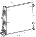
- zeigt perspektivisch einen Wärmeübertrager in Form eines Kühlmittel/Luftkühlers, an dessen auch als Sammelkästen bezeichneten Kühlmittelkästen eine Steckhatterung sowie eine Rastverbindung für die Festlegung eines zweiten Wärmeübertragers vorgesehen sind,shows in perspective a heat exchanger in the form of a coolant / air cooler, on its coolant boxes, also known as collection boxes a plug-in connector and a snap-in connection for the Definition of a second heat exchanger are provided,
- Fig. 2Fig. 2
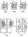
- in vergrößerter Darstellung einen Teil des einen Kühlmittelkastens des Kühlers nach Fig. 1 im Bereich einer als Loslager gestalteten Rastanordnung,in an enlarged view a part of a coolant box of the 1 in the area of a detent arrangement designed as a floating bearing,
- Fig. 3Fig. 3
-
eine weitere Rastanordnung an dem gegenüberliegenden Kühlemittelkasten
des Kühlers nach Fig. 1, die als Festlager gestattet ist, another locking arrangement on the
opposite coolant box 1, which is permitted as a fixed bearing, - Fig. 4Fig. 4
- schematisch einen Schnitt durch eine erfindungsgemäße Wärmeübertrageranordnung auf Höhe einer Rastanordnung nach Fig. 3, wobei an dem Kühler ein Kondensator festgelegt ist,schematically shows a section through a heat exchanger arrangement according to the invention 3, at the condenser is fixed to the cooler,
- Fig. 5a bis 5c5a to 5c
-
verschiedene Montageschritte der Funktion der Rastanordnungen
nach den Fig. 1 bis 4,different assembly steps of the function of the
locking arrangements 1 to 4, - Fig. 6Fig. 6
- schematisch eine weitere Ausführung einer Rastverbindung zur Festlegung eines ersten Wärmeübertragers an einen zweiten Wärmeübertrager,schematically another embodiment of a locking connection for fixing a first heat exchanger to a second heat exchanger,
- Fig. 7Fig. 7
- eine weitere Steckhalterung ähnlich Fig. 1 zur Festlegung der der Rastverbindung nach Fig. 6 gegenüberliegenden Seite des einen Wärmeübertragers an dem anderen Wärmeübertrager,another plug bracket similar to Fig. 1 for fixing the snap connection 6 opposite side of a heat exchanger on the other heat exchanger,
Ein Wärmeübertrager 1 in Form eines Kühlmittel/Luftkühlers ist in nachfolgend näher
beschriebener Weise mit einer Befestigungsvorrichtung versehen, die die Festlegung
eines zweiten Wärmeübertragers, vorzugsweise in Form eines Kondensators 1a (Fig. 4)
an dem Kühler 1 ermöglicht. Der Kühler 1 weist in an sich bekannter Weise einen Rippen/Rohrblock
2 auf, der in der Darstellung nach Fig. 1 im Bereich seiner Oberseite sowie
im Bereich seiner Unterseite durch nicht näher bezeichnete Seitenteile begrenzt ist.
Auf die gegenüberliegenden Seiten des Rippen/Rohrblockes 2 sind zwei Kühlmittelkästen
3, 4 aufgesetzt, die jeweils aus Kunststoff hergestellt sind. Zur Festlegung des Kondensators
1a an dem Kühler 1 wird der Kondensator 1a im Bereich einer unteren Befestigungsseite
in eine Steckhalterung 5, 6 am Kühler 1 eingesetzt, wobei die Steckhalterung
5, 6 durch zwei an den beiden Kühlmittelkästen 3, 4 angeformte, als hakenartige
Profilierungen dienende Stützhaken 5, 6 gestaltet ist. Die beiden Stützhaken 5, 6 nehmen
die Unterseite des Kondensators 1a derart auf, daß er formschlüssig nach unten
sowie horizontal vom Kühler 1 weg (auf Fig. 1 bezogen) gehalten ist. Der grundsätzliche
Aufbau sowie die Funktion der Steckhalterung 5, 6 entspricht der Steckhalterung, wie
sie in der DE 39 22 814 A1 beschrieben ist. Wesentlicher Unterschied ist bei der Steckhalterung
nach Fig. 1 wie auch nach Fig. 7, daß die Stützhaken 5, 6; 5a, 6a einstückig
an dem jeweiligen Kühlmittelkasten 3, 4; 3a, 4a angeformt sind. In geringem Abstand
oberhalb der Steckhalterung 5, 6 wie auch der Steckhalterung 5a, 6a sind ergänzende,
nicht näher bezeichnete Positionierstege vorgesehen, die eine spielfreie Halterung der
Unterseite des Kondensators in der Steckhalterung 5, 6; 5a, 6a im montierten Zustand
des Kondensators 1a am Kühler 1 gewährleisten.A
Zur Montage des Kondensators 1a im Bereich seines oberen Sammelkastens 3a an
dem Kühler 1 sind an der dem Kühler 1 zugewandten Seite der beiden Sammelkästen
3a zwei stabile Befestigungslaschen 14 festgelegt, wobei jeder Sammelkasten 3a mit
jeweils einer als Halteplatte dienende Befestigungslasche 14 versehen ist. Beim dargestellten
Ausführungsbeispiel ist der Sammelkasten 3a aus Metall hergestellt. Die Befestigungslaschen
14 sind mit den Sammelkästen 3a verlötet. Die beiden Befestigungslaschen
14 sind auf Höhe von beiden oberen Befestigungsstellen 7, 8 im Bereich der gegenüberliegenden
Kühlmittelkästen 3, 4 positioniert. Beide Befestigungslaschen 14
weisen gemäß den Fig. 2 und 3 jeweils eine, als rechteckiger Durchbruch gestaltete
Rastaussparung 11 auf, die mit beiden Rastanordnungen der Befestigungsstellen 7 und
8 in Wirkverbindung bringbar sind. Den beiden Rastanordnungen sind Kraftaufnahmeeinrichtungen
in Form von Stützkörpern 9 bzw. 9a (Fig. 2 und 3) zugeordnet, die jeweils
als quaderförmige Blöcke von den beiden Kühlmittelkästen 3, 4 abragen und einstückig
an diesen angeformt sind. Auch die nachfolgend näher beschriebenen Rastanordnungen
sind einstückig an den Kühlmittelkästen 3, 4 angeformt. Die Stützkörper 9, 9a sind
jeweils unmittelbar benachbart neben den zugeordneten Rastanordnungen angeordnet.
Die beiden Stützkörper 9, 9a der beiden Kraftaufnahmeeinrichtungen weisen eine Höhe
auf, die der Höhe der jeweiligen Rastaussparung 11 entspricht, so daß die oberen und
unteren Längsseiten der Rastaussparungen 11 die korrespondierenden oberen und unteren
Seitenflächen der quaderförmigen Stützkörper 9, 9a formschlüssig und stützend
flankieren.To mount the capacitor 1a in the area of its
Zur Schaffung der Loslagerfunktion der Befestigungsstelle 7 ist die Rastaussparung 11
in Querrichtung länger gestaltet als die gemeinsame Länge der Rastanordnung 10, 12
und des Stützkörpers 9, so daß die Befestigungslasche 14 relativ zu dem Stützkörper 9
und der Rastanordnung 10, 12 - auf die Darstellung nach den Fig. 1 bis 3 bezogen - horizontal
verschiebbar ist. Zur Schaffung der Festlagerfunktion bei der gegenüberliegenden
Befestigungsstelle 8 am anderen Kühlmittelkasten 4 ragen zwei Füllstege 13 zu
beiden Seiten von dem Stützkörper 9a einerseits und der Rastanordnung 10, 12 andererseits
nach außen ab, wobei beide Füllstege 13 jeweils einstückig am Kühlmittelkasten
4 angeformt sind. Die Füllstege 13 sind derart dimensioniert, daß die gesamte Breite
der Befestigungsstelle 8 etwa der korrespondierenden Länge der Rastaussparung 11
entspricht, so daß die Befestigungslasche 14 sowohl in Querrichtung als auch in Hochrichtung
im wesentlichen spielfrei durch den Stützkörper 9a sowie die Füllstege 13
gehalten ist.The
Sowohl auf der Loslager- als auch auf der Festlagerseite sind die Rastanordnungen jeweils
identisch gestaltet. Jede Rastanordnung weist ein Rasthakenpaar 10 auf, das in
Hochrichtung - auf die Darstellung nach den Fig. 1 bis 3 bezogen - in gewissen Grenzen
elastisch nachgiebig gestaltet ist. Beide Rasthaken des Rasthakenpaares 10 weisen
jeweils eine Rastnase auf, die nach oben bzw. nach unten ragt und im montierten
Zustand den oberen und den unteren Rand der zugeordneten Rastaussparung 11 der
Befestigungslasche 14 hintergreifen. Wie aus den Fig. 5a bis 5c gut erkennbar ist, ist
zwischen den beiden Rasthaken des Rasthakenpaares 10 ein als Anschlag und als
Stütze dienender Mittelsteg 12 vorgesehen, der an seinem freien Ende einen zu den
beiden Rasthaken 10 hin abragenden Hammerkopf aufweist. Dieser Mittelsteg 12 dient
dazu, die Auslenkung der Rasthaken 10 zur Mitte hin zu begrenzen und so eine zu
starke Biegung des einen oder des anderen Rasthakens 10 bei der Montage zu verhindern.
Der Mittelsteg 10 ist stabil und starr gestaltet und gewährleistet neben seiner Stützung
der Rasthaken 10 auch eine gleichmäßige und zentrierte Einführung der
Rasthaken 10 in die Rastaussparung 11, wie anhand der Fig. 5a bis 5c gut erkennbar
ist. Die Breite des Hammerkopfes des Mittelsteges 12 ist derart auf die Rasthaken 10
sowie deren zugehörige Rastnasen abgestimmt, daß die Rasthaken 10 beim Einschieben
der Rasthaken 10 in die Rastaussparung 11 gleichzeitig an dem Hammerkopf zur
Anlage kommen, wobei der Abstand der Spitzen der Rastnasen zueinander nahezu exakt
der korrespondierenden Erstreckung der Rastaussparung 11 entspricht. Da gleichzeitig
auch der jeweilige Stützkörper 9, 9a in die Rastaussparung eingefügt wird, ist eine
exakte Montierbarkeit gegeben, die fehlerhafte Montagen ausschließt. In der montierten
Position gemäß Fig. 5c hintergreifen die Rastnasen der Rasthaken 10 die Ränder der
Rastaussparung 11.The locking arrangements are on both the floating bearing and the fixed bearing side
designed identically. Each locking arrangement has a pair of
Das lediglich schematisch dargestellte Ausführungsbeispiel nach den Fig. 6 und 7 entspricht
im wesentlichen dem zuvor beschriebenen Ausführungsbeispiel nach den Fig. 1
bis 5c. Unterschiedlich bei diesem Ausführungsbeispiel ist die verbesserte Gestaltung
der beiden Rastanordnungen der als Loslager dienenden Befestigungsstelle 7a einerseits
und der als Festlager gestalteten Befestigungsstelle 8a andererseits. Den beiden
Rasthaken des Rasthakenpaares 10 sind jeweils quer zu den Rasthaken 10 elastisch
nachgiebige Stützzungen 19 zugeordnet, die Toleranzen der Rastverbindung ausgleichen
und einen spielfreien Sitz der Befestigungslaschen 14 auf den Rasthaken 10 ermöglichen.
Diese Stützzungen 19 werden aus ihrer unbelasteten Ruheposition gemäß
Fig. 6 beim Aufsetzen der Befestigungslaschen 14 nach unten gedrückt und verbleiben
in dieser vorgespannten Position, sobald die Rastnasen der Rasthaken 10 die Befestigungslasche
14 hintergreifen. Dadurch üben die Stützzungen 19 von unten her eine
Federkraft auf die Befestigungslaschen 14 aus, durch die diese gegen die Rastnasen
gedrückt werden. Dadurch wird eine spiel- und damit klapperfreie Befestigung erzielt.
Die Vorspannung der Stützzungen 19 ermöglicht zudem eine verbesserte Demontage
der Wärmeübertrager, da die Befestigungslaschen 14 nach dem Lösen der Rasthaken
durch die Stützzungen von den Rastanordnungen weggedrückt werden.The embodiment shown only schematically according to FIGS. 6 and 7 corresponds
essentially the previously described exemplary embodiment according to FIG. 1
to 5c. The improved design is different in this exemplary embodiment
of the two locking arrangements of the fastening point 7a serving as a floating bearing on the one hand
and the fastening point 8a designed as a fixed bearing on the other hand. The two
Latching hooks of the pair of latching hooks 10 are each elastic across the latching hooks 10
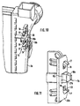
Beim Ausführungsbeispiel nach den Fig. 8 bis 11 sind die Rastanordnungen und die
Kraftaufnahmeeinrichtungen in nachfolgend näher beschriebener Weise voneinander
getrennt. Die untere Befestigung ist ebenfalls als Steckhalterung gestaltet, so daß hierzu
auf die Beschreibung zu den vorhergehenden Ausführungsbeispielen verwiesen
wird. Im Bereich der oberen Befestigungsseite weist der Wärmeübertrager, der vorzugsweise
ebenfalls als Kondensator gestaltet ist, zur Festlegung an den gegenüberliegenden
Kühlmittelkästen 4b für jede Befestigungsstelle 8b jeweils eine Befestigungslasche
20 auf, die starr an den Sammelkästen des Kondensators angeordnet sind. Die
beiden Befestigungslaschen 20 weisen zur Aufnahme von zwei zueinander beabstandeten
Rasthaken 17 zwei Rastaussparungen 22 auf. Zwischen den beiden Rastaussparungen
22 ist eine kreisrunde, als Stützausnehmung 21 dienende Aussparung in jeder
Befestigungslasche 20 vorgesehen, die zur spielfreien Aufnahme eines kegelartigen
Stützkörpers 15, 16 dient. Jedem Rasthaken 17 ist ein Stützsteg 18 zugeordnet, der einen
Anschlag für den jeweiligen Rasthaken 17 bildet, um ein zu starkes Umbiegen des
Rasthakens 17 bei der Montage zu verhindern. Der Stützsteg 18 ragt außerdem in die
korrespondierende Rastaussparung 22 hinein, wodurch sich ein zusätzlicher
Formschluß ergibt. Die Stützstege 18 sind starr und stabil gestaltet. Wie auch bei den
vorhergehenden Ausführungsbeispielen sind alle Elemente der Rastanordnungen sowie
der Kraftaufnahmeeinrichtungen einstückig an dem jeweiligen Kühlmittelkasten 4b angeformt.
Auch jedem Rasthaken 17 ist analog dem Ausführungsbeispiel nach Fig. 6 jeweils
eine elastisch nachgiebige Stützzunge 19 zugeordnet.In the embodiment of FIGS. 8 to 11, the locking arrangements and the
Force absorption devices in the manner described in more detail below
Cut. The lower attachment is also designed as a plug holder, so that this
reference is made to the description of the previous exemplary embodiments
becomes. In the area of the upper fastening side, the heat exchanger preferably has
is also designed as a capacitor for fixing to the opposite one
Der Stützkörper 15 weist eine Zentrierspitze 16 auf, die sich stark konisch verjüngt, um
eine vereinfachte Einführung des Stützkörpers 15 in die korrespondierende Stützausnehmung
21 bei der Montage der beiden Wärmeübertrager zu ermöglichen. The
Bei der die Loslagerseite definierenden Befestigungsstelle 7b nach den Fig. 10 und 11
sind die Rastanordnung einschließlich der Rasthaken 17, der Stützstege 18, der Stützzungen
19 sowie die Rastaussparungen 22 identisch gestaltet, so daß auf die vorherige
Beschreibung verwiesen wird.10 and 11 , the latching arrangement including the latching hooks 17, the
Bei dieser Loslagerseite ist der Stützkörper 15b jedoch als quaderartiger Füllkörper gestaltet,
der sich zu seinem freien Ende hin pyramidenstumpfartig verjüngt, wobei insbesondere
eine Zentrierspitze 16b Pyramidenstumpfform aufweist. Die korrespondierende
Stützausnehmung 21b ist rechteckig gestaltet und weist Abmessungen auf, die eine
Beweglichkeit der Befestigungslasche 20b in zwei Freiheitsgraden, beim dargestellten
Ausführungsbeispiel horizontal, ermöglichen. Auch die Rastaussparungen 22 sind in
entsprechender Weise breiter gestaltet, um die Horizontalbeweglichkeit im Bereich des
Stützkörpers 15b nicht zu blockieren.On this floating bearing side, however, the
Zur Festlegung des Kondensators an dem Kühler wird bei allen beschriebenen Ausführungsbeispielen der Kondensator zunächst schräg in die Steckhalterung eingesetzt und anschließend auch mit seiner Oberseite zum Kühler hin geschwenkt, wodurch die Rastanordnungen die Verrastung des Kondensators bewirken. Beim Hinschwenken des Kondensators zum Kühler hin erfolgt in gewissen Grenzen eine Kippung des unteren Bereiches des Kondensators im Bereich der Stützflansche oberhalb der Steckhalterung, wodurch die Unterseite des Kondensators nach außen gedrängt wird und an den Stützhaken der Steckhalterung zur Anlage kommt. Im montierten Zustand, d.h. im verrasteten Zustand des Kondensators steht somit die Unterseite des Kondensators im Bereich der Steckhalterung unter Spannung, wodurch die spielfreie Festlegung im Bereich der Steckhalterung erzielt wird.In all of the exemplary embodiments described, the capacitor is attached to the cooler the capacitor is inserted at an angle into the plug holder and then also pivoted with its upper side towards the radiator, causing the locking arrangements cause the capacitor to latch. When swiveling the The condenser to the cooler tilts the lower one within certain limits Area of the capacitor in the area of the support flanges above the plug holder, whereby the bottom of the capacitor is pushed outwards and on the support hook the plug holder comes into contact. In the assembled state, i.e. in the locked Condition of the capacitor is thus the bottom of the capacitor in the area the plug-in holder under tension, which means that there is no play in the area of the Plug bracket is achieved.
Claims (9)
- Heat exchanger arrangement with two heat exchangers (1, 1a), which are detachably connectable to one another by means of a mounting system at opposing mounting sides, wherein the mounting system has a push-in mounting of a hook-type shape on one mounting side and the mounting system on the other mounting side is a latch connection (7, 8; 7a, 8a; 7b, 8b), the push-in mounting (5, 6; 5a, 6a) and the latch connection being positioned in the region of oppositely lying collection tanks (3, 4; 3a, 4a; 4b) of the one heat exchanger,
characterised in that
the latch connection is split between a mounting point (7, 7a, 7b) provided in the form of a loose bearing and a mounting point (8, 8a, 8b) provided as a fixed bearing, each mounting point comprising a latch arrangement on one of the heat exchangers and at least one corresponding latch orifice (22) on the other heat exchanger, and each latch arrangement (10, 12; 17, 18, 19) is provided with a force-absorbing mechanism (9, 9a, 13; 15, 15b) having a respective supporting body (9, 9a; 15, 15b) and at least one supporting land (11; 21, 21b) on the other heat exchanger engaging at least partially around the supporting body when the heat exchangers are in the assembled state. - Heat exchanger arrangement as claimed in claim 1, characterised in that each latch arrangement has an elastically resilient latch hook pair (10, 17), the latch hooks of every latch hook pair (10, 17) latching round the edges of the corresponding latching orifice (22) in the assembled state.
- Heat exchanger arrangement as claimed in claim 2, characterised in that at least one supporting land (12, 18) is provided respectively between the latch hooks of every latch hook pair (10, 17) to limit displacement of the latch hooks (10, 17).
- Heat exchanger arrangement as claimed in claim 1, characterised in that the collecting tanks are made from a plastics material and the parts of the push-in mounting co-operating with the collecting tanks and the latch connection are integrally moulded on the collecting tanks.
- Heat exchanger arrangement as claimed in at least one of the preceding claims, characterised in that the latch arrangements (10, 12) and the associated force-absorbing mechanisms (9, 9a, 13) are positioned adjacent to one another and the edges of the latch orifices (11) are additionally designed to serve as supporting lands of the force-absorbing mechanisms.
- Heat exchanger arrangement as claimed in at least one of the preceding claims, characterised in that the supporting lands are provided in the form of edges of supporting orifices (21, 21b) and the latch orifices (22) and the supporting orifices (21, 21 b) are spaced at a distance apart from one another in a common retaining plate (20) for every latch arrangement.
- Heat exchanger arrangement as claimed in at least one of the preceding claims, characterised in that the supporting bodies (15, 15b) are provided with tapered centring tips (16, 16b).
- Heat exchanger arrangement as claimed in claim 7, characterised in that the supporting body (15) for the fixed bearing has a circular cross section and the supporting orifice (21) enclosing the supporting body is also circular.
- Heat exchanger arrangement as claimed in claim 8, characterised in that the supporting body (15b) for the loose bearing has a rectangular cross section and the corresponding supporting orifice (21b) likewise has a rectangular cross section, the sides of the supporting orifice (21b) running parallel with the axis linking fixed bearing and loose bearing being longer than the end surfaces of the supporting body (15b) which they flank.
Applications Claiming Priority (2)
| Application Number | Priority Date | Filing Date | Title |
|---|---|---|---|
| DE29712351U DE29712351U1 (en) | 1997-07-12 | 1997-07-12 | Heat exchanger arrangement with two heat exchangers |
| DE29712351U | 1997-07-12 |
Publications (3)
| Publication Number | Publication Date |
|---|---|
| EP0890811A2 EP0890811A2 (en) | 1999-01-13 |
| EP0890811A3 EP0890811A3 (en) | 1999-03-31 |
| EP0890811B1 true EP0890811B1 (en) | 2002-11-20 |
Family
ID=8043048
Family Applications (1)
| Application Number | Title | Priority Date | Filing Date |
|---|---|---|---|
| EP98111058A Expired - Lifetime EP0890811B1 (en) | 1997-07-12 | 1998-06-17 | Heat transfer apparatus with two heat exchangers |
Country Status (3)
| Country | Link |
|---|---|
| US (1) | US6158500A (en) |
| EP (1) | EP0890811B1 (en) |
| DE (2) | DE29712351U1 (en) |
Families Citing this family (79)
| Publication number | Priority date | Publication date | Assignee | Title |
|---|---|---|---|---|
| EP0825404B2 (en) | 1996-08-12 | 2008-04-16 | Calsonic Kansei Corporation | Integral-type heat exchanger |
| FR2772072B1 (en) * | 1997-12-10 | 2000-02-11 | Valeo Thermique Moteur Sa | DEVICE FOR FIXING A CONDUIT OF A FIRST HEAT EXCHANGER ON A FLUID BOX OF A SECOND HEAT EXCHANGER |
| FR2779220B1 (en) | 1998-05-28 | 2000-12-15 | Valeo Thermique Moteur Sa | HEAT EXCHANGER ASSEMBLY FOR A MOTOR VEHICLE |
| FR2785379B1 (en) | 1998-10-29 | 2001-06-15 | Valeo Thermique Moteur Sa | HEAT EXCHANGE MODULE COMPRISING A FAN NOZZLE AND A HEAT EXCHANGER, PARTICULARLY FOR A MOTOR VEHICLE |
| US20030009013A1 (en) * | 1998-12-30 | 2003-01-09 | Genentech, Inc. | Secreted and transmembrane polypeptides and nucleic acids encoding the same |
| DE19909672B4 (en) | 1999-03-05 | 2005-06-02 | Behr Gmbh & Co. Kg | cooling module |
| DE19909942A1 (en) * | 1999-03-06 | 2000-09-07 | Behr Gmbh & Co | Car engine space heat exchangers use fixer and receiver head to join exchangers in place assisted by fixer plate and snap-home straps for simple assembly. |
| FR2794170B1 (en) * | 1999-05-28 | 2001-06-29 | Renault | DEVICE FOR ATTACHING A FAN NOZZLE TO ELEMENTS OF THE COOLING UNIT OF AN INTERNAL COMBUSTION ENGINE OF A MOTOR VEHICLE |
| DE19930689B4 (en) * | 1999-07-02 | 2004-11-25 | Behr Gmbh & Co. Kg | Heat exchanger with holder |
| FR2800030B1 (en) * | 1999-10-25 | 2002-01-11 | Plastic Omnium Cie | AUTOMOTIVE VEHICLE STRUCTURE PART, ESPECIALLY FRONT OF TECHNICAL FRONT |
| DE19953787B4 (en) * | 1999-11-09 | 2005-12-15 | Behr Gmbh & Co. Kg | Arrangement for connecting two heat exchangers |
| DE10002745A1 (en) * | 2000-01-22 | 2001-07-26 | Modine Mfg Co | Device for connecting two heat exchangers |
| FR2808870A1 (en) * | 2000-05-12 | 2001-11-16 | Ecia Equip Composants Ind Auto | Heat exchanger with air flow guide in motor vehicle, uses air guide plate clipped onto one end of radiator in hinge structure to allow plate to then be closed over radiator and held closed by clip fastenings |
| US6273182B1 (en) * | 2000-05-19 | 2001-08-14 | Delphi Technologies, Inc. | Heat exchanger mounting |
| JP4505955B2 (en) * | 2000-06-20 | 2010-07-21 | 株式会社デンソー | Blower mounting structure |
| FR2814230B1 (en) * | 2000-09-20 | 2002-12-13 | Valeo Thermique Moteur Sa | HEAT EXCHANGE MODULE FOR MOTOR VEHICLE |
| JP4508499B2 (en) * | 2001-09-28 | 2010-07-21 | 三菱重工業株式会社 | Mounting structure |
| US7287574B2 (en) * | 2002-02-11 | 2007-10-30 | Valeo, Inc. | Attachment and articles using same |
| DE10207025A1 (en) * | 2002-02-20 | 2003-08-28 | Behr Gmbh & Co | Mounting for vehicle radiator comprises clip at top and pivot at bottom |
| US6793012B2 (en) | 2002-05-07 | 2004-09-21 | Valeo, Inc | Heat exchanger |
| DE10250334A1 (en) * | 2002-10-29 | 2004-05-19 | Modine Manufacturing Co., Racine | Heat exchanger arrangement for motor vehicles |
| US7337832B2 (en) * | 2003-04-30 | 2008-03-04 | Valeo, Inc. | Heat exchanger |
| US6904963B2 (en) * | 2003-06-25 | 2005-06-14 | Valeo, Inc. | Heat exchanger |
| US7527087B2 (en) * | 2003-06-30 | 2009-05-05 | Valeo, Inc. | Heat exchanger |
| US20050008428A1 (en) * | 2003-07-09 | 2005-01-13 | Valeo Inc | Attachment and articles using same |
| US7059392B2 (en) * | 2003-07-11 | 2006-06-13 | Newfrey Llc | Radiator attachment assemblies, apparatus components, and methods |
| DE10333381B4 (en) | 2003-07-23 | 2005-10-27 | A. Raymond & Cie | Device for attaching an attachment adapter to a radiator |
| DE10340566A1 (en) * | 2003-09-01 | 2005-03-31 | Behr Gmbh & Co. Kg | Mounting arrangement of the device for exchanging heat |
| DE10348701A1 (en) * | 2003-10-16 | 2005-05-12 | Behr Gmbh & Co Kg | Arrangement for fixing a heat exchanger to another |
| DE10349139A1 (en) * | 2003-10-17 | 2005-05-12 | Behr Gmbh & Co Kg | Arrangement for fastening a fan cowl |
| DE102004058724B4 (en) * | 2003-12-09 | 2018-11-15 | Denso Corporation | Heat exchanger and cooling module with this |
| DE102005004521A1 (en) * | 2004-01-29 | 2005-08-18 | Behr Gmbh & Co. Kg | Assembly of heat exchangers mounted against each other, e.g. for a vehicle air conditioning system, has holders at the corners of one exchanger to grip around the other for its support |
| JP4281634B2 (en) * | 2004-06-28 | 2009-06-17 | 株式会社デンソー | Refrigerant evaporator |
| US7775265B2 (en) * | 2004-09-15 | 2010-08-17 | Flex-A-Lite Consolidated, Inc. | Side tank design |
| US7175142B2 (en) * | 2004-10-21 | 2007-02-13 | Custom Molders, Inc. | Transmission oil cooler bracket |
| US20060113068A1 (en) * | 2004-11-30 | 2006-06-01 | Valeo, Inc. | Multi fluid heat exchanger assembly |
| DE102005002058A1 (en) * | 2005-01-14 | 2006-09-14 | Behr Gmbh & Co. Kg | Heat exchanger |
| EP1686341B1 (en) * | 2005-01-28 | 2008-01-23 | DENSO THERMAL SYSTEMS S.p.A. | Cooling assembly for vehicles |
| DE602005008723D1 (en) * | 2005-05-27 | 2008-09-18 | Denso Thermal Systems Spa | Heat exchanger arrangement for motor vehicles |
| DE102005039090A1 (en) * | 2005-08-06 | 2007-02-08 | Behr Gmbh & Co. Kg | Assembly support system |
| DE102005040607A1 (en) * | 2005-08-27 | 2007-03-15 | Behr Gmbh & Co. Kg | Arrangement for fixing a heat exchanger to another |
| US20070044953A1 (en) * | 2005-08-31 | 2007-03-01 | Valeo, Inc. | Heat exchanger |
| DE102005043937B4 (en) * | 2005-09-15 | 2007-11-08 | Hbpo Gmbh | Fastening and connecting element for heat exchangers and arrangement of heat exchangers in a motor vehicle |
| JP4779641B2 (en) * | 2005-12-26 | 2011-09-28 | 株式会社デンソー | Combined heat exchanger |
| US20070199685A1 (en) * | 2006-02-28 | 2007-08-30 | Valeo, Inc. | Two-fold combo-cooler |
| JP4830700B2 (en) * | 2006-04-21 | 2011-12-07 | 株式会社デンソー | Cooling module |
| DE102007006241B4 (en) | 2007-02-08 | 2022-08-25 | Mahle International Gmbh | Fastening arrangement for heat exchangers |
| KR101291207B1 (en) * | 2007-02-26 | 2013-07-31 | 삼성전자주식회사 | Refrigerator and Evaporator mounting structure for refrigerator |
| EP2110632B1 (en) * | 2008-04-14 | 2015-12-02 | MAHLE Behr Spain S.A. | Heat exchanger, in particular charged air cooler, with a latchable fixing device |
| FR2929386B1 (en) * | 2008-04-29 | 2014-10-24 | Valeo Systemes Thermiques | HEAT EXCHANGE MODULE HAVING ASSEMBLY MEANS, IN PARTICULAR FOR MOTOR VEHICLES |
| EP2146169B1 (en) * | 2008-07-15 | 2018-02-21 | MAHLE Behr GmbH & Co. KG | Device for attaching a coolant condenser to a coolant cooler |
| FR2935643B1 (en) * | 2008-09-09 | 2013-05-10 | Renault Sas | AIR CONDITIONER AND HOUSING SUITABLE TO ATTACH TO THIS AIR CONDITIONER |
| EP2280238B1 (en) * | 2009-07-28 | 2016-07-27 | MAHLE Behr Spain S.A. | Cooling module |
| DE102009043794B4 (en) | 2009-09-30 | 2022-07-07 | Valeo Gmbh | Repair element for replacing a broken mounting pin of a vehicle cooling module, vehicle cooling module and their combination |
| DE102010029698A1 (en) * | 2010-06-04 | 2011-12-08 | Behr Gmbh & Co. Kg | Coolant radiator |
| DE102010039311A1 (en) * | 2010-08-13 | 2012-02-16 | Behr Gmbh & Co. Kg | Arrangement for connecting a heat exchanger with another component |
| FR2979424B1 (en) * | 2011-08-22 | 2013-10-25 | Renault Sa | COOLING MODULE OF A MOTOR VEHICLE |
| FR2979857B1 (en) * | 2011-09-13 | 2013-11-22 | Renault Sa | COOLING ARRANGEMENT FOR A MOTOR VEHICLE |
| DE102011084307A1 (en) * | 2011-10-11 | 2013-04-11 | Behr Gmbh & Co. Kg | Radiator device and method for manufacturing a radiator device for a vehicle |
| JP5660024B2 (en) * | 2011-12-27 | 2015-01-28 | 株式会社デンソー | Heat exchanger assembly structure |
| DE102012202889A1 (en) * | 2012-02-24 | 2013-08-29 | Behr Gmbh & Co. Kg | Arrangement for fastening of heat exchangers i.e. cooling modules, of motor car, has receiving module for receiving insert element, and mounting element assigned with trim of motor car for assembly of heat exchanger |
| DE102013202146A1 (en) * | 2013-02-08 | 2014-08-14 | Behr Gmbh & Co. Kg | Radiator device i.e. cooling module, for vehicle e.g. passenger car, has snap connections whose elements are formed such that connections are generated between components, and input generated between components over one of connections |
| DE102014201991A1 (en) * | 2013-02-16 | 2014-08-21 | Volkswagen Aktiengesellschaft | Cooling device for a motor vehicle |
| JP6048231B2 (en) * | 2013-03-11 | 2016-12-21 | マツダ株式会社 | Radiator support device for vehicle |
| JP6272121B2 (en) * | 2014-04-21 | 2018-01-31 | 三菱電機株式会社 | Air conditioner |
| KR101764579B1 (en) * | 2014-09-01 | 2017-08-23 | 한온시스템 주식회사 | Radiator and condenser assembly |
| US10048023B2 (en) * | 2015-08-27 | 2018-08-14 | Denso International America, Inc. | Heat exchanger shroud mount |
| FR3047553B1 (en) * | 2016-02-05 | 2019-05-17 | Valeo Systemes Thermiques | ASSEMBLY DEVICE BETWEEN A HEAT EXCHANGER OF AN AIR CONDITIONING INSTALLATION AND A COOLING RADIATOR OF THE ENGINE OF A MOTOR VEHICLE. |
| EP3290848B1 (en) | 2016-09-02 | 2020-05-06 | Modine Manufacturing Company | Header for a heat exchanger, and method of making the same |
| USD921043S1 (en) * | 2018-09-12 | 2021-06-01 | Resource International Inc. | Radiator for automotive applications |
| USD912702S1 (en) * | 2018-09-12 | 2021-03-09 | Resource International Inc. | Radiator for automotive applications |
| USD905759S1 (en) * | 2018-09-27 | 2020-12-22 | Resource International Inc. | Radiator for automotive applications |
| USD891318S1 (en) * | 2018-10-24 | 2020-07-28 | Specialty Auto Parts U.S.A., Inc. | Coolant radiator core |
| DE102019200340A1 (en) | 2019-01-14 | 2020-07-16 | Mahle International Gmbh | Component and floating bearing device |
| US11320215B2 (en) | 2019-06-24 | 2022-05-03 | Denso International America, Inc. | Radiator including thermal stress countermeasure |
| USD913335S1 (en) * | 2019-07-26 | 2021-03-16 | Resource International Inc. | Radiator for automotive applications |
| US20220288995A1 (en) * | 2021-03-09 | 2022-09-15 | Denso International America, Inc. | Snap-fit attachment repair |
| DE102021204988A1 (en) * | 2021-05-18 | 2022-11-24 | Volkswagen Aktiengesellschaft | Connection system for connecting two heat exchangers, heat exchanger, heat exchanger arrangement and motor vehicle |
| FR3123115B1 (en) * | 2021-05-20 | 2023-12-22 | Valeo Systemes Thermiques | Thermal module for automobile vehicles. |
Family Cites Families (16)
| Publication number | Priority date | Publication date | Assignee | Title |
|---|---|---|---|---|
| CH67832A (en) * | 1913-11-22 | 1915-01-16 | Adolph Saurer | Suspension device for automobile radiators |
| DE3536457A1 (en) * | 1985-10-12 | 1987-06-25 | Sueddeutsche Kuehler Behr | HEAT EXCHANGER, ESPECIALLY RADIATOR FOR MOTOR VEHICLES |
| DE3744644A1 (en) * | 1987-12-31 | 1989-07-13 | Sueddeutsche Kuehler Behr | Device for fastening a fan cowl to the waterbox of an air/water radiator for motor vehicles |
| DE3922814A1 (en) * | 1988-09-30 | 1990-04-12 | Piemontese Radiatori | Mounting frame for motor vehicle radiator - has slide mounting cooling block and fittings for condenser and oil cooler |
| DE3907926A1 (en) * | 1989-03-11 | 1990-09-13 | Sueddeutsche Kuehler Behr | Heat exchanger, in particular a radiator for commercial (utility) vehicles |
| DE3918176A1 (en) * | 1989-06-03 | 1990-12-06 | Behr Gmbh & Co | HEAT EXCHANGER FOR COOLING THE COOLING WATER AND CHARGING AIR OF AN INTERNAL COMBUSTION ENGINE |
| DE4109284A1 (en) * | 1991-03-21 | 1992-09-24 | Behr Gmbh & Co | WATER / AIR COOLER FOR WATER-COOLED COMBUSTION ENGINES |
| DE4137038C1 (en) * | 1991-11-11 | 1993-06-03 | Thermal-Werke, Waerme-, Kaelte-, Klimatechnik Gmbh, 6832 Hockenheim, De | Radiator case for front body of motor vehicle - has distance pieces, one elastic, to clamp flat tube heat exchanger between frame and collectors |
| US5139080A (en) * | 1991-12-16 | 1992-08-18 | General Motors Corporation | Mounting assembly for an automotive condenser |
| DE4225253C2 (en) * | 1992-08-03 | 1996-12-05 | Behr Gmbh & Co | Arrangement of a plastic water tank and an expansion tank made of plastic |
| DE9319025U1 (en) * | 1993-12-11 | 1994-02-03 | Behr Gmbh & Co | Heat exchanger with fan cover |
| DE4421835A1 (en) * | 1994-06-22 | 1996-01-04 | Behr Gmbh & Co | Heat exchangers, in particular coolers for internal combustion engines of commercial vehicles |
| DE4425350A1 (en) * | 1994-07-18 | 1996-01-25 | Behr Gmbh & Co | Arrangement for connecting two or more heat exchangers |
| FR2739598B1 (en) * | 1995-10-06 | 1997-12-05 | Valeo Thermique Moteur Sa | DEVICE FOR ATTACHING A HIGH TEMPERATURE HEAT EXCHANGER |
| ES2142674T3 (en) * | 1996-05-04 | 2000-04-16 | Ford Motor Co | RADIATOR AND CONDENSER ASSEMBLY. |
| DE29707571U1 (en) * | 1997-04-26 | 1997-07-10 | Laengerer & Reich Gmbh & Co | Arrangement for connecting two heat exchangers |
-
1997
- 1997-07-12 DE DE29712351U patent/DE29712351U1/en not_active Expired - Lifetime
-
1998
- 1998-06-17 DE DE59806318T patent/DE59806318D1/en not_active Expired - Lifetime
- 1998-06-17 EP EP98111058A patent/EP0890811B1/en not_active Expired - Lifetime
- 1998-07-09 US US09/112,145 patent/US6158500A/en not_active Expired - Lifetime
Also Published As
| Publication number | Publication date |
|---|---|
| DE29712351U1 (en) | 1997-09-11 |
| DE59806318D1 (en) | 2003-01-02 |
| US6158500A (en) | 2000-12-12 |
| EP0890811A2 (en) | 1999-01-13 |
| EP0890811A3 (en) | 1999-03-31 |
Similar Documents
| Publication | Publication Date | Title |
|---|---|---|
| EP0890811B1 (en) | Heat transfer apparatus with two heat exchangers | |
| EP0017940B1 (en) | Electrical connecting assembly | |
| DE3423235C2 (en) | Fastening device | |
| EP1214232B1 (en) | Connecting piece for connecting a wiper blade to a wiper arm | |
| EP0170952B1 (en) | Water/air radiator for a water-cooled combustion engine | |
| DE2914317C2 (en) | Connector device | |
| DE4142023C2 (en) | Heat exchanger unit for motor vehicles | |
| EP2883284B1 (en) | Connection module | |
| EP2789931A1 (en) | Holding apparatus for fixing a surface module to a support | |
| EP1478539A1 (en) | Assembly support of a front end of a motor vehicle and method for detachably fixing a cooling module to an assembly support of a front end | |
| DE19941499A1 (en) | Connector for connecting a wiper blade to a wiper arm | |
| DE8412114U1 (en) | Spacer for mounting plates | |
| DE3331207A1 (en) | Assembly for electronic controllers | |
| EP1958811A2 (en) | Protection device for the heat exchanger of a motor vehicle | |
| EP0346602A1 (en) | Water/air cooler for water-cooled internal-combustion engines, especially those of commercial vehicles | |
| DE3907926A1 (en) | Heat exchanger, in particular a radiator for commercial (utility) vehicles | |
| DE102017112548B4 (en) | ELECTRICAL CONTACT DEVICE AND METALLIC RECORDING FOR AN ELECTRICAL CONTACT DEVICE | |
| DE102006041803B4 (en) | Device for attaching a device to a mounting rail | |
| EP0148334A2 (en) | Device for the attachment of accessories on the wall of a lighting fixture | |
| EP2223843B1 (en) | Front end module for vehicles | |
| EP0705735B1 (en) | Support device for casings, in particular for casings of electronic devices in industrial vehicles | |
| DE102020208118B4 (en) | PCB mount, method, system and use | |
| EP0974854B1 (en) | Optical module for an optical plug connection | |
| DE3844310C2 (en) | ||
| DE2255185C3 (en) | Fastening element for electrical connection units |
Legal Events
| Date | Code | Title | Description |
|---|---|---|---|
| PUAI | Public reference made under article 153(3) epc to a published international application that has entered the european phase |
Free format text: ORIGINAL CODE: 0009012 |
|
| AK | Designated contracting states |
Kind code of ref document: A2 Designated state(s): DE FR GB IT |
|
| AX | Request for extension of the european patent |
Free format text: AL;LT;LV;MK;RO;SI |
|
| PUAL | Search report despatched |
Free format text: ORIGINAL CODE: 0009013 |
|
| AK | Designated contracting states |
Kind code of ref document: A3 Designated state(s): AT BE CH CY DE DK ES FI FR GB GR IE IT LI LU MC NL PT SE |
|
| AX | Request for extension of the european patent |
Free format text: AL;LT;LV;MK;RO;SI |
|
| 17P | Request for examination filed |
Effective date: 19990715 |
|
| AKX | Designation fees paid |
Free format text: DE FR GB IT |
|
| 17Q | First examination report despatched |
Effective date: 20000616 |
|
| GRAG | Despatch of communication of intention to grant |
Free format text: ORIGINAL CODE: EPIDOS AGRA |
|
| GRAG | Despatch of communication of intention to grant |
Free format text: ORIGINAL CODE: EPIDOS AGRA |
|
| GRAH | Despatch of communication of intention to grant a patent |
Free format text: ORIGINAL CODE: EPIDOS IGRA |
|
| GRAH | Despatch of communication of intention to grant a patent |
Free format text: ORIGINAL CODE: EPIDOS IGRA |
|
| GRAA | (expected) grant |
Free format text: ORIGINAL CODE: 0009210 |
|
| AK | Designated contracting states |
Kind code of ref document: B1 Designated state(s): DE FR GB IT |
|
| REG | Reference to a national code |
Ref country code: GB Ref legal event code: FG4D Free format text: NOT ENGLISH |
|
| REF | Corresponds to: |
Ref document number: 59806318 Country of ref document: DE Date of ref document: 20030102 |
|
| GBT | Gb: translation of ep patent filed (gb section 77(6)(a)/1977) |
Effective date: 20030127 |
|
| ET | Fr: translation filed | ||
| PLBQ | Unpublished change to opponent data |
Free format text: ORIGINAL CODE: EPIDOS OPPO |
|
| PLBI | Opposition filed |
Free format text: ORIGINAL CODE: 0009260 |
|
| PLAX | Notice of opposition and request to file observation + time limit sent |
Free format text: ORIGINAL CODE: EPIDOSNOBS2 |
|
| 26 | Opposition filed |
Opponent name: VALEO THERMIQUE MOTEUR S.A. Effective date: 20030820 |
|
| PLAX | Notice of opposition and request to file observation + time limit sent |
Free format text: ORIGINAL CODE: EPIDOSNOBS2 |
|
| PLBB | Reply of patent proprietor to notice(s) of opposition received |
Free format text: ORIGINAL CODE: EPIDOSNOBS3 |
|
| RAP2 | Party data changed (patent owner data changed or rights of a patent transferred) |
Owner name: BEHR GMBH & CO. KG |
|
| PLCK | Communication despatched that opposition was rejected |
Free format text: ORIGINAL CODE: EPIDOSNREJ1 |
|
| APAH | Appeal reference modified |
Free format text: ORIGINAL CODE: EPIDOSCREFNO |
|
| APBP | Date of receipt of notice of appeal recorded |
Free format text: ORIGINAL CODE: EPIDOSNNOA2O |
|
| APAH | Appeal reference modified |
Free format text: ORIGINAL CODE: EPIDOSCREFNO |
|
| APBQ | Date of receipt of statement of grounds of appeal recorded |
Free format text: ORIGINAL CODE: EPIDOSNNOA3O |
|
| APBU | Appeal procedure closed |
Free format text: ORIGINAL CODE: EPIDOSNNOA9O |
|
| PLBN | Opposition rejected |
Free format text: ORIGINAL CODE: 0009273 |
|
| STAA | Information on the status of an ep patent application or granted ep patent |
Free format text: STATUS: OPPOSITION REJECTED |
|
| 27O | Opposition rejected |
Effective date: 20071214 |
|
| PLAB | Opposition data, opponent's data or that of the opponent's representative modified |
Free format text: ORIGINAL CODE: 0009299OPPO |
|
| PGFP | Annual fee paid to national office [announced via postgrant information from national office to epo] |
Ref country code: IT Payment date: 20100630 Year of fee payment: 13 Ref country code: GB Payment date: 20100621 Year of fee payment: 13 Ref country code: FR Payment date: 20100722 Year of fee payment: 13 Ref country code: DE Payment date: 20100623 Year of fee payment: 13 |
|
| GBPC | Gb: european patent ceased through non-payment of renewal fee |
Effective date: 20110617 |
|
| PG25 | Lapsed in a contracting state [announced via postgrant information from national office to epo] |
Ref country code: IT Free format text: LAPSE BECAUSE OF NON-PAYMENT OF DUE FEES Effective date: 20110617 |
|
| REG | Reference to a national code |
Ref country code: FR Ref legal event code: ST Effective date: 20120229 |
|
| REG | Reference to a national code |
Ref country code: DE Ref legal event code: R119 Ref document number: 59806318 Country of ref document: DE Effective date: 20120103 |
|
| PG25 | Lapsed in a contracting state [announced via postgrant information from national office to epo] |
Ref country code: FR Free format text: LAPSE BECAUSE OF NON-PAYMENT OF DUE FEES Effective date: 20110630 Ref country code: DE Free format text: LAPSE BECAUSE OF NON-PAYMENT OF DUE FEES Effective date: 20120103 |
|
| PG25 | Lapsed in a contracting state [announced via postgrant information from national office to epo] |
Ref country code: GB Free format text: LAPSE BECAUSE OF NON-PAYMENT OF DUE FEES Effective date: 20110617 |