EP0890726B1 - Vierventil-Blockzylinderkopf mit schräg angeordneten Gaswechselventilen - Google Patents
Vierventil-Blockzylinderkopf mit schräg angeordneten Gaswechselventilen Download PDFInfo
- Publication number
- EP0890726B1 EP0890726B1 EP98110044A EP98110044A EP0890726B1 EP 0890726 B1 EP0890726 B1 EP 0890726B1 EP 98110044 A EP98110044 A EP 98110044A EP 98110044 A EP98110044 A EP 98110044A EP 0890726 B1 EP0890726 B1 EP 0890726B1
- Authority
- EP
- European Patent Office
- Prior art keywords
- cylinder head
- bearing frame
- cylinder
- camshaft bearing
- camshaft
- Prior art date
- Legal status (The legal status is an assumption and is not a legal conclusion. Google has not performed a legal analysis and makes no representation as to the accuracy of the status listed.)
- Expired - Lifetime
Links
Images


Classifications
-
- F—MECHANICAL ENGINEERING; LIGHTING; HEATING; WEAPONS; BLASTING
- F02—COMBUSTION ENGINES; HOT-GAS OR COMBUSTION-PRODUCT ENGINE PLANTS
- F02B—INTERNAL-COMBUSTION PISTON ENGINES; COMBUSTION ENGINES IN GENERAL
- F02B3/00—Engines characterised by air compression and subsequent fuel addition
- F02B3/06—Engines characterised by air compression and subsequent fuel addition with compression ignition
-
- F—MECHANICAL ENGINEERING; LIGHTING; HEATING; WEAPONS; BLASTING
- F02—COMBUSTION ENGINES; HOT-GAS OR COMBUSTION-PRODUCT ENGINE PLANTS
- F02F—CYLINDERS, PISTONS OR CASINGS, FOR COMBUSTION ENGINES; ARRANGEMENTS OF SEALINGS IN COMBUSTION ENGINES
- F02F1/00—Cylinders; Cylinder heads
- F02F1/24—Cylinder heads
- F02F1/42—Shape or arrangement of intake or exhaust channels in cylinder heads
- F02F1/4214—Shape or arrangement of intake or exhaust channels in cylinder heads specially adapted for four or more valves per cylinder
-
- F—MECHANICAL ENGINEERING; LIGHTING; HEATING; WEAPONS; BLASTING
- F02—COMBUSTION ENGINES; HOT-GAS OR COMBUSTION-PRODUCT ENGINE PLANTS
- F02B—INTERNAL-COMBUSTION PISTON ENGINES; COMBUSTION ENGINES IN GENERAL
- F02B2275/00—Other engines, components or details, not provided for in other groups of this subclass
- F02B2275/18—DOHC [Double overhead camshaft]
-
- F—MECHANICAL ENGINEERING; LIGHTING; HEATING; WEAPONS; BLASTING
- F02—COMBUSTION ENGINES; HOT-GAS OR COMBUSTION-PRODUCT ENGINE PLANTS
- F02F—CYLINDERS, PISTONS OR CASINGS, FOR COMBUSTION ENGINES; ARRANGEMENTS OF SEALINGS IN COMBUSTION ENGINES
- F02F1/00—Cylinders; Cylinder heads
- F02F1/24—Cylinder heads
- F02F2001/244—Arrangement of valve stems in cylinder heads
- F02F2001/245—Arrangement of valve stems in cylinder heads the valve stems being orientated at an angle with the cylinder axis
-
- Y—GENERAL TAGGING OF NEW TECHNOLOGICAL DEVELOPMENTS; GENERAL TAGGING OF CROSS-SECTIONAL TECHNOLOGIES SPANNING OVER SEVERAL SECTIONS OF THE IPC; TECHNICAL SUBJECTS COVERED BY FORMER USPC CROSS-REFERENCE ART COLLECTIONS [XRACs] AND DIGESTS
- Y02—TECHNOLOGIES OR APPLICATIONS FOR MITIGATION OR ADAPTATION AGAINST CLIMATE CHANGE
- Y02T—CLIMATE CHANGE MITIGATION TECHNOLOGIES RELATED TO TRANSPORTATION
- Y02T10/00—Road transport of goods or passengers
- Y02T10/10—Internal combustion engine [ICE] based vehicles
- Y02T10/12—Improving ICE efficiencies
Definitions
- the invention relates to a self-igniting internal combustion engine with a cylinder head, which continues to have a crankcase and one inside having rotatably mounted crankshaft, each with a piston connected connecting rods are articulated, wherein the piston in one covered by the cylinder head cylinder to form a Brennraums is movable, wherein in the region of the cylinder head two Camshafts are arranged, each cylinder gas exchange valves, in particular control two intake valves and two exhaust valves, wherein the intake valves and the Austassventile with the valve stems arranged inclined to the cylinder head longitudinal side walls outwardly are, furthermore, an injection valve in a central recess can be used as the lubricating oil leading and / or coolant Spaces separated area is formed, and itself the recess from the combustion chamber at least up to the height of the camshaft axes extends
- Such a cylinder head is known from EP 0 780 560 A1.
- the axes of the valve stems are not the axes of the two aligned overhead camshafts, so that extra Drag lever to overcome the resulting offset between used the camshafts and the gas exchange valves Need to become.
- the cylinder head bolts are at least partially arranged so that they are exactly in the area below cams of the Camshaft lie. This is given that the camshaft frame after mounting the cylinder head on the crankcase must be mounted.
- DE 43 23 073 A1 is another Internal combustion engine with a cylinder head known in the also two overhead camshafts stored in the cylinder head are.
- camshafts of a camshaft bearing frame attached to the cylinder head wherein the camshaft bearing frame simultaneously has a cover function and the underlying covering oil-bearing cylinder head space to the environment. Also at In this internal combustion engine, the valve axes are not the cams The camshaft aligned, so that here also cam follower mounted Need to become.
- the camshaft bearing frame may be design-related only after the assembly of the cylinder head on the crankcase the internal combustion engine are mounted.
- GB 2164703 A also a cylinder head for an internal combustion engine known.
- the cylinder head two overhead camshafts, by means of individual bearing blocks are attached to the cylinder head.
- the peculiarity of Camshaft is located in the area of the cylinder head bolts Have recesses, which are dimensioned so that the cylinder head bolts are used with the camshafts installed and can be screwed.
- the invention has for its object to provide a cylinder head, designed as a block cylinder head so that a reliable Separation of lubricating oil-carrying or coolant-carrying Spaces across areas are secured in the fuel can get.
- the cylinder head (the block cylinder head is for language simplification always called cylinder head) one through the camshaft axes extending parting plane, to which a camshaft bearing frame connects, with the camshafts between the cylinder head and camshaft bearing frames are mounted.
- the recess extends as a separate area through the camshaft bearing frame through and opens into a mounting room in the upper Camshaft bearing frame.
- the injection valve and the Glow pin per cylinder
- the recess and the second recess lead to a common assembly room, which is located in the upper area of the camshaft bearing frame is arranged and extends along the cylinder head.
- the division of the cylinder head into a cylinder head and a camshaft bearing frame makes sense for several reasons.
- the division of the mold of the Cylinder head easier.
- the cylinder head and the Camshaft bearing frames made of different materials be, with the cylinder head in particular of gray cast iron or a higher quality alloy and the camshaft bearing frame are cast from a standard light metal alloy. This results in weight advantages.
- the separation between cylinder head and camshaft bearing frames in the area of the camshaft axes offers the advantage that overall the assembly of the individual Components is simplified. So the cylinder head can be simpler Way to be fitted with inlet and outlet valves and In addition, acting directly on the valve stems hydraulic tappets in appropriately machined holes are used.
- the camshafts are inserted and fixed by mounting the camshaft bearing frame.
- the seal the camshaft bearing frame relative to the cylinder head carried out by rubber-form seals and / or O-rings, in the Dichtnut Schemee the camshaft bearing frame and / or Cylinder head can be used. This is a reliable seal ensures that even after dismantling with the existing Rubber molded gaskets and / or O-rings again is safe to seal.
- the camshafts are so to the cylinder head bolts arranged that with inserted camshafts and screwed camshaft bearing frame the cylinder head screw heads are accessible in the form that the cam shafts Have flats in the area of the camshaft bolts.
- the cylinder head and the camshaft bearing frame pre-assembled as a complete unit and then this assembly on the crankcase of the Internal combustion engine is placed and by means of cylinder head bolts is attached.
- the camshafts are in this context consciously in the assembly area of the cylinder head bolts been laid down that these by flattening in the field of Camshaft shafts can be mounted.
- the inlet gas exchange valve channels a joint formed at the obtuse angle to the parting plane Mouth surface, to which an air intake line can be connected is. This allows the cores of the intake changeover valve channels simply be fixed in the mold and the casting cores be easily removed after the casting process.
- the inlet channels of a cylinder are a swirl channel and a tangential channel formed while the two exhaust valves are combined to a trouser channel and in the right Open the angle to the cylinder head surface in the cylinder head longitudinal surface.
- This design allows a clear separation of the intake ports and outlet channels, in particular the thermally highly loaded Outlet channels on a short path from the combustion chamber to the cylinder head longitudinal surface are guided.
- the tangential channel and the swirl channel a cylinder are guided so that the tangential of a Cylinder lateral (meaning the sides between and at the end of the Cylinder transverse to the cylinder longitudinal axis) over the cylinder center the second cylinder side is guided, while the associated swirl duct behind a cylinder head screw whistle forth from the second Cylinder side to the first cylinder side of the adjacent cylinder is guided.
- camshaft bearing frame The entire cylinder head with the camshaft bearing frame is so in the most extensive version completely mountable and on the crankcase placed. On the other hand, the camshaft bearing frame but also, for example, for repairs alone disassembled.
- the camshafts with bearing bridges on appropriately designed storage chairs in to fix the camshaft bearing frame are then placed completely on the cylinder head and this is mounted on the crankcase.
- an opening in Height of the injector high-pressure connection opens, which itself extends to a side wall of the camshaft bearing frame.
- the Recess and / or the second recess can be a lateral Have disposal opening. This disposal opening is advantageous at geodetically lower point, in particular the Zweitaus Principleung arranged in the cylinder head.
- the camshaft bearing frame is advantageous the cover of an air intake pipe.
- the air intake pipe preferably formed in the lower part by the cylinder head and in the described upper area through the camshaft bearing frame. This is also for this functional part of Manufacturing and assembly costs minimized.
- the camshaft bearing frame and / or cylinder head can provide a calming room for Be integrated with blow-by gases. In this calming room, the Oil components of the blow-by gas largely excreted and fed back to the oil circuit of the internal combustion engine.
- the end face of the camshaft bearing frame a toothed space formed in which the camshaft gears the camshaft are arranged.
- the timing belt is made by an intermediate shaft (Injection pump shaft) driven, in turn, by the Crankshaft is driven, with a tension pulley for the timing belt is attached to the cylinder head.
- the two camshaft gears are provided with each other comb, so that the first driven camshaft thus the second camshaft drives.
- the camshaft gear of the second Camshaft then forms the drive of a vacuum pump, in or at a recess in the cylinder head laterally below of the second camshaft gear is mountable. Intended may also be that the camshaft gears a gear pump for example, form lubricating oil.
- the camshaft bearing frame may have an integrated cover plate extending from the mounting space is broken through and the openings for cylinder head bolts and for camshaft bearing frame mounting bolts. This "closed" camshaft bearing frame offers the advantage great stiffness. On the other hand, have openings for the cylinder head bolts and for the camshaft bearing frame mounting bolts be provided, which then by appropriate caps can be closed again.
- the camshaft bearing frame has towards the end and between the cylinders camshaft bearing points for each camshaft. This also guarantees in the Correlation with the flats in the shaft area of the camshafts a high rigidity of the overall system and thus another Reduction of noise emissions.
- axial bearing surfaces are provided on which abut the camshaft gears. This training ensures with simple means an economically feasible axial guide the camshafts.
- the camshaft bearing frame has molded Cup tappet check openings so that they at any time can be checked without costly dismantling. It is in further embodiment of the camshaft bearing frame designed so in particular that it can be die-cast from light metal. Farther can the camshaft bearing frame bolting saddles for a common rail optionally, instead of a conventional injection pump can be used.
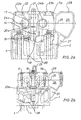
- the cylinder head 1 partially shown in Fig. 1 is a four-valve cylinder head for a four-cylinder autoignition Internal combustion engine.
- the cylinder head 1 is with cylinder head bolts 2 ( Figure 2) bolted to the crankcase of an internal combustion engine, wherein in Fig. 1, a cylinder 3 and a piston 4 indicated are.
- the cylinder head 1 is covered by a camshaft bearing frame 5a, with the camshaft bearing frame mounting screws. 6 is bolted to the cylinder head 1.
- a separate cover 7 is placed, which in turn is covered by a mounting space cover 8.
- a recess In the Camshaft bearing frame 5a is recessed per cylinder 9 a recess, extending through the cylinder head 1 into the piston 4 recessed combustion chamber continues.
- a Injection valve 10 is used, which with a fixing claw 11 with an injection valve mounting screw 12 on a support element 35 is attached.
- the injection valve 10 has a lateral Injector high-pressure line connection 13 and a leak oil line connection 36 on.
- the recess 9 is perpendicular in the median plane of the cylinder head 1 and the camshaft bearing frame 5a and exactly or possibly with a small lateral offset aligned in extension of the central axis of the associated cylinder.
- a Second recess 14 is arranged, which is inclined to the recess 9 also extends into the combustion chamber of the piston 4.
- a glow plug 15 is screwed, the over a cable connection 16 with the electrical system of the internal combustion engine is interconnected.
- the recess 9 and the second recess 14 go in the camshaft bearing frame 5a in a mounting space 17 via, which is over almost the entire length of the camshaft bearing frame (Fig. 4 and Fig. 5).
- a recess 18 embedded in the cylinder head from the side Disposal opening 19 goes to a Zylinderkopflteilsservicewand.
- the mouths of the disposal openings 19 of a row of cylinders can with each other via a side bus (and with a Collecting container).
- coolant spaces 20b In the cylinder head 1 are still usual coolant spaces 20b inserted, which flows through cooling water become.
- the cylinder head 1 has a cast along about the middle of the cylinder head 1 with lateral bypass the recesses 9 and the second recesses 14 extending Oil gallery 20a on, through the lubricating oil to the lubrication points and the Hydro tappets is performed.
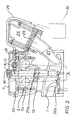
- FIG. 2a and 2b of Camshaft bearing frame 5b Essentially difference from FIG. 1 is shown in Figs. 2a and 2b of Camshaft bearing frame 5b with an integrated cover plate 21st fitted. Accordingly, in extension of the cylinder head bolts 2 and next to the camshaft bearing frame mounting bolts 6 openings 22 provided by the closure caps 23a, 23b are closable. Here are the caps 23a and 23b differently formable.
- the internal combustion engine has two overhead camshafts 24a, 24b, whose central axis through the parting plane 25 between the cylinder head 1 and the camshaft bearing frame 5b runs. Furthermore, in the right part of Fig. 2, the air intake line shown, which also from the parting plane 25 is divided into a lower and an upper part.
- the Air intake which may also be a charge air duct, is over Inlet channels 27 connected to the inlet valves of a cylinder. Furthermore, the through the parting plane 25 of the air intake 26 separate cover 28 integral with the camshaft bearing frame 5b formed. Incidentally, in Fig. 2a flats 40th shown on the camshafts 24a, 24b, each in the mounting position stand for the cylinder head bolts 2.
- the camshaft bearing frame 5a with a separate Cover 7 shown in this figure, in particular two different installation options of the injection line 29 shown are.
- the injection line 29 is in both variants the side injection valve high-pressure line connection 13 screwed and to the injection pump 30 acting as a high-pressure distributor injection pump is trained, led. Alternatively, the use a common rail system provided.
- the injection line 29 is guided through an opening 31 which extends through the camshaft bearing frame 5a and possibly the cylinder head 1 on a side wall of the cylinder head 1 extends.
- the injection line 29 outside the air intake 26th around to the injection pump 30 out.
- the mounting space cover 8 is designed as a plastic part and easy (as well as Figs. 4 and 5 can be seen) alsklippst.
- a camshaft bearing frame 5c is shown, which in turn has an integrated cover plate 21.
- the camshaft bearing frame fixing screws 6 are up to guided the cover plate 21 and sealed against this.
- the Injection line 29 is coaxial with the injection valve in this variant 10 tightened.
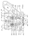
- Fig. 4 The cylinder head shown in Fig. 4 is so far completely assembled, so that it can be placed on a crankcase. additionally to the details already described to other figures, in Fig. 4 the fully assembled valve train with intake and exhaust valves, hydraulic tappets and camshafts shown. In each case concern the Components with the reference numerals having the index a, the Outlet side, while the components with the reference numerals, the Index b, which affect the inlet side.
- the intake and exhaust valves 34b, 34a have valve stems 41 which are in valve stem guides are guided. Sealed the valve stems 41 are opposite the valve stem guides through valve stem seals 45.
- valve stems 41 - actuated by the cam of Camshafts 24 - hydraulic tappet 46 the rest of the oil gallery 20a be supplied with pressure oil.
- Valve springs 47 hold the inputs and Outlet valves 34b, 34a in the unactuated state in their closed Position.
- the valve stems 41 are otherwise so to the block cylinder head longitudinal side walls 44a, 44b inclined to make an angle of about 10 °.
- Fig. 6 is a section through the cylinder head 1 is shown in the in particular, the course of the gas exchange channels is shown.
- the Outlet passages of a cylinder 3 are combined to form a trouser channel 48 and open into the cylinder head longitudinal side wall 44a.
- Opposite are the inlet channels 27 of the same cylinder. 3 as a swirl channel 42 and a tangential channel 43 is formed.
- the Swirl channel 42 and the tangential channel 43 have a common Mouth surface at an obtuse angle to the parting plane 25 is arranged (see, for example, Fig. 3).
- the tangential channel 43 of the cylinder 3 is guided so that it from a cylinder transverse side (meaning the side adjacent to the one to the right Cylinder is arranged) over the cylinder center of the cylinder 3 is guided to the second cylinder side.
- the associated Swirl duct 42 is behind a cylinder head screw whistle 49 ago the second cylinder side of the cylinder to the first cylinder side of the cylinder to the left.
- the rectangular openings 50a, 50b in the amount of cylinder head screw pipes along the cylinder head longitudinal side walls 44a, 44b are part of a Tragholm convincedes the crankcase and serve at the same time for oil removal from the cylinder head 1 into the crankcase or for transportation the blow-by gases from the crankcase into the cylinder head or camshaft frame.
- the cooling water passes through water drainage channels 55 in the cylinder head 1, flows through this and is on the opposite side by water descent channels 54 again led into the crankcase. Otherwise, the tangential channels 43 and the water descent channels 54 each have a free space 53r
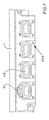
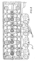
- Fig. 7 finally shows a view of the cylinder head longitudinal side wall 44a, ie the outlet side. Shown are the mouths of the individual Pantyhose 48, which is exactly symmetrical to the respective Cylinder center are arranged.
- the exhaust manifold is by means of four screws per cylinder attached to the cylinder head 1.
- Above the trouser channel 48 on the left side is a connecting flange 51 arranged on which a coolant return line can be connected is.
- This coolant return line leads through a Exhaust gas cooler, which is turned on in an exhaust gas recirculation line, has flowed through and for cooling the exhaust gas required coolant back to the cylinder head.
Description
- in den Nockenwellenlagerrahmen ist eine Kühlmittelsammelleitung eingelassen,
- in dem Nockenwellenlagerrahmen ist eine Schmieröleinfüllvorrichtung vorgesehen,
- die Ableitung der Blow-By-Gase vom Ölabscheider zur Verdichterseite des Abgasturboladers erfolgt über eine Querbohrung, die in den Nockenwellenlagerrahmen eingelassen ist,
- die Wasserführung vom Abgaskühler zum Zylinderkopf ist in den Nockenwellenlagerrahmen eingelassen,
- der Nockenwellenlagerrahmen übernimmt eine Tragfunktion für einen zu montierenden Ölabscheider und
- der Nockenwellenlagerrahmen hat angegossene Halterungen für zu verlegende Kraftstoffniederdruckleitungen und elektrische Kabel.
- Fig. 1:
- einen mittigen Längsschnitt durch Zylinderkopf und Nokkenwellenlagerrahmen mit separatem Deckel,
- Fig. 2a:
- einen Querschnitt durch Zylinderkopf und Nockenwellenlagerrahmen mit integrierter Deckelplatte,
- Fig. 2b:
- einen weiteren Querschnitt durch Zylinderkopf und Nokkenwellenlagerrahmen mit integrierter Deckelplatte,
- Fig. 3:
- einen Querschnitt durch einen Zylinderkopf und einen Nockenwellenlagerrahmen mit separatem Deckel und alternativen Leitungsführungen für die Einspritzleitungen,
- Fig. 4:
- einen Querschnitt durch den Zylinderkopf mit eingesetztem Ventilen Hydrostößeln und Nockenwellen,
- Fig. 5:
- einen Querschnitt durch den Zylinderkopf und den Nokkenwellenlagerrahmen mit integrierter Deckelplatte und separater Abdeckung der Luftansaugleitung,
- Fig. 6:
- einen Schnitt durch den Zylinderkopf,
- Fig. 7:
- eine Ansicht einer Zylinderkopflängsseitenwand und
- Fig. 8:
- eine Ansicht einer Zylinderkopf-Anschraub-Dichtfläche zum Nockenwellenlagerrahmen.
Claims (7)
- Selbstzündende Brennkraftmaschine mit einem Zylinderkopf, die weiterhin ein Kurbelgehäuse und eine darin drehbar gelagerte Kurbelwelle aufweist, an der jeweils mit einem Kolben verbundene Pleuel angelenkt sind, wobei der Kolben (4) in einem von dem Zylinderkopf (1) abgedeckten Zylinder (3) unter Bildung eines Brennraums bewegbar ist, wobei im Bereich des Zylinderkopfs (1) zwei Nockenwellen (24a, 24b) angeordnet sind, die je Zylinder (3) Gaswechselventile, insbesondere zwei Einlassventile (34b) und zwei Auslassventile (34a) steuern, wobei die Einlassventile (34b) und die Auslassventile (34a) mit den Ventilschäften (41a, 41b) zu den Zylinderkopflängsseitenwänden (44a, 44b) nach außen geneigt angeordnet sind, weiterhin ein Einspritzventil (10) in eine zentrale Ausnehmung (9) einsetzbar ist, die als von schmierölführenden und/oder kühlmittelführenden Räumen (20a, 20b, 20c) getrennter Bereich ausgebildet ist, und sich die Ausnehmung (9) vom Brennraum zumindest bis in Höhe der Nockenwellenachsen erstreckt,
dadurch gekennzeichnet, dass der Zylinderkopf (1) eine durch die Nockenwellen-Achsen verlaufende Trennebene (25) aufweist, an die sich ein Nockenwellenlagerrahmen (5a, 5b, 5c) anschließt, wobei die Nockenwellen (24a, 24b) zwischen Zylinderkopf (1) und Nockenwellenlagerrahmen (5a, 5b, 5c) gelagert sind, dass die Ausnehmung (9) sich als getrennter Bereich durch den Nockenwellenlagerrahmen (5a, 5b, 5c) hindurch erstreckt und in einen Montageraum (17) im oberen Nockenwellenlagerrahmen (5a, 5b, 5c) mündet, dass ein Glühstift (15) in eine Zweitausnehmung (14) einsetzbar ist, die als von schmierölführenden und/oder kühlmittelführenden Räumen (20) getrennter Bereich ausgebildet ist, und dass die Zweitausnehmung (14) sich vom Brennraum zumindest bis in Höhe der Nockenwellenachsen erstreckt - Zylinderkopf nach Anspruch 1,
dadurch gekennzeichnet, dass die Nockenwellen (24a, 24b) so zu den Zylinderkopfschrauben (2) angeordnet sind, dass bei eingelegten Nockenwellen (24a, 24b) und aufgeschraubten Nockenwellenlagerrahmen (5a, 5b, 5c) die Zylinderkopfschraubenköpfe in der Form zugänglich sind, dass die Nockenwellenschäfte im Bereich der Zylinderkopfschrauben (2) Abflachungen (40) aufweisen - Zylinderkopf nach einem der Ansprüche 1 oder 2,
dadurch gekennzeichnet, dass der Nockenwellenlagerrahmen (5a, 5b, 5c) zylinderkopfseitig Dichtnutbereiche (52) aufweist, in die Gummiformdichtungen und/oder Runddichtringe einsetzbar sind. - Zylinderkopf nach einem der vorherigen Ansprüche,
dadurch gekennzeichnet, dass die Einlaßkanäle (27) eine zur Trennebene (25) im stumpfen Winkel ausgebildete gemeinsame Mündungsfläche aufweisen, an die eine Luftansaugleitung (26) anschließbar ist. - Zylinderkopf nach einem der vorherigen Ansprüche,
dadurch gekennzeichnet, dass die Einlasskanäle (27) eines Zylinders (3) als ein Drallkanal (42) und ein Tangentialkanal (43) ausgebildet sind, und dass die beiden Auslasskanäle eines Zylinders (3) zu einem Hosenkanal zusammengefasst sind und im rechten Winkel zur Trennebene (25) in einer Zylinderkopflängsseitenwand (44a) münden. - Zylinderkopf nach Anspruch 1,
dadurch gekennzeichnet, dass die Zweitausnehmung (14) sich durch den Zylinderkopf (1) hindurch erstreckt und in den Montageraum (17) im oberen Nockenwellenlagerrahmen (5a, 5b, 5c) mündet. - Zylinderkopf nach Anspruch 5,
dadurch gekennzeichnet, dass zwischen dem Tangentialkanal (43) und einem Wasserabstiegskanal (54) ein Freiraum (53) angeordnet ist.
Applications Claiming Priority (2)
| Application Number | Priority Date | Filing Date | Title |
|---|---|---|---|
| DE19729947A DE19729947A1 (de) | 1997-07-12 | 1997-07-12 | Vierventil-Blockzylinderkopf mit schräg angeordneten Gaswechselventilen |
| DE19729947 | 1997-07-12 |
Publications (3)
| Publication Number | Publication Date |
|---|---|
| EP0890726A2 EP0890726A2 (de) | 1999-01-13 |
| EP0890726A3 EP0890726A3 (de) | 1999-08-25 |
| EP0890726B1 true EP0890726B1 (de) | 2005-02-23 |
Family
ID=7835528
Family Applications (1)
| Application Number | Title | Priority Date | Filing Date |
|---|---|---|---|
| EP98110044A Expired - Lifetime EP0890726B1 (de) | 1997-07-12 | 1998-05-29 | Vierventil-Blockzylinderkopf mit schräg angeordneten Gaswechselventilen |
Country Status (3)
| Country | Link |
|---|---|
| EP (1) | EP0890726B1 (de) |
| AT (1) | ATE289655T1 (de) |
| DE (2) | DE19729947A1 (de) |
Families Citing this family (2)
| Publication number | Priority date | Publication date | Assignee | Title |
|---|---|---|---|---|
| DE10138698B4 (de) * | 2000-08-11 | 2008-02-07 | Honda Giken Kogyo K.K. | Motor in DOHC-Bauart |
| DE102008058473A1 (de) * | 2008-11-21 | 2010-06-10 | Mtu Friedrichshafen Gmbh | Brennkraftmaschine mit einem Zylinderkopf, einer Zylinderkopfhaube und einer Abschlusshaube |
Family Cites Families (10)
| Publication number | Priority date | Publication date | Assignee | Title |
|---|---|---|---|---|
| DE7203995U (de) * | 1972-04-27 | Automobiles M Berliet | Zylinderkopf für eine Brennkraftmaschine, insbesondere für einen Dieselmotor | |
| DE902200C (de) * | 1950-05-15 | 1954-01-21 | Semt | Zentrales Brennstoffventil fuer Brennkraftmaschinen |
| JPS6176712A (ja) * | 1984-09-21 | 1986-04-19 | Nissan Motor Co Ltd | 内燃機関の動弁装置 |
| AT404864B (de) * | 1989-10-25 | 1999-03-25 | Avl Verbrennungskraft Messtech | Brennkraftmaschine mit mehr als zwei ventilen je zylinder |
| DE4117162A1 (de) | 1991-05-25 | 1992-11-26 | Kloeckner Humboldt Deutz Ag | Zylinderkopf fuer eine brennkraftmaschine |
| SE506129C2 (sv) * | 1992-12-23 | 1997-11-10 | Scania Cv Ab | Cylinderhuvud för förbränningsmotor |
| DE4315233A1 (de) * | 1993-05-07 | 1994-07-28 | Daimler Benz Ag | Direkteinspritzende Brennkraftmaschine mit einem im Zylinderkopf zwischen Gaswechselventilen angeordneten Kraftstoffeinspritzventil |
| DE4323073A1 (de) * | 1993-07-10 | 1995-01-12 | Audi Ag | Hubkolben-Brennkraftmaschine |
| DE19534904B4 (de) * | 1994-09-29 | 2008-07-17 | Volkswagen Ag | Zylinderkopf einer Brennkraftmaschine |
| DE19548088C1 (de) * | 1995-12-21 | 1997-07-17 | Daimler Benz Ag | Zylinderkopf für eine Brennkraftmaschine |
-
1997
- 1997-07-12 DE DE19729947A patent/DE19729947A1/de not_active Ceased
-
1998
- 1998-05-29 EP EP98110044A patent/EP0890726B1/de not_active Expired - Lifetime
- 1998-05-29 DE DE59812589T patent/DE59812589D1/de not_active Expired - Fee Related
- 1998-05-29 AT AT98110044T patent/ATE289655T1/de not_active IP Right Cessation
Also Published As
| Publication number | Publication date |
|---|---|
| DE19729947A1 (de) | 1999-01-14 |
| EP0890726A3 (de) | 1999-08-25 |
| DE59812589D1 (de) | 2005-03-31 |
| ATE289655T1 (de) | 2005-03-15 |
| EP0890726A2 (de) | 1999-01-13 |
Similar Documents
| Publication | Publication Date | Title |
|---|---|---|
| DE102011088141B4 (de) | Zylinderblockanordnung | |
| DE102010007234B4 (de) | Verbrennungsmotor mit einem auf dem Zylinderkopfdeckel angeordneten Membranventil | |
| DE60303039T2 (de) | Brennkraftmaschine | |
| EP0883740B1 (de) | Brennkraftmaschine und verfahren zu deren herstellung | |
| EP0688946B1 (de) | Zylinderkopfanordnung einer Brennkraftmaschine | |
| EP1674711B1 (de) | Aufgeladene Dieselbrennkraftmaschine mit einer Common-Rail-Einspritzanlage | |
| DE102018116664A1 (de) | Zylinderkopfdeckelstruktur für einen motor | |
| DE19818700A1 (de) | Brennkraftmaschine mit einem integrierten Front-End | |
| DE10359221B4 (de) | 4-Takt-Motor für ein Motorrad | |
| EP0890726B1 (de) | Vierventil-Blockzylinderkopf mit schräg angeordneten Gaswechselventilen | |
| EP2627884B1 (de) | Brennkraftmaschine sowie verfahren zum herstellen einer solchen brennkraftmaschine | |
| EP0782665A1 (de) | Zylinderkopf | |
| EP0890713B1 (de) | Brennkraftmaschine mit Nockenwellenlagerrahmen | |
| DE19548329A1 (de) | Otto-Verbrennungsmotor mit Kraftstoffeinspritzventil | |
| EP1146219A1 (de) | Verbrennungsmotor mit Zylindern in enger V-Anordnung | |
| DE19849912A1 (de) | Flüssigkeitsgekühlte Brennkraftmaschine | |
| DE4426557A1 (de) | Diagonal angeordnete Ventile | |
| EP1101028B1 (de) | Zylinderkopf für eine hubkolben-brennkraftmaschine | |
| DE19959989A1 (de) | Lagerung zumindest einer Nockenwelle | |
| EP0782666B1 (de) | Kombinationsgehäuse | |
| WO2010043242A1 (de) | Zylinderkopf mit nockenwellenanordnung | |
| DE202015106691U1 (de) | Nockenträger aus Verbundmaterial | |
| EP1795731B1 (de) | Abgasrückführung bei einer Brennkraftmaschine | |
| EP0782668B1 (de) | Zwischengehäuse für eine brennkraftmaschine | |
| DE4338186A1 (de) | Hubkolbenbrennkraftmaschine |
Legal Events
| Date | Code | Title | Description |
|---|---|---|---|
| PUAI | Public reference made under article 153(3) epc to a published international application that has entered the european phase |
Free format text: ORIGINAL CODE: 0009012 |
|
| AK | Designated contracting states |
Kind code of ref document: A2 Designated state(s): AT DE ES FR GB SE |
|
| AX | Request for extension of the european patent |
Free format text: AL;LT;LV;MK;RO;SI |
|
| PUAL | Search report despatched |
Free format text: ORIGINAL CODE: 0009013 |
|
| AK | Designated contracting states |
Kind code of ref document: A3 Designated state(s): AT BE CH CY DE DK ES FI FR GB GR IE IT LI LU MC NL PT SE |
|
| AX | Request for extension of the european patent |
Free format text: AL;LT;LV;MK;RO;SI |
|
| 17P | Request for examination filed |
Effective date: 20000205 |
|
| AKX | Designation fees paid |
Free format text: AT DE ES FR GB SE |
|
| 17Q | First examination report despatched |
Effective date: 20020613 |
|
| GRAP | Despatch of communication of intention to grant a patent |
Free format text: ORIGINAL CODE: EPIDOSNIGR1 |
|
| GRAS | Grant fee paid |
Free format text: ORIGINAL CODE: EPIDOSNIGR3 |
|
| GRAA | (expected) grant |
Free format text: ORIGINAL CODE: 0009210 |
|
| AK | Designated contracting states |
Kind code of ref document: B1 Designated state(s): AT DE ES FR GB SE |
|
| REG | Reference to a national code |
Ref country code: GB Ref legal event code: FG4D Free format text: NOT ENGLISH |
|
| REF | Corresponds to: |
Ref document number: 59812589 Country of ref document: DE Date of ref document: 20050331 Kind code of ref document: P |
|
| PG25 | Lapsed in a contracting state [announced via postgrant information from national office to epo] |
Ref country code: SE Free format text: LAPSE BECAUSE OF FAILURE TO SUBMIT A TRANSLATION OF THE DESCRIPTION OR TO PAY THE FEE WITHIN THE PRESCRIBED TIME-LIMIT Effective date: 20050523 |
|
| PG25 | Lapsed in a contracting state [announced via postgrant information from national office to epo] |
Ref country code: ES Free format text: LAPSE BECAUSE OF FAILURE TO SUBMIT A TRANSLATION OF THE DESCRIPTION OR TO PAY THE FEE WITHIN THE PRESCRIBED TIME-LIMIT Effective date: 20050603 |
|
| GBT | Gb: translation of ep patent filed (gb section 77(6)(a)/1977) |
Effective date: 20050518 |
|
| ET | Fr: translation filed | ||
| PLBE | No opposition filed within time limit |
Free format text: ORIGINAL CODE: 0009261 |
|
| STAA | Information on the status of an ep patent application or granted ep patent |
Free format text: STATUS: NO OPPOSITION FILED WITHIN TIME LIMIT |
|
| 26N | No opposition filed |
Effective date: 20051124 |
|
| PGFP | Annual fee paid to national office [announced via postgrant information from national office to epo] |
Ref country code: AT Payment date: 20060406 Year of fee payment: 9 |
|
| PGFP | Annual fee paid to national office [announced via postgrant information from national office to epo] |
Ref country code: FR Payment date: 20060411 Year of fee payment: 9 |
|
| PGFP | Annual fee paid to national office [announced via postgrant information from national office to epo] |
Ref country code: GB Payment date: 20060412 Year of fee payment: 9 |
|
| PGFP | Annual fee paid to national office [announced via postgrant information from national office to epo] |
Ref country code: DE Payment date: 20060526 Year of fee payment: 9 |
|
| GBPC | Gb: european patent ceased through non-payment of renewal fee |
Effective date: 20070529 |
|
| PG25 | Lapsed in a contracting state [announced via postgrant information from national office to epo] |
Ref country code: AT Free format text: LAPSE BECAUSE OF NON-PAYMENT OF DUE FEES Effective date: 20070529 |
|
| REG | Reference to a national code |
Ref country code: FR Ref legal event code: ST Effective date: 20080131 |
|
| PG25 | Lapsed in a contracting state [announced via postgrant information from national office to epo] |
Ref country code: DE Free format text: LAPSE BECAUSE OF NON-PAYMENT OF DUE FEES Effective date: 20071201 |
|
| PG25 | Lapsed in a contracting state [announced via postgrant information from national office to epo] |
Ref country code: GB Free format text: LAPSE BECAUSE OF NON-PAYMENT OF DUE FEES Effective date: 20070529 |
|
| PG25 | Lapsed in a contracting state [announced via postgrant information from national office to epo] |
Ref country code: FR Free format text: LAPSE BECAUSE OF NON-PAYMENT OF DUE FEES Effective date: 20070531 |