EP0887162A2 - Butée pour un capot protecteur d'une scie circulaire - Google Patents
Butée pour un capot protecteur d'une scie circulaire Download PDFInfo
- Publication number
- EP0887162A2 EP0887162A2 EP98304530A EP98304530A EP0887162A2 EP 0887162 A2 EP0887162 A2 EP 0887162A2 EP 98304530 A EP98304530 A EP 98304530A EP 98304530 A EP98304530 A EP 98304530A EP 0887162 A2 EP0887162 A2 EP 0887162A2
- Authority
- EP
- European Patent Office
- Prior art keywords
- blade guard
- blade
- saw
- spring
- spring member
- Prior art date
- Legal status (The legal status is an assumption and is not a legal conclusion. Google has not performed a legal analysis and makes no representation as to the accuracy of the status listed.)
- Withdrawn
Links
Images
Classifications
-
- B—PERFORMING OPERATIONS; TRANSPORTING
- B27—WORKING OR PRESERVING WOOD OR SIMILAR MATERIAL; NAILING OR STAPLING MACHINES IN GENERAL
- B27G—ACCESSORY MACHINES OR APPARATUS FOR WORKING WOOD OR SIMILAR MATERIALS; TOOLS FOR WORKING WOOD OR SIMILAR MATERIALS; SAFETY DEVICES FOR WOOD WORKING MACHINES OR TOOLS
- B27G19/00—Safety guards or devices specially adapted for wood saws; Auxiliary devices facilitating proper operation of wood saws
- B27G19/02—Safety guards or devices specially adapted for wood saws; Auxiliary devices facilitating proper operation of wood saws for circular saws
- B27G19/04—Safety guards or devices specially adapted for wood saws; Auxiliary devices facilitating proper operation of wood saws for circular saws for manually-operated power-driven circular saws
Definitions
- This invention relates to circular saws and, more particularly, to an improved blade guard stop for a circular saw.
- a typical circular saw includes a housing having an operator's handle, an electric motor supported by the housing, a rotating saw blade driven by the motor, and a shoe plate supporting the circular saw against a workpiece.
- the housing forms a fixed blade guard covering the upper portion of the saw blade.
- the circular saw also includes a rotatable lower blade guard.
- the lower blade guard is rotatable about the saw blade axis, so that, during cutting operations, the lower blade guard is rotated to an uncovered or "non-surround" position via engagement with the workpiece.
- the lower blade guard is biased back to the covered or “surround” position by a coil spring and rotates until engaging a blade guard stop mounted on the housing.
- the blade guard stop includes a plastic or rubber grommet, washer or spacer supported by a suitable fastener mounted on the housing.
- the typical blade guard stop is subjected to repeated impacts by the rotating lower blade guard.
- the fastener In order to withstand these repeated impacts, the fastener must usually be specially manufactured.
- the shoe plate is vertically and/or pivotally movable relative to the axis of the saw blade to adjust the depth of cut and the bevel angle of the circular saw.
- the blade guard moves along the surface of the blade guard stop. Friction is created between the metallic blade guard and the plastic or rubber member of the blade guard stop. Additionally, when the circular saw is adjusted to a different depth of cut or bevel angle, the lower blade guard will impact the blade guard stop from a different direction.
- the present invention provides an improved blade guard stop for a circular saw.
- the improved blade guard stop overcomes the problems of prior art blade guard stops.
- the invention provides an elongated flexible, impact absorbing blade guard stop member.
- the blade guard stop member is a spring member and, specifically, is a leaf spring.
- the blade guard stop member is formed of a low friction material, thus reducing the friction between the blade guard and the blade guard stop during adjustment of the circular saw.
- the spring member absorbs the impact of the lower blade guard from several different directions, as is necessary in a drop shoe and/or pivot shoe circular saw.
- An advantage of the blade guard stop of the present invention is that the blade guard stop is better able to withstand the repeated impacts by the lower blade guard over the life of the circular saw. This greatly increases the life of the blade guard stop and the life of the circular saw.
- Another advantage of the blade guard stop is that it is inexpensive to manufacture.
- Yet another advantage of the blade guard stop is that the reduced friction between the blade guard and the blade guard stop makes adjustment of the circular saw shoe easier.
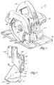
- Fig. 1 is a perspective view of a circular saw embodying the invention.
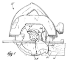
- Fig. 2 is a side elevational view of the circular saw shown in Fig. 1 with portions cut-away.
- Fig. 3 is an enlarged, partial perspective view of the circular saw shown in Fig. 1 with portions cut-away to more clearly illustrate the blade guard stop.
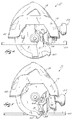
- Fig. 4 is a side elevational view of the circular saw and the blade guard stop, showing the shoe adjusted for a maximum depth of cut.
- Fig. 5 is a side elevational view of the circular saw and the blade guard stop, showing the shoe adjusted to a minimum depth of cut.
- a circular saw 10 embodying the invention is illustrated in Fig. 1.
- the circular saw 10 includes a housing 14 having an operator's handle 18.
- An electric motor (not shown) is supported by the housing 14.
- the motor is selectively connected to a power source (not shown) by a switch (not shown).
- the motor drives a shaft 30 having a rotational axis 34.
- the circular saw 10 also includes a saw blade 38 supported on the drive shaft 30 and driven by the motor for rotation about the axis 34.
- a portion of the housing 14 serves as a fixed blade guard 42 covering the upper portion of the saw blade 38.
- the housing 14 also includes a shoe plate 46 supported by the housing 14.
- the shoe plate 46 includes an opening 50 through which a portion of the saw blade 38 extends.
- the shoe plate 46 is adjustable relative to the housing 14 and relative to the axis 34 to vary the depth of cut (see Figs. 4 and 5) and bevel angle of the saw blade 38.
- An adjustment mechanism 54 is operable to adjust the shoe plate 46, as described more fully below.
- the circular saw 10 also includes (see Fig. 2) a rotatable lower blade guard 58.
- the blade guard 58 is supported by the housing 14 for rotation about the axis 34 and generally in a plane defined by the blade guard 58.
- the blade guard 58 is rotatable between a first or uncovered position (shown in phantom in Fig. 2), in which the lower portion of the saw blade 38 is exposed to cut a workpiece W, and a second or covered position (shown in solid lines in Fig. 2), in which the lower portion of the saw blade 38 is covered.
- the blade guard 58 includes (see Fig. 3) a planar portion 59 that is substantially parallel to the saw blade 38 and that defines the plane in which the blade guard 58 rotates.
- the blade guard 58 also includes an annular L-shaped portion 60 extending from the planar portion 59 and covering a portion of the teeth of the saw blade 38.
- a workpiece engaging portion 61 extends from the L-shaped portion 60 and is engageable with the workpiece W.
- the blade guard 58 is constructed of a low friction material such as aluminum.
- the circular saw 10 also includes (see Fig. 2) a biasing member 62 connected to the blade guard 58.
- the biasing member 62 applies a biasing force to rotate the blade guard 58 toward the covered position.
- the biasing member 62 is a spring connected between the housing 14 and the blade guard 58.
- the circular saw 10 also includes (see Fig. 3) an elongated, flexible, impact absorbing spring member 66 supported by the housing 14.
- the spring member 66 absorbs the rotational force of the blade guard 58 as the blade guard 58 moves from the uncovered position (shown in phantom in Fig. 2) to the covered position (shown in solid lines in Fig. 2).
- the spring member 66 stops the blade guard 58 in the covered position and thereby prevents rotation of the blade guard 58 beyond the covered position.
- the spring member 66 counteracts the biasing force of the biasing member 62.
- the spring member 66 is (see Fig. 3) an integrally formed one-piece member and includes a body portion 70.
- the body portion 70 is elongated and flexible and includes upper and lower end portions 71 and 72.
- a flexible stop portion 74 extends from end portion 72.
- the stop portion 74 is generally rounded or circular and includes a smooth, arcuate engaging surface 75. Both the body portion 70 and the stop portion 74 flex to absorb the rotational force of the blade guard 58 and the biasing force of the biasing member 62.
- the spring member 66 also includes a mounting portion 78 connected to the end portion 71.
- the mounting portion 78 is connected to the housing 14 in a suitable manner, such as by riveting, welding, or the use of screws, so that the spring member 66 is supported by the housing 14.
- the mounting portion 78 is connected by rivets or fasteners 82 to the adjustment mechanism 54 of the shoe plate 46 so that the spring member 66 is movable with the shoe plate 46 when the shoe plate 46 is adjusted.
- the spring member 66 is a leaf spring and is constructed of a low friction material such as steel. Also, the spring member 66 is oriented so that the body portion 70 and the stop portion are substantially in the rotational plane of the blade guard 58.
- the circular saw 10 is placed against the surface of the workpiece W.
- the operator engages the motor to drive the saw blade 38.
- the workpiece engaging portion 61 of the blade guard 58 engages an edge of the workpiece W, causing the blade guard 58 to rotate from the covered position to the uncovered position.
- the saw blade 38 is thus exposed as it cuts through the workpiece W.
- the force of the workpiece W on the blade guard 58 overcomes the biasing force of the biasing member 62 and causes the blade guard 58 to move to the uncovered position.
- the biasing force of the biasing member 62 causes the blade guard 58 to rotate from the uncovered position to the covered position.
- the engaging surface of the blade guard 58 impacts the engaging surface 75 of the spring member 66 causing the stop portion 74 and the body portion 70 to flex and absorb the impact of the blade guard 58 and to absorb the biasing force of the biasing member 62.
- the body portion 70 and the stop portion 74 continue to apply a constant biasing force to the blade guard 58 to counteract the biasing force of the biasing member 62.
- the illustrated circular saw 10 is a drop shoe and pivot shoe circular saw.
- the shoe plate 46 is adjustable relative to the housing 14 and relative to the saw blade 38 to adjust the cutting depth of the saw blade 38 and the bevel angle of the saw blade 38. Normally, the shoe plate 46 is adjusted when the blade guard 58 is in the covered position contacting the spring member 66. As the shoe plate 46 is adjusted, the blade guard 58 moves against the surface of the stop portion 74. Because the blade guard 58 and the spring member 66 are constructed of a low friction material, friction between the blade guard 58 and the spring member 66 is greatly reduced.
- the shoe plate 46 is adjustable to change the depth of cut of the saw blade 38.
- a first depth position in this case a maximum depth of cut for the saw blade 38
- the blade guard 58 engages a first portion of the spring member 66 in a first direction having a generally upward or vertical vector component, illustrated by arrow "A”.
- the blade guard 58 engages a second portion of the spring member 66 in a second direction having a generally horizontal vector component, illustrated by arrow "B".
- the blade guard 58 With the blade guard 58 in any intermediate position between the maximum depth of cut position (shown in Fig. 4) or the minimum depth of cut position (shown in Fig. 5), the blade guard 58 engages another portion of the spring member 66 in a direction having a vector component that is between horizontal and vertical. This vector component depends on the position of the shoe plate 46 and the curvature of the engaging surface of the blade guard 58. Regardless of the position, the spring member 66 absorbs the rotational force of the blade guard 58 and the biasing force of the biasing member 62 from both the first direction and the second direction.
- the prior art blade guard stop member assembly failed after approximately 84,600 cycles or impacts by a rotatable lower blade guard. Because the prior art blade guard stop experiences two failures (the rubber bumper and the fastener each fail), the mean time between failure of a component of the prior art blade guard stop member is approximately 42,300 cycles.
Applications Claiming Priority (2)
| Application Number | Priority Date | Filing Date | Title |
|---|---|---|---|
| US08/882,552 US5873169A (en) | 1997-06-25 | 1997-06-25 | Blade guard stop for a circular saw |
| US882552 | 2001-06-15 |
Publications (2)
| Publication Number | Publication Date |
|---|---|
| EP0887162A2 true EP0887162A2 (fr) | 1998-12-30 |
| EP0887162A3 EP0887162A3 (fr) | 2000-02-23 |
Family
ID=25380830
Family Applications (1)
| Application Number | Title | Priority Date | Filing Date |
|---|---|---|---|
| EP98304530A Withdrawn EP0887162A3 (fr) | 1997-06-25 | 1998-06-09 | Butée pour un capot protecteur d'une scie circulaire |
Country Status (2)
| Country | Link |
|---|---|
| US (1) | US5873169A (fr) |
| EP (1) | EP0887162A3 (fr) |
Cited By (1)
| Publication number | Priority date | Publication date | Assignee | Title |
|---|---|---|---|---|
| DE112008003976B4 (de) | 2008-09-05 | 2023-06-29 | Bosch Power Tools (China) Co., Ltd. | Schutzvorrichtung |
Families Citing this family (12)
| Publication number | Priority date | Publication date | Assignee | Title |
|---|---|---|---|---|
| DE19938524A1 (de) * | 1998-08-14 | 2000-02-17 | Milwaukee Electric Tool Corp | Verbesserte Kreissäge |
| JP3710683B2 (ja) * | 1999-12-16 | 2005-10-26 | 株式会社マキタ | 携帯マルノコ |
| US6536120B1 (en) * | 2000-10-27 | 2003-03-25 | Steven J. Langis | Powered circular saw for left or right handed operation |
| JP3983997B2 (ja) * | 2001-04-26 | 2007-09-26 | 株式会社マキタ | マルノコ |
| US6484405B1 (en) * | 2001-10-01 | 2002-11-26 | John D. Martelli | Rotary wheel cutting apparatus with a spring-biased blade cover |
| CA2422984A1 (fr) * | 2003-03-20 | 2004-09-20 | Claude Auger | Methode et appareil permettant de diminuer l'endommagement de la lame de scie circulaire d'une ebrancheuse |
| US7980163B2 (en) * | 2008-05-20 | 2011-07-19 | Black & Decker Inc. | Air deflector assemblies for miter saws |
| US20110252653A1 (en) * | 2010-04-19 | 2011-10-20 | Jason Twedell | Adjustable handle for hand held circular saw |
| WO2014127037A2 (fr) * | 2013-02-12 | 2014-08-21 | JPL Global, LLC | Pare-poussière pour scies circulaires |
| US10875109B1 (en) | 2018-04-30 | 2020-12-29 | Kreg Enterprises, Inc. | Adaptive cutting system |
| JP7299111B2 (ja) * | 2019-09-03 | 2023-06-27 | 株式会社マキタ | 携帯用切断機 |
| USD951051S1 (en) * | 2020-01-02 | 2022-05-10 | Techtronic Cordless Gp | Circular saw |
Citations (2)
| Publication number | Priority date | Publication date | Assignee | Title |
|---|---|---|---|---|
| US2072750A (en) * | 1934-07-26 | 1937-03-02 | George E Hampton | Portable electric saw |
| US3733701A (en) * | 1972-01-26 | 1973-05-22 | Singer Co | Lower guard for circular saws |
Family Cites Families (11)
| Publication number | Priority date | Publication date | Assignee | Title |
|---|---|---|---|---|
| US950994A (en) * | 1909-03-06 | 1910-03-01 | Charles H Burbank | Saw-guard. |
| US1738896A (en) * | 1929-07-13 | 1929-12-10 | Swift & Co | Meat-saw guard |
| US1813231A (en) * | 1930-03-24 | 1931-07-07 | Stanley Works | Motor driven hand tool |
| US1830580A (en) * | 1930-08-16 | 1931-11-03 | Wappat Inc | Electric handsaw |
| US1811577A (en) * | 1930-08-21 | 1931-06-23 | Stanley Works | Hand tool |
| US1900553A (en) * | 1931-02-04 | 1933-03-07 | Syntron Co | Portable motor driven saw |
| US2061707A (en) * | 1936-04-02 | 1936-11-24 | Kleiman Morris | Pinker guard and fabric guide |
| US2828784A (en) * | 1956-10-17 | 1958-04-01 | Stanley Works | Saw blade guard for power driven portable circular saw with tiltable table |
| US2963056A (en) * | 1958-06-05 | 1960-12-06 | Vernon W Rickford | Electric saw safety guard retractor |
| JPS5078998A (fr) * | 1973-11-15 | 1975-06-27 | ||
| US4693008A (en) * | 1985-05-07 | 1987-09-15 | Mallard Products, Incorporated | Releasable separate member latching device for a portable hand tool |
-
1997
- 1997-06-25 US US08/882,552 patent/US5873169A/en not_active Expired - Fee Related
-
1998
- 1998-06-09 EP EP98304530A patent/EP0887162A3/fr not_active Withdrawn
Patent Citations (2)
| Publication number | Priority date | Publication date | Assignee | Title |
|---|---|---|---|---|
| US2072750A (en) * | 1934-07-26 | 1937-03-02 | George E Hampton | Portable electric saw |
| US3733701A (en) * | 1972-01-26 | 1973-05-22 | Singer Co | Lower guard for circular saws |
Cited By (1)
| Publication number | Priority date | Publication date | Assignee | Title |
|---|---|---|---|---|
| DE112008003976B4 (de) | 2008-09-05 | 2023-06-29 | Bosch Power Tools (China) Co., Ltd. | Schutzvorrichtung |
Also Published As
| Publication number | Publication date |
|---|---|
| EP0887162A3 (fr) | 2000-02-23 |
| US5873169A (en) | 1999-02-23 |
Similar Documents
| Publication | Publication Date | Title |
|---|---|---|
| US5873169A (en) | Blade guard stop for a circular saw | |
| JP2717534B2 (ja) | 丸鋸盤における安全カバー装置 | |
| EP1577065B1 (fr) | Support pour lame de coupe et moteur à mécanisme de réglage d'hauteur et d'angle | |
| JP2903347B2 (ja) | 携帯用丸鋸 | |
| CA1121696A (fr) | Outl electromecanique, et modes de fonctionnement | |
| US4245533A (en) | Motorized circular miter chop saw | |
| US3701369A (en) | Circular saw | |
| EP0541051B1 (fr) | Tronçonneuse | |
| US6681493B2 (en) | Circular saws having bevel angle setting mechanism | |
| US7874075B2 (en) | Portable cutting machine | |
| US6971297B1 (en) | Guard and control apparatuses for sliding compound miter saw | |
| GB2441031A (en) | A hand-held circular saw with angularly adjustable guide plate | |
| US7556401B2 (en) | Adjustable laser module | |
| JP2006306103A (ja) | マイタ鋸用斜角ロックアセンブリ | |
| CA2150066A1 (fr) | Support reglable pour piece a usiner de scie a onglet combinee | |
| US5271155A (en) | Hand circular saw | |
| US4265154A (en) | Motorized miter saw fence mounting | |
| US5140754A (en) | Power tool protective hood positioning system and method of manufacturing the same | |
| US3658102A (en) | Portable band saw | |
| US5901450A (en) | Rip guide for a circular saw | |
| JP2011245564A (ja) | 切断工具における可動カバーの位置調整機構 | |
| US5947173A (en) | Cutting apparatus for wood or the like | |
| EP0875324B1 (fr) | Scie à table | |
| US4084645A (en) | Apparatus for securing T-edging and similar edging bands | |
| JPS6234725Y2 (fr) |
Legal Events
| Date | Code | Title | Description |
|---|---|---|---|
| PUAI | Public reference made under article 153(3) epc to a published international application that has entered the european phase |
Free format text: ORIGINAL CODE: 0009012 |
|
| AK | Designated contracting states |
Kind code of ref document: A2 Designated state(s): AT BE CH CY DE DK ES FI FR GB GR IE IT LI LU MC NL PT SE |
|
| AX | Request for extension of the european patent |
Free format text: AL;LT;LV;MK;RO;SI |
|
| PUAL | Search report despatched |
Free format text: ORIGINAL CODE: 0009013 |
|
| AK | Designated contracting states |
Kind code of ref document: A3 Designated state(s): AT BE CH CY DE DK ES FI FR GB GR IE IT LI LU MC NL PT SE |
|
| AX | Request for extension of the european patent |
Free format text: AL;LT;LV;MK;RO;SI |
|
| AKX | Designation fees paid | ||
| STAA | Information on the status of an ep patent application or granted ep patent |
Free format text: STATUS: THE APPLICATION IS DEEMED TO BE WITHDRAWN |
|
| 18D | Application deemed to be withdrawn |
Effective date: 20000824 |
|
| REG | Reference to a national code |
Ref country code: DE Ref legal event code: 8566 |