BACKGROUND OF THE INVENTION
This invention relates to circular saws and, more
particularly, to an improved blade guard stop for a
circular saw.
A typical circular saw includes a housing having
an operator's handle, an electric motor supported by
the housing, a rotating saw blade driven by the motor,
and a shoe plate supporting the circular saw against a
workpiece. The housing forms a fixed blade guard
covering the upper portion of the saw blade. The
circular saw also includes a rotatable lower blade
guard. The lower blade guard is rotatable about the
saw blade axis, so that, during cutting operations, the
lower blade guard is rotated to an uncovered or "non-surround"
position via engagement with the workpiece.
The lower blade guard is biased back to the covered or
"surround" position by a coil spring and rotates until
engaging a blade guard stop mounted on the housing.
Typically, the blade guard stop includes a plastic or
rubber grommet, washer or spacer supported by a
suitable fastener mounted on the housing.
During the life of the circular saw, the typical
blade guard stop is subjected to repeated impacts by
the rotating lower blade guard. In order to withstand
these repeated impacts, the fastener must usually be
specially manufactured.
With a drop shoe or pivot shoe type of circular
saw, the shoe plate is vertically and/or pivotally
movable relative to the axis of the saw blade to adjust
the depth of cut and the bevel angle of the circular
saw. As the depth of cut or bevel angle of the
circular saw is adjusted, the blade guard moves along
the surface of the blade guard stop. Friction is
created between the metallic blade guard and the
plastic or rubber member of the blade guard stop.
Additionally, when the circular saw is adjusted to a
different depth of cut or bevel angle, the lower blade
guard will impact the blade guard stop from a different
direction.
SUMMARY OF THE INVENTION
One problem with the above-described blade guard
stop assemblies is that the specially required
components, such as the hardened fastener, are
expensive. Also, even these special components wear
and eventually fail due to the repeated impacts of the
rotating blade guard. Another problem is that friction
is created between the metallic blade guard and the
plastic member of the existing blade guard stop. This
friction can impede vertical and/or pivotal adjustment
of the shoe relative to the saw blade. An additional
problem is that the existing blade guard stop is not
suited to absorbing impacts from several different
directions as the shoe is adjusted.
The present invention provides an improved blade
guard stop for a circular saw. The improved blade
guard stop overcomes the problems of prior art blade
guard stops. The invention provides an elongated
flexible, impact absorbing blade guard stop member. In
one embodiment, the blade guard stop member is a spring
member and, specifically, is a leaf spring. In another
embodiment, the blade guard stop member is formed of a
low friction material, thus reducing the friction
between the blade guard and the blade guard stop during
adjustment of the circular saw. Additionally, the
spring member absorbs the impact of the lower blade
guard from several different directions, as is
necessary in a drop shoe and/or pivot shoe circular
saw.
An advantage of the blade guard stop of the
present invention is that the blade guard stop is
better able to withstand the repeated impacts by the
lower blade guard over the life of the circular saw.
This greatly increases the life of the blade guard stop
and the life of the circular saw.
Another advantage of the blade guard stop is that
it is inexpensive to manufacture.
Yet another advantage of the blade guard stop is
that the reduced friction between the blade guard and
the blade guard stop makes adjustment of the circular
saw shoe easier.
Other features and advantages of the invention
will become apparent to those skilled in the art upon
review of the following detailed description, claims
and drawings.
DESCRIPTION OF THE DRAWINGS
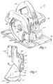
Fig. 1 is a perspective view of a circular saw
embodying the invention.
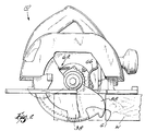
Fig. 2 is a side elevational view of the circular
saw shown in Fig. 1 with portions cut-away.
Fig. 3 is an enlarged, partial perspective view of
the circular saw shown in Fig. 1 with portions cut-away
to more clearly illustrate the blade guard stop.
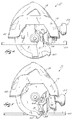
Fig. 4 is a side elevational view of the circular
saw and the blade guard stop, showing the shoe adjusted
for a maximum depth of cut.
Fig. 5 is a side elevational view of the circular
saw and the blade guard stop, showing the shoe adjusted
to a minimum depth of cut.
Before one embodiment of the invention is
explained in detail, it is to be understood that the
invention is not limited in its application to the
details of the construction and the arrangements of the
components set forth in the following description or
illustrated in the drawings. The invention is capable
of other embodiments and of being practiced or being
carried out in various ways. Also, it is understood
that the phraseology and terminology used herein is for
the purpose of description and should not be regarded
as limiting.
DETAILED DESCRIPTION OF THE PREFERRED EMBODIMENT
A circular saw 10 embodying the invention is
illustrated in Fig. 1. The circular saw 10 includes a
housing 14 having an operator's handle 18. An electric
motor (not shown) is supported by the housing 14. As
is commonly known in the art, the motor is selectively
connected to a power source (not shown) by a switch
(not shown). The motor drives a shaft 30 having a
rotational axis 34. The circular saw 10 also includes
a saw blade 38 supported on the drive shaft 30 and
driven by the motor for rotation about the axis 34. A
portion of the housing 14 serves as a fixed blade guard
42 covering the upper portion of the saw blade 38.
The housing 14 also includes a shoe plate 46
supported by the housing 14. The shoe plate 46
includes an opening 50 through which a portion of the
saw blade 38 extends. The shoe plate 46 is adjustable
relative to the housing 14 and relative to the axis 34
to vary the depth of cut (see Figs. 4 and 5) and bevel
angle of the saw blade 38. An adjustment mechanism 54
is operable to adjust the shoe plate 46, as described
more fully below.
The circular saw 10 also includes (see Fig. 2) a
rotatable lower blade guard 58. The blade guard 58 is
supported by the housing 14 for rotation about the axis
34 and generally in a plane defined by the blade
guard 58. The blade guard 58 is rotatable between a
first or uncovered position (shown in phantom in Fig.
2), in which the lower portion of the saw blade 38 is
exposed to cut a workpiece W, and a second or covered
position (shown in solid lines in Fig. 2), in which the
lower portion of the saw blade 38 is covered.
The blade guard 58 includes (see Fig. 3) a planar
portion 59 that is substantially parallel to the saw
blade 38 and that defines the plane in which the blade
guard 58 rotates. The blade guard 58 also includes an
annular L-shaped portion 60 extending from the planar
portion 59 and covering a portion of the teeth of the
saw blade 38. A workpiece engaging portion 61 extends
from the L-shaped portion 60 and is engageable with the
workpiece W. The blade guard 58 is constructed of a
low friction material such as aluminum.
The circular saw 10 also includes (see Fig. 2) a
biasing member 62 connected to the blade guard 58. The
biasing member 62 applies a biasing force to rotate the
blade guard 58 toward the covered position. In the
illustrated construction, the biasing member 62 is a
spring connected between the housing 14 and the blade
guard 58.
The circular saw 10 also includes (see Fig. 3) an
elongated, flexible, impact absorbing spring member 66
supported by the housing 14. The spring member 66
absorbs the rotational force of the blade guard 58 as
the blade guard 58 moves from the uncovered position
(shown in phantom in Fig. 2) to the covered position
(shown in solid lines in Fig. 2). The spring member 66
stops the blade guard 58 in the covered position and
thereby prevents rotation of the blade guard 58 beyond
the covered position. Whenever the blade guard 58
engages the spring member 66, the spring member 66
counteracts the biasing force of the biasing member 62.
The spring member 66 is (see Fig. 3) an integrally
formed one-piece member and includes a body portion 70.
The body portion 70 is elongated and flexible and
includes upper and lower end portions 71 and 72. A
flexible stop portion 74 extends from end portion 72.
The stop portion 74 is generally rounded or circular
and includes a smooth, arcuate engaging surface 75.
Both the body portion 70 and the stop portion 74 flex
to absorb the rotational force of the blade guard 58
and the biasing force of the biasing member 62.
The spring member 66 also includes a mounting
portion 78 connected to the end portion 71. The
mounting portion 78 is connected to the housing 14 in a
suitable manner, such as by riveting, welding, or the
use of screws, so that the spring member 66 is
supported by the housing 14. In the illustrated
construction, the mounting portion 78 is connected by
rivets or fasteners 82 to the adjustment mechanism 54
of the shoe plate 46 so that the spring member 66 is
movable with the shoe plate 46 when the shoe plate 46
is adjusted.
In the illustrated construction, the spring member
66 is a leaf spring and is constructed of a low
friction material such as steel. Also, the spring
member 66 is oriented so that the body portion 70 and
the stop portion are substantially in the rotational
plane of the blade guard 58.
In operation, the circular saw 10 is placed
against the surface of the workpiece W. The operator
engages the motor to drive the saw blade 38. As shown
in Fig. 2 in the change of position from solid lines to
phantom, as the operator moves the circular saw 10
across the surface of the workpiece W, the workpiece
engaging portion 61 of the blade guard 58 engages an
edge of the workpiece W, causing the blade guard 58 to
rotate from the covered position to the uncovered
position. The saw blade 38 is thus exposed as it cuts
through the workpiece W. The force of the workpiece W
on the blade guard 58 overcomes the biasing force of
the biasing member 62 and causes the blade guard 58 to
move to the uncovered position.
Once the operator has completed cutting the
workpiece W and the workpiece engaging portion 61 of
the blade guard 58 is no longer engaging the workpiece
W, the biasing force of the biasing member 62 causes
the blade guard 58 to rotate from the uncovered
position to the covered position. As the blade guard
58 reaches the covered position, the engaging surface
of the blade guard 58 impacts the engaging surface 75
of the spring member 66 causing the stop portion 74 and
the body portion 70 to flex and absorb the impact of
the blade guard 58 and to absorb the biasing force of
the biasing member 62. Once the rotational force of
the blade guard 58 has been absorbed, the body portion
70 and the stop portion 74 continue to apply a constant
biasing force to the blade guard 58 to counteract the
biasing force of the biasing member 62.
As shown in Figs. 4 and 5, the illustrated
circular saw 10 is a drop shoe and pivot shoe circular
saw. The shoe plate 46 is adjustable relative to the
housing 14 and relative to the saw blade 38 to adjust
the cutting depth of the saw blade 38 and the bevel
angle of the saw blade 38. Normally, the shoe plate 46
is adjusted when the blade guard 58 is in the covered
position contacting the spring member 66. As the shoe
plate 46 is adjusted, the blade guard 58 moves against
the surface of the stop portion 74. Because the blade
guard 58 and the spring member 66 are constructed of a
low friction material, friction between the blade guard
58 and the spring member 66 is greatly reduced.
As shown in Figs. 4 and 5, the shoe plate 46 is
adjustable to change the depth of cut of the saw blade
38. As shown in Fig. 4, with the shoe plate 46
adjusted to a first depth position, in this case a
maximum depth of cut for the saw blade 38, the blade
guard 58 engages a first portion of the spring member
66 in a first direction having a generally upward or
vertical vector component, illustrated by arrow "A".
As shown in Fig. 5, with the shoe plate 46 adjusted to
second depth position, in this case a minimum depth of
cut for the saw blade 38, the blade guard 58 engages a
second portion of the spring member 66 in a second
direction having a generally horizontal vector
component, illustrated by arrow "B". With the blade
guard 58 in any intermediate position between the
maximum depth of cut position (shown in Fig. 4) or the
minimum depth of cut position (shown in Fig. 5), the
blade guard 58 engages another portion of the spring
member 66 in a direction having a vector component that
is between horizontal and vertical. This vector
component depends on the position of the shoe plate 46
and the curvature of the engaging surface of the blade
guard 58. Regardless of the position, the spring
member 66 absorbs the rotational force of the blade
guard 58 and the biasing force of the biasing member 62
from both the first direction and the second direction.
In comparison testing conducted between the above-described
prior art blade guard stop and the spring
member 66 of the present invention, it was found that
the spring member 66 has a useful life that is
approximately four times the useful life of the prior
art blade guard stop member.
As shown in Table 1, on average, the prior art
blade guard stop member assembly failed after
approximately 84,600 cycles or impacts by a rotatable
lower blade guard. Because the prior art blade guard
stop experiences two failures (the rubber bumper and
the fastener each fail), the mean time between failure
of a component of the prior art blade guard stop member
is approximately 42,300 cycles.
In comparison, as shown in Table 2, on average,
the
spring member 66 did not fail until more than
332,700 impacts by the
blade guard 58.
| Prior Art Blade Guard Stop Member | Rubber Bumper Cracking (cycles) | Rubber Bumper Failure (cycles) | Fastener Failure (cycles) |
| #1 | 7,200 | 21,600 | 72,000 |
| #2 | 12,600 | 39,600 | 97,200 |
| Average | 9,900 | 30,600 | 84,600 |
| Mean Time Between Failure | | | 42,300 |
| Spring Member | Failure (cycles) |
| #1 | 332,100 (no failure) |
| #2 | 302,400 (spring failure) |
| #3 | 363,600 (no failure) |
| Average and Mean Time Between Failure | 332,700 |
Various features of the invention are set forth in
the following claims.