EP0886876B1 - Elektrischer schalter - Google Patents
Elektrischer schalter Download PDFInfo
- Publication number
- EP0886876B1 EP0886876B1 EP97918021A EP97918021A EP0886876B1 EP 0886876 B1 EP0886876 B1 EP 0886876B1 EP 97918021 A EP97918021 A EP 97918021A EP 97918021 A EP97918021 A EP 97918021A EP 0886876 B1 EP0886876 B1 EP 0886876B1
- Authority
- EP
- European Patent Office
- Prior art keywords
- housing
- connection
- contact
- electrical
- actuating element
- Prior art date
- Legal status (The legal status is an assumption and is not a legal conclusion. Google has not performed a legal analysis and makes no representation as to the accuracy of the status listed.)
- Expired - Lifetime
Links
- 239000003990 capacitor Substances 0.000 claims description 38
- 239000004065 semiconductor Substances 0.000 claims description 19
- RYGMFSIKBFXOCR-UHFFFAOYSA-N Copper Chemical compound [Cu] RYGMFSIKBFXOCR-UHFFFAOYSA-N 0.000 claims description 9
- 229910052802 copper Inorganic materials 0.000 claims description 9
- 239000010949 copper Substances 0.000 claims description 9
- 230000006835 compression Effects 0.000 claims description 7
- 238000007906 compression Methods 0.000 claims description 7
- 238000004804 winding Methods 0.000 claims description 7
- 229910001369 Brass Inorganic materials 0.000 claims description 5
- 239000010951 brass Substances 0.000 claims description 5
- 229910000906 Bronze Inorganic materials 0.000 claims description 3
- DMFGNRRURHSENX-UHFFFAOYSA-N beryllium copper Chemical compound [Be].[Cu] DMFGNRRURHSENX-UHFFFAOYSA-N 0.000 claims description 3
- 239000010974 bronze Substances 0.000 claims description 3
- 239000000919 ceramic Substances 0.000 claims description 3
- KUNSUQLRTQLHQQ-UHFFFAOYSA-N copper tin Chemical compound [Cu].[Sn] KUNSUQLRTQLHQQ-UHFFFAOYSA-N 0.000 claims description 3
- 229910052751 metal Inorganic materials 0.000 claims description 3
- 239000002184 metal Substances 0.000 claims description 3
- 239000007787 solid Substances 0.000 claims description 3
- 239000004033 plastic Substances 0.000 claims description 2
- 230000003213 activating effect Effects 0.000 claims 1
- 238000001816 cooling Methods 0.000 claims 1
- 230000001629 suppression Effects 0.000 description 29
- 210000003746 feather Anatomy 0.000 description 3
- 238000009434 installation Methods 0.000 description 3
- 238000005457 optimization Methods 0.000 description 3
- 230000000149 penetrating effect Effects 0.000 description 3
- 238000010586 diagram Methods 0.000 description 2
- 238000002347 injection Methods 0.000 description 2
- 239000007924 injection Substances 0.000 description 2
- 239000004952 Polyamide Substances 0.000 description 1
- 238000010276 construction Methods 0.000 description 1
- 239000003365 glass fiber Substances 0.000 description 1
- 230000010354 integration Effects 0.000 description 1
- 238000004519 manufacturing process Methods 0.000 description 1
- 239000000463 material Substances 0.000 description 1
- 150000002739 metals Chemical class 0.000 description 1
- 229920002647 polyamide Polymers 0.000 description 1
- 230000001105 regulatory effect Effects 0.000 description 1
- 239000000243 solution Substances 0.000 description 1
- 239000000725 suspension Substances 0.000 description 1
Images






Classifications
-
- H—ELECTRICITY
- H01—ELECTRIC ELEMENTS
- H01H—ELECTRIC SWITCHES; RELAYS; SELECTORS; EMERGENCY PROTECTIVE DEVICES
- H01H9/00—Details of switching devices, not covered by groups H01H1/00 - H01H7/00
- H01H9/02—Bases, casings, or covers
- H01H9/06—Casing of switch constituted by a handle serving a purpose other than the actuation of the switch, e.g. by the handle of a vacuum cleaner
- H01H9/061—Casing of switch constituted by a handle serving a purpose other than the actuation of the switch, e.g. by the handle of a vacuum cleaner enclosing a continuously variable impedance
-
- H—ELECTRICITY
- H02—GENERATION; CONVERSION OR DISTRIBUTION OF ELECTRIC POWER
- H02K—DYNAMO-ELECTRIC MACHINES
- H02K11/00—Structural association of dynamo-electric machines with electric components or with devices for shielding, monitoring or protection
- H02K11/40—Structural association with grounding devices
-
- H—ELECTRICITY
- H01—ELECTRIC ELEMENTS
- H01H—ELECTRIC SWITCHES; RELAYS; SELECTORS; EMERGENCY PROTECTIVE DEVICES
- H01H1/00—Contacts
- H01H1/58—Electric connections to or between contacts; Terminals
- H01H1/5833—Electric connections to or between contacts; Terminals comprising an articulating, sliding or rolling contact between movable contact and terminal
-
- H—ELECTRICITY
- H01—ELECTRIC ELEMENTS
- H01H—ELECTRIC SWITCHES; RELAYS; SELECTORS; EMERGENCY PROTECTIVE DEVICES
- H01H1/00—Contacts
- H01H1/58—Electric connections to or between contacts; Terminals
- H01H1/5866—Electric connections to or between contacts; Terminals characterised by the use of a plug and socket connector
-
- H—ELECTRICITY
- H01—ELECTRIC ELEMENTS
- H01H—ELECTRIC SWITCHES; RELAYS; SELECTORS; EMERGENCY PROTECTIVE DEVICES
- H01H9/00—Details of switching devices, not covered by groups H01H1/00 - H01H7/00
- H01H9/52—Cooling of switch parts
-
- Y—GENERAL TAGGING OF NEW TECHNOLOGICAL DEVELOPMENTS; GENERAL TAGGING OF CROSS-SECTIONAL TECHNOLOGIES SPANNING OVER SEVERAL SECTIONS OF THE IPC; TECHNICAL SUBJECTS COVERED BY FORMER USPC CROSS-REFERENCE ART COLLECTIONS [XRACs] AND DIGESTS
- Y10—TECHNICAL SUBJECTS COVERED BY FORMER USPC
- Y10S—TECHNICAL SUBJECTS COVERED BY FORMER USPC CROSS-REFERENCE ART COLLECTIONS [XRACs] AND DIGESTS
- Y10S388/00—Electricity: motor control systems
- Y10S388/935—Specific application:
- Y10S388/937—Hand tool
Definitions
- the invention relates to an electrical switch according to the Preamble of claim 1.
- Such electrical switches are used for switching on and off of electrical equipment from a voltage source be supplied.
- such switches are in Power tools used with an electric motor.
- the switch can also control electronics included, so that in addition to turning the Electric motor also the speed of the electric motor according to a specifiable setpoint by the switch is adjustable.
- DE-A1-28 38 934 describes an electrical switch for and switching off and setting the speed for one Electric motor known.
- the switch has a housing with two input connections on or in the housing for electrical connection to the voltage source and two Output connections for electrical connection to the Electric motor.
- the switch contact is again as a contact rocker with two lever arms and one Swivel bearing designed, the one with the fixed contact cooperating, first lever arm by a spring force in Closing direction for fixed contact is loaded.
- On the housing there is a manually movable push button Actuator.
- the actuator acts on it Movement on the second lever arm at the switching contact of the respective contact system that the first lever arm for Close the electrical connection of the contact system to the Fixed contact can be created.
- the actuator also acts the control electronics together, so that of the control electronics a speed corresponding to the position of the actuator is adjustable on the electric motor.
- Another electrical switch for switching on and off and for setting the speed for an electric motor known from DE-C2-40 38 787.
- this switch In the housing of this switch there are two contact systems, each consisting of two Fixed contacts and a spring-loaded contact bridge, as well as control electronics.
- the first fixed contact is on one contact track connected to an input port and the second fixed contact on one in connection with the Control electronics standing contact angle arranged.
- the Contact bridge is from the actuator via a switch cam to close the electrical connection of the contact system the two fixed contacts are created.
- the contact system of this Switch is sensitive to tolerances and also requires assembly.
- EP-A-0 512 316 is a switch for a Cordless power tool known.
- This switch has an in Control electronics with a housing associated power transistor for speed control of a Electric motor.
- At the bottom of the case are input connections arranged with a battery in electrical contact.
- One of the input ports is connected to a contact rail in the housing, the along a housing wall through the housing to the switch runs.
- the other input connector is with a Contact carrier connected to another housing wall leads two contact systems.
- a bearing plate is arranged, which has a bolt that serves, among other things, as a connection to the power transistor.
- the switch contact of the upper contact system is also on Bearing plate arranged. Another approach leads from the bearing plate as an electrical connection element to the switch.
- the invention is based on EP-A-0 512 316 Task based on an electrical switch like this to further develop that with the same or increased Functionality a reduction in the installation space required is achieved.
- the inventive solution according to claim 1 includes in essential a special current in the switch, whereby the switch housing can be made smaller.
- a power rail arranged in about The middle of the case runs and the case in the transverse direction or approximately perpendicular to the direction of movement of the Actuator penetrated.
- the current guide rail takes the pivot bearing for the switch contact of the contact system.
- the current guide rail also serves as mechanical bearing part for the switch contact and as electrical connection in the housing of the switch, which makes Housing can be made much more compact.
- the Power rail is an electrical connection to first output connector, but no direct electrical Connection to the first input port.
- the Fixed contact of the contact system with the first input connection in direct electrical connection and the second Input connection has an electrical connection part to second output connector.
- the switch according to the invention on a mains AC voltage operated, hand-held power tool used so that the input connections are the mains connection and the output connections around the field connections for the Field winding of the electric motor is acting.
- claim 11 includes in essential a special design of the Interior of the housing, so that a smaller housing for the Switch results.
- There are two inside the case Contact systems so these two contact systems are on opposite sides of the axis of the Actuator and essentially in the transverse direction in Arranged interior of the housing, the transverse direction to the Longitudinal direction corresponding to the direction of movement of the Actuator approximately vertical, in the plane of the axis of the actuator running direction.
- the Length of the interior of the housing in the longitudinal direction corresponds approximately the length of the switch contact.
- the depth direction the both is approximately perpendicular to the longitudinal and transverse directions, running depth of the housing interior is slightly larger than the width of the switch contact plus the width of any additional contained inside the housing electrical components.
- the depth is preferably approximately up to three times the width of the switch contact.
- the first lever arm of the switch contact is through a Compression spring or the like in the closing direction to the fixed contact charged.
- a cam on an axis leading into the housing the actuator acts on the second lever arm in this way a that the switch contact at a certain Movement path of the actuator on the fixed contact.
- Control electronics with a power semiconductor such as one Triac, FET or the like, for adjusting the speed of the electric motor are located, then one of the power rail electrical connection to the control electronics.
- a contact system is used to bridge the Control electronics.
- An electrical connection leads from the Control electronics for the fixed contact of the further contact system.
- the further contact system has a second, as Contact rocker trained switch contact, the pivot bearing on the power rail near the first one Output connector is located.
- the two switch contacts on the power rail are each other in the transverse direction arranged opposite each other.
- the contact spring For the electrical connection of the control electronics with the Current guide rail and with the fixed contact of the further Contact systems are used for contact springs that are resilient rest on a contact surface on the circuit carrier.
- the contact spring has an approximately heart-shaped, laterally open form.
- the contact spring is on an approach Fixed contact of the further contact system or Power guide rail, easily rotatable if necessary attached.
- the contact spring by means of a U-shaped part attached to the neck and for example caulking the neck with a certain play or be locked.
- the housing of the switch itself can accommodate the Interference suppression capacitor can be provided. This is at the beginning of the Power rail one between the two Input connections extending first Molded connection for the interference suppression capacitor and a second Connection for the interference suppression capacitor is with the second Input connection in electrical connection.
- the connections for the interference suppression capacitor in Art a plug connection.
- the one with the first input connection in Connected fixed contact of the first contact system integrally formed with the first input terminal.
- the input connections as a solid block-shaped part with a holder for the supply line to the voltage source be designed, the to attach the lead Recording can have a screw connection.
- An area of the block-shaped part at the first input connection forms the Fixed contact.
- the electrical connector on the second Input connector consists of a U-shaped on the second input connector plugged connector.
- spring legs are so that the U-shaped Connection part with a contact pressure on the block-shaped part of the second input connection is present.
- the U-shaped Connection part also has a connection lug, which as second output connection is used.
- U-shaped connector the second connector for the Interference suppression capacitor molded on. It is then expedient U-shaped connector with the terminal lug and the second Connection for the interference suppression capacitor formed in one piece.
- the fixed contact for the further contact system can also with a connector tab, which is the first output connector serves to be provided. It is also a good idea here To form a fixed contact and the connecting lug in one piece.
- the current guide rail, the input connections, the Output connections, the U-shaped connecting part and the other live parts are made of materials with good electrical conductivity, such as copper, brass or other metals.
- the current guide rail and the first copper input connector, the second Input connection and the U-shaped connection part made of brass and the contact spring to the circuit carrier made of bronze, Beryllium copper or the like exist.
- the housing continues to be like this designed that the transverse width of the The interior of the housing is essentially the sum of the heights of the two Contact systems and the diameter of the axis of the Actuator corresponds.
- the diameter of the Axis of the actuator can also be the height of one located on this axis, to act on the Contact systems serving sled be relevant. If necessary, the amount of the input and / or Output connection if this is also in the Are arranged inside the housing.
- the housing is in one piece the longitudinal and transverse direction in one plane Split base and cover.
- the base is for mounting of the contact systems and one as an electrical line current guiding rail between the contact systems and optionally the carriage or the axis of the Actuator provided.
- Can in the base or in the lid a guide and hold down for the sled are arranged his.
- Guide running parallel to the axis of the actuator be located. The actuator overlaps this Guidance, so that in the longitudinal direction a more compact arrangement of the actuator on the housing is possible.
- the circuit carrier for the control electronics is in one spanned by the longitudinal and transverse directions, parallel to Axis of the actuator level in the housing arranged such that one located on the carriage Grinder in contact with a potentiometer track on the Circuit carrier stands. This is on the potentiometer track a corresponding to the position of the actuator Removable voltage value, which in turn from the Control electronics as setpoint for the speed to be set is used.
- the power semiconductor is unhoused, directly on the Circuit carrier arranged, for example on the Circuit carrier soldered, which makes the otherwise considerable application height of a housing for the power semiconductor not applicable.
- the power semiconductor and the component side of the circuit carrier are facing the switch contacts, and the circuit carrier is direct or via a heat sink, like a copper plate or the like, with its the Component side opposite to a wall in the Interior of the housing, for example in the lid.
- To limit by means of the actuator adjustable speed can be a control wheel on the actuator for the adjustment of a cooperating with the housing Stop that the movement path of the actuator limited, be arranged.
- To lock the Actuator in certain movement positions can further a and held on the actuator locking slide on the outside of the housing with interact with a locking button.
- the locking slide is adjustable by means of the adjusting wheel and carries on the Adjustment wheel assigned side the stop.
- the locking button is in a dome located on the outside of the housing so against a arranged in the cathedral, in the locking button immersing spring movable that the locking button fully in Cathedral is retractable. This allows the height of the cathedral and consequently further reduce the depth of the housing.
- the axis of the setting wheel is offset transversely to the axis of the Actuator.
- the locking slide is also in Transversely and possibly offset in the depth direction arranged to the axis of the actuator. This arrangement of the adjusting wheel and the locking slide in contrast to conventional switches in turn allow a compact Design of the
- a holder for the Interference suppression capacitor are located, the inclusion in Transverse direction on the side where the input connections are for the switch, connects to the housing in such a way that the interference suppression associated connections on one of the Contact the input connections and the power rail can.
- the recording preferably consists of two parts, which in particular in one piece with the base and the lid are trained. There may be another in the recording Clearance to the outside of the housing for one Grounding the interference suppression capacitor.
- the strain relief for the power cord directly on Attach housing.
- the strain relief is on in the transverse direction the side on which the input connections are located, or if necessary, on the receptacle for the interference suppression capacitor arranged.
- the strain relief is preferably in one piece in integrated the base of the housing and consists of a Cable holder with a protruding web and one in the Web hung, screwed to the cable holder Clamp, with power cord with different diameters can be included.
- the clamp is already on one side of the cable holder injection molded a predetermined breaking point, so that the clamp at the Assembly of the cable canceled and to complete the Strain relief can be hung in the web.
- the length of the housing interior between 18 and 25 mm, the width of the housing inside between 30 and 40 mm, and the depth of the housing inside between 10 and 20 mm.
- the housing for the interference suppression capacitor there is a holder on the housing for the interference suppression capacitor, this can have a length between 20 and 35 mm and a width between 15 and 30 mm exhibit.
- a strain relief on the housing arranged it has a length between 20 and 30 mm and a width between 10 and 20 mm.
- an optimization of the Current flow in the housing of the electrical switch and / or achieved an optimization of the housing design so that the The switch housing is a compact and slim Can have design. Especially when a thumbwheel and a lock on the switch are provided Housing can still be kept compact.
- the switch is on a hand-held power tool used, so can due to the reduced installation space for the switch the handle of the power tool is slimmer than before be designed, what the ergonomics of the power tool increases.
- Further advantages achieved with the invention consist in that a reduction in the number of parts Switch is achieved, especially if the Input connection in one piece with the fixed contact of the Contact system, the output connection in one piece with the Fixed contact of the further contact system, etc. is formed and the strain relief is integrated on the housing.
- a further optimization of the current routing and reduction of The number of parts is due to the integration of the interference suppression capacitor achieved in the switch, as this would otherwise be necessary There is no wiring.
- the reduction in the number of parts pulls again a simplification of assembly and a total of one The switch becomes cheaper.
- the optimized current flow in the switch also to increase the Functional reliability of the switch.
- the wiring in the power tool is also simplified self.
- the electrical switch 1 is in one electrical device used by a voltage source is supplied.
- the electrical switch is preferably used 1 in a power tool, such as a drill, one Hammer drill or the like, used.
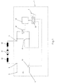
- Fig. 1 that is Block diagram for the arrangement of the electrical Switch 1 in a power tool by the Mains AC voltage U is supplied, shown in more detail.
- the power tool also has an electric motor 61 Field windings 62.
- the electric motor 61 is actuated the switch 1, which is in the handle of the power tool located, switched on and off by the user as well as his Speed set using switch 1.
- the switch 1 has a formed as a pusher Actuator 7, which is based on two contact systems 10, 11 and a potentiometer track 50 acts.
- the speed setting of the electric motor 61 takes place by means of control electronics 63 with a power semiconductor 22, such as a triac or the like, which are designed in the manner of a phase control is.
- By moving the actuator 7 is first Contact system 10 closed and the AC line voltage U via the power semiconductor 22 to the electric motor 61 placed.
- One of the position of the actuator 7 corresponding control voltage is from the potentiometer track 50 removed and fed to the control electronics 63.
- the Control electronics 63 ignite as a function of this control voltage the power semiconductor 22 at corresponding phase or current flow angle of Mains AC voltage U, so that ultimately the position of the actuator 7 corresponding speed of the Electric motor 61 set and regulated if necessary becomes.
- the actuator 7 is in its Maximum position, the contact system 11 is closed, whereby the control electronics 63 and the power semiconductor 22 can be bridged. So that's the full one Mains AC voltage U on the electric motor 61 and this moves yourself at the maximum speed.
- the switch 1 has for receiving the electrical Components such as the contact systems 10, 11 u.
- a Housing 2 as shown in more detail in Fig. 2.
- On the housing 2 are electrical input connections 3, 4 to Connection of the switch 1 to the AC line voltage U and Output connections 5, 6 for connecting the switch 1 with the field windings 62 of the electric motor 61.
- Die Input connections 3, 4 thus serve as the mains connection and Output connections 5, 6 as field connection.
- the Actuator 7 is on a leading into the housing 2 Axis 8 attached and is manually opposed by the user a restoring force, for example from one to the Axis 8 acting compression spring is generated, movable the actuator 7 as it moves to Contact systems 10, 11 acts.
- Contact systems 10, 11 each consist of a fixed contact 12, 13 and a switch contact 14, 15.
- the switch contact 14, 15 is a rotatably mounted contact rocker with two Lever arms formed and by the spring force of one Compression spring 43 in the closing direction to the fixed contact 12, 13 loaded by the compression spring 43 on the first, with the Fixed contact 12, 13 cooperating lever arm is arranged.
- the cam 44 acts on the second lever arm of the switching contact 14, 15 that the first lever arm of the switching contact 14, 15 at a certain Path of movement of the actuator 7 on the respective Fixed contact 12, 13 creates, with which the electrical connection of the respective contact system 10, 11 is closed.
- the two contact systems 10, 11 are also on the opposite sides of the Axis 8 of the actuator 7 arranged such that it essentially in the transverse direction in the interior 16 are on top of each other.
- the current flow in the electrical Switch 1 for this arrangement of the contact systems 10, 11 is can also be seen in more detail in FIG. 2.
- the fixed contact 12 of the contact system 10 is in contact with the first Input connection 3 in direct electrical connection.
- the second input connection 4 has a housing 2 arranged electrical connection part 17 to the second Output connector 6.
- the Input connections 3, 4 as a solid block-shaped part a receptacle 38 for the respective lead of the power cord educated.
- the receptacle 38 in turn has one Screw connection 39 for fastening the supply line.
- the Fixed contact 12 is in one piece with the first input connection 3 trained and integrated into the input port by the top surface on the block-shaped part of the first Input terminal 3 itself forms the fixed contact 12. Alternatively, it is also possible to have a pre-made contact to be attached to this surface.
- the block-shaped parts for the input connections 3, 4 can be made of copper, brass or Like. Be manufactured.
- the electrical Connecting part 17 at the second input terminal 4 made of a U-shaped Connecting part 40, as can be seen in FIGS. 6 and 14, that on the block-shaped part of the second Input connector 4 is plugged.
- the U-shaped connecting part 40 spring legs 41, which from the U-shaped connector 40 are cut out, as from 7 can be seen, so that the U-shaped connecting part 40th with a certain contact pressure at the input connection 4.
- the connecting part 40 also has a housing 2 penetrating terminal lug 42, the second Output terminal 6 forms.
- the U-shaped connector 40 together with the connecting lug 42 can be in one piece Stamped and bent part, for example made of brass.
- the current guide rail 18 begins approximately in the area between the two input connections 3, 4 and ends approximately in the area of the first output connection 5, which essentially corresponds to the input connections 3, 4 opposite. This is on the current guide rail 18 Rotary bearing 19 of the switching contact 14 of the first contact system 10 in the manner of a cutting edge bearing near the Input connections 3, 4 arranged.
- the current guide rail 18 provides the electrical connection to the second Contact system 11 forth, the pivot bearing 20 of the Switch contact 15 also on the current rail 18 in is arranged in the vicinity of the first output terminal 5.
- the as a stamped and bent part, for example made of copper Current guide rail 18 is as an individual part in FIGS. 10 and 11 shown in more detail.
- the electrical is via the second contact system 11 Connection from the current guide rail 18 to the first Output terminal 5 when bridging the control electronics 63 manufactured.
- the fixed contact 13 for the further contact system 11 is with a connecting lug penetrating the housing 2 66, which serves as the first output terminal 5. How 8 and 9, in which the Fixed contact 13 is shown as a single part, the Fixed contact 13 and the connecting lug 66 in one piece as Stamped and bent part, for example made of copper.
- the second contact system 11 If the second contact system 11 is not closed, then the electrical connection from the current guide rail 18 to the first output terminal 5 via the power semiconductor 22 manufactured in the control electronics 63. For this there is from Fixed contact 13 of the contact system 11 an electrical Connection 24 and from the current guide rail 18 a electrical connection 23 to the control electronics 63.
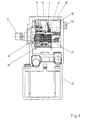
- Die Control electronics 63 is located on a circuit carrier 21, which is arranged in the housing 2, as can be seen in FIG. 4 is.
- the circuit carrier 21 can be a Act circuit board, a ceramic plate or the like.
- On the Circuit carrier 21 is still the Power semiconductor 22 and the potentiometer 50, with the one located on the carriage 9 and thus by the Actuator 7 movable grinder 49 is in contact.
- the electrical connections 23, 24 are advantageous formed as contact springs 45.
- the contact spring 45 has an approximately heart-shaped Shape, the side, the current guide rail 18 or one Approach 47 facing the fixed contact 13 is open.
- the contact spring 45 rests elastically on one Contact surface 46 on the circuit board 21.
- the Contact spring 45 can be made of bronze, beryllium copper or the like. consist. It lends itself to the contact spring 45 on one Approach 47 on the fixed contact 13 of the further contact system 11 or to fix the current guide rail 18. This Attachment takes place in such a way that the contact spring 45 on the neck 47 is easily rotatable.
- the contact spring 45 attached to the extension 47 by means of a U-shaped part 48 and providing some play with lug 47 be caulked.
- a receptacle 28 for an interference suppression capacitor 27 may be arranged on the housing 2, as can be seen in FIG. 2, a receptacle 28 for an interference suppression capacitor 27 may be arranged.
- the Recording 28 closes in the transverse direction according to arrow 65, on the side where the input connections 3, 4 are on the housing 2.
- To contact the Interference suppression capacitor 27 is at the beginning of the current-carrying rail 18 one between the two input connections 3, 4 extending extension formed as the first connection 25.
- a second connection 26 for the interference suppression capacitor 27 is available with the second input terminal 4 via the electrical Connection part 17 in connection.
- the connections 25, 26 for the suppression capacitor 27 are in the manner of a Plug connector formed so that the interference suppression capacitor 27 for assembly only in the receptacle 28 by plugging in is to be inserted at the connections 25, 26.
- forms the current guide rail 18 is a one-piece, common Bearing part with the pivot bearings 19, 20 for the switching contact 14 of the contact system 10 for the supply voltage, for the Switch contact 15 of the contact system 11 to bridge the Control electronics 63 and for connection 25 of the Interference suppression capacitor 27.
- On the U-shaped connecting part 40 as can be seen in FIGS. 6 and 7, also the second Connection 26 for the interference suppression capacitor 27 in one piece molded. You get a kind of base clamp for the Connection to the field winding 62 of the electric motor 61 via the terminal lug 42, to the interference suppression capacitor 27 and to the second input terminal 4 to the network.
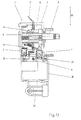
- Fig. 13 it is an on-off switch 1 ' without control electronics for a power tool. Since none Control electronics is available, the other is also omitted Contact system for bridging, so that 2 only the contact system 10 for switching the Supply voltage.
- the cross direction current guide rail 18 running according to arrow 65 is on the side of the contact system 10 opposite the Output terminal 5 'to field winding 62, for example as 10 and 11 shown, penetrating the housing 2 Terminal lug 73, integrally formed directly in one piece.
- the switch 1 ' is thus in essentially the same current flow inside the housing 16 as in the case of the switch 1 provided with control electronics 63 available.
- the housing 2 is in one the longitudinal and transverse directions according to arrows 64 and 65 of the Fig. 2 spanned parting plane in a base 29 and one Lid 30 divided.
- the dividing plane runs in the view 3 approximately along the line 4-4.
- the one in Fig. 2 Base 29 shown in more detail serves to accommodate the individual parts the switch 1, specifically the contact systems 10, 11, the input connections 3, 4, the output connections 5, 6 and the current guide rail 18.
- the cover 30 closes the base 29 and contains according to FIG. 4 the inside Circuit carrier 21, which in one by the longitudinal and Transverse direction spanned according to arrows 64, 65 and extending parallel to the axis 8 of the actuator 7 Level is arranged.
- a guide 59 for the slide is located in the base 29 9, for example in the manner of a groove and Spring connection, as shown in Fig. 3, one Dovetail or the like. Can be formed so that the Carriage 9 is held down in the base 29.
- the leadership 59 also represents an assembly aid, because the Guide 59 a falling out of the carriage 9 and the axis 8 is prevented from the base 29 during assembly. Is further through the guide 59 also the movability of the slide 9 improved since the tour through the facility on Cover 30 takes place.
- a Guide 59 together with the slide 9 and the axis 8 and optionally other electrical components instead of in Base 29 can be arranged in the cover 30.
- the base 29th or the cover 30 is on the outside of the base 29th or the cover 30 according to at least one in the longitudinal direction arrow 64 and parallel to axis 8 of actuator 7 extending guide surface 60 for the actuator 7 located.
- the actuator 7 engages over these guide surfaces 60, 60 ', so that when Movement of the actuator 7, these guide surfaces 60, 60 'immerse into the interior of the actuator 7. The contributes to the fact that in the longitudinal direction according to arrow 64 the expansion of the switch 1 is further reduced.
- the power semiconductor 22nd unhoused located directly on the circuit carrier 21, such as 4 can be seen in more detail.
- the power semiconductor 22 and the component side for are the electrical components 70 of the circuit carrier 21 facing the switch contacts 14, 15.
- With its the The opposite side is the component side Circuit carrier 21 directly on a wall 51 inside the housing 16, namely in the cover 30, as in particular from FIG. 3 emerges. If it is due to the power loss in the Power semiconductor 22 is necessary, the Circuit carrier 21 also via a heat sink, such as one Copper plate or the like, lie against the wall 51.
- the recording 28 for the interference suppression capacitor 27 from two halves, which in one by the longitudinal and transverse directions corresponding to the Arrows 64 and 65 spanned, in Fig. 3 also approximately divided along the cutting line 4-4 dividing plane are.
- the two halves are expediently in one piece formed with the base 29 and the lid 30.
- In the Recording 28 is located in the transverse direction according to the Arrow 65 running recess 31 to the outside of the Housing 2 through which an earth connection 32 or Potential center connection of the interference suppression capacitor 27 can protrude through.
- the housing 2 can be attached the receptacle 28 for the interference suppression capacitor 27 Connect strain relief 33, as can be seen in Fig. 2.
- the Strain relief 33 takes the power cord of the power tool that leads to the input connections 3, 4. If none Receptacle 28 is arranged for an interference suppression capacitor 27, can the strain relief 33 also directly on the housing 2 Connect on the side where the input connections are 3, 4 are located.
- the strain relief 33 consists of a Cable receptacle 34 with a projecting web 35 and one in the web 35 hooked clamp 36.
- the clamp 36 is by means of a screw 37 on the cable receptacle 34 attachable.
- the clamp 36 can have two surfaces different Have curvature, with a surface straight can be trained. By rotating the clamp 36 by 180 Power cord of different diameters in the degree Strain relief 33 are added.
- the clamp 36 is thus symmetrical in the area of the screw 37 and the protruding Bars 35 and asymmetrical in the clamping area for the power cord educated.
- the suspension of the clamp 36 in the web 35 in itself results in a certain game that the inclusion of Power cord with different diameters supported.
- the Cable receptacle 34 and the web 35 are expedient in one piece on the housing 2, preferably in the base 29 integrated.
- the strain relief 33 suitably exists made of the same plastic as the housing 2, for example made of glass fiber reinforced polyamide.
- the Base 29 can then clamp 36 with a predetermined breaking point 74 are injection molded onto one side of the cable receptacle 34, as shown in Fig. 15 so that when the switch is assembled 1 in the power tool, the clamp 36 broken off and after Attach the power cord to switch 1 to complete the Strain relief 33 hooked into the web 35 and on the Cable holder 34 can be attached.
- an adjusting wheel 52 with an im Actuator 7 rotatably mounted axis 54 is provided be, as shown in Fig. 2, with the help of a adjustable speed limit below the maximum possible speed of the electric motor 61 is made possible.
- Locking slide 55 held on the outside of the Housing 2 is guided and by turning the knob 52nd via a thread 71 in the longitudinal direction according to arrow 64 (see Fig. 2) is adjustable.
- At locking slide 55 is on the side associated with the adjusting wheel 52 Stop 53, which cooperates with the housing 2.
- Adjustment of the locking slide 55 becomes the stop 53 also adjusted and thus the movement path of the Actuator 7 to a smaller than the maximum possible adjustment path, which means that the Actuator 7 adjustable speed accordingly is limited.
- the actuator 7 is the largest adjustment according to the set speed limit lockable by a locking button 56 with the Locking slide 55 cooperates, as shown in more detail in FIG. 5 emerges.
- the locking button 56 is in one on the Outside of the housing 2 located dome 57 stored. in the Dom 57 is in turn in the locking button 56 immersed spring 58 against which the locking button 56 such it is movable that the locking button 56 is fully in the dome 57 is retractable.
- the recessed one reaches for locking Locking button 56 in a recess 72, which is shown in FIG can be seen in the locking slide 55.
- the adjusting wheel 52 is arranged such that its axis 54 in Transverse direction according to arrow 65 offset to axis 8 of the Actuating member 7 is, as in particular from FIG. 2 can be seen.
- the locking slide 55 is also in Transverse direction according to arrow 65 and possibly in Depth direction according to arrow 69 (see Fig. 3) offset to Axis 8 of the actuator 7 arranged as shown in FIGS. 2 and 5 emerges.
- Convention Power tool switches with one on the side of the housing The adjusting wheel and the locking slide are locked coaxial to the axis of the actuator.
- the electrical switch 1 according to the invention is, as already mentioned, particularly suitable for arrangement in one slim, ergonomically designed handle of one Power tool.
- information on the preferred dimensioning for the housing 2 of such Power tool switches are made accordingly 2 shows the housing 2 in the longitudinal direction according to arrow 64 running length 1, one in the transverse direction according to arrow 65 running width b and a corresponding to FIG. 3 in Depth direction depth t running according to arrow 69 owns.
- the length 1 of the housing interior 16 corresponds approximately to that Length of the switching contact 14, 15.
- the width b of the Housing interior 16 corresponds essentially to the sum of Heights of the two contact systems 10, 11 and the diameter the axis 8 of the actuator 7 or possibly the Height of the carriage 9 and, if necessary, the height of the Input connection 3, 4. If the output connection 5, 6 in Housing interior 16 is located, its height can still to come.
- the depth t of the housing interior 16 is slightly larger than the width of the switching contact 14, 15 plus the width of possibly inside the housing 16 contained additional electrical components, such as the Grinder 49 for the potentiometer track 50 and Circuit carrier 21.
- the depth t is preferably approximately up to three times the width of the switching contact 14, 15. Then come to length 1, width b and depth t of the housing 2 add the respective wall thicknesses for the housing 2.
- such a switch 1 can the length 1 of the housing interior 16 between 18 and 25 mm, in particular be approximately 21 mm.
- the width b of the Housing interior 16 can be between 30 and 40 mm, in particular approx. 33 mm.
- the depth t of the housing interior 16 again, between 10 and 20 mm, in particular about 13 mm chosen.
- the wall thicknesses for the housing 2 are between 0.5 and 4 mm.
- it may have on the housing 2 located receptacle 28 for the interference suppression capacitor 27 a Length 1 between 20 and 35 mm, especially about 27 mm as well a width b between 15 and 30 mm, in particular approximately 24 mm.
- Strain relief 33 has a length 1 between 20 and 30 mm, in particular about 24 mm, and a width b between 10 and 20 mm, in particular approx. 15 mm.
- the depths t for the recording 28 and the strain relief 33 can be somewhat lower if necessary be chosen as for the rest of the housing 2.
- the invention is not described and described illustrated embodiments limited. It includes rather, all professional training within the framework of the inventive concept.
- a switch not only on one operated with AC mains voltage Power tool but also on one with DC voltage operated battery electric tool can be used. In this Case is a FET, MOS-FET or the like as a power semiconductor. used.
- Such a switch can also be used in other electrical supplied by a voltage source Appliances such as garden tools, kitchen utensils or the like, use Find.
Landscapes
- Engineering & Computer Science (AREA)
- Power Engineering (AREA)
- Switch Cases, Indication, And Locking (AREA)
- Push-Button Switches (AREA)
- Mechanisms For Operating Contacts (AREA)
- Details Of Connecting Devices For Male And Female Coupling (AREA)
Description
- Fig. 1
- ein Prinzipschaltbild für die Anordnung des elektrischen Schalters in einem Elektrowerkzeug,
- Fig. 2
- einen Längsschnitt durch einen elektrischen Schalter für ein Elektrowerkzeug,
- Fig. 3
- einen Schnitt entlang der Linie 3-3 in Fig. 2,
- Fig. 4
- einen Schnitt entlang der Linie 4-4 in Fig. 3,
- Fig. 5
- einen Schnitt entlang der Linie 5-5 in Fig. 2,
- Fig. 6
- den zweiten Eingangsanschluß mit Anschlußteil als Einzelteil,
- Fig. 7
- das Anschlußteil gemäß Richtung VII aus Fig. 6,
- Fig. 8
- den ersten Ausgangsanschluß als Einzelteil,
- Fig. 9
- den ersten Ausgangsanschluß gemäß Richtung IX aus Fig. 8,
- Fig. 10
- die Stromführungsschiene als Einzelteil,
- Fig. 11
- die Stromführungsschiene gemäß Richtung XI aus Fig. 10,
- Fig. 12
- das Betätigungsorgan als Einzelteil, teilweise im Schnitt,
- Fig. 13
- einen Schalter wie in Fig. 2 in einer weiteren Ausführungsform,
- Fig. 14
- das Anschlußteil gemäß Richtung XIV aus Fig. 6 und
- Fig. 15
- einen Ausschnitt des Gehäuses im Bereich der Zugentlastung.
- 1,1':
- elektrischer Schalter
- 2:
- Gehäuse
- 3,4:
- Eingangsanschluß
- 5,6:
- Ausgangsanschluß
- 5':
- Ausgangsanschluß (weitere Ausführung)
- 7:
- Betätigungsorgan
- 8:
- Achse
- 9:
- Schlitten
- 10,11:
- Kontaktsystem
- 12,13:
- Festkontakt
- 14,15:
- Schaltkontakt
- 16:
- Gehäuseinneres
- 17:
- elektrisches Verbindungsteil
- 18:
- Stromführungsschiene
- 19,20:
- Drehlager (für Schaltkontakt)
- 21:
- Schaltungsträger
- 22:
- Leistungshalbleiter
- 23,24:
- elektrische Verbindung (zur Steuerelektronik)
- 25,26:
- Anschluß (für Entstörkondensator)
- 27:
- Entstörkondensator
- 28:
- Aufnahme (für Entstörkondensator)
- 29:
- Sockel
- 30:
- Deckel
- 31:
- Freisparung (für Erdungsanschluß)
- 32:
- Erdungsanschluß
- 33:
- Zugentlastung
- 34:
- Kabelaufnahme
- 35:
- Steg
- 36:
- Schelle
- 37:
- Schraube
- 38:
- Aufnahme (im Eingangsanschluß)
- 39:
- Schraubanschluß
- 40:
- U-förmiges Anschlußteil
- 41:
- Federschenkel
- 42:
- Anschlußfahne
- 43:
- Druckfeder
- 44:
- Nocken
- 45:
- Kontaktfeder
- 46:
- Kontaktfläche (an Schaltungsträger)
- 47:
- Ansatz
- 48:
- U-förmiges Teil (an Kontaktfeder)
- 49:
- Schleifer
- 50:
- Potentiometerbahn
- 51:
- Wand (des Gehäuses)
- 52:
- Stellrad
- 53:
- Anschlag
- 54:
- Achse (des Stellrades)
- 55:
- Arretierschieber
- 56:
- Arretierknopf
- 57:
- Dom
- 58:
- Feder (im Dom)
- 59:
- Führung
- 60,60':
- Führungsfläche
- 61:
- Elektromotor
- 62:
- Feldwicklung
- 63:
- Steuerelektronik
- 64:
- Pfeil (Längsrichtung)
- 65:
- Pfeil (Querrichtung)
- 66:
- Anschlußfahne (am ersten Ausgangsanschluß)
- 67:
- Federschenkel
- 68:
- Fenster
- 69:
- Pfeil (Tiefenrichtung)
- 70:
- elektrisches Bauteil (auf Schaltungsträger)
- 71:
- Gewinde (an Stellrad)
- 72:
- Ausnehmung (in Arretierschieber)
- 73:
- Anschlußfahne (am ersten Ausgangsanschluß, weitere Ausführung)
- 74:
- Sollbruchstelle (an Zugentlastung)
Claims (18)
- Elektrischer Schalter für ein von einer Spannungsquelle versorgtes elektrisches Gerät, insbesondere für ein Elektrowerkzeug mit einem Elektromotor (61), mit einem Gehäuse (2), mit zwei am und/oder im Gehäuse (2) befindlichen Eingangsanschlüssen (3, 4) zum elektrischen Anschluß an die Spannungsquelle und zwei Ausgangsanschlüssen (5, 5', 6) zum elektrischen Anschluß an das elektrische Gerät, mit einem vorzugsweise als Drücker ausgebildeten, manuell bewegbaren Betätigungsorgan (7), und mit wenigstens einem Kontaktsystem (10), das aus einem Festkontakt (12) sowie einem als Kontaktwippe ausgebildeten Schaltkontakt (14) besteht, wobei die Kontaktwippe zwei Hebelarme und ein Drehlager (19) besitzt, wobei der mit dem Festkontakt (12) zusammenwirkende, erste Hebelarm durch eine Federkraft in Schließrichtung zum Festkontakt (12) belastet ist, wobei das Betätigungsorgan (7) bei seiner Bewegung derart auf den zweiten Hebelarm einwirkt, daß der erste Hebelarm zum Schließen der elektrischen Verbindung des Kontaktsystems (10) an den Festkontakt (12) anlegbar ist, wobei der Festkontakt (12) des Kontaktsystems (10) mit dem ersten Eingangsanschluß (3) in direkter elektrischer Verbindung steht, wobei der zweite Eingangsanschluß (4) ein im und/oder am Gehäuse (2) angeordnetes elektrisches Verbindungsteil (17) zum zweiten Ausgangsanschluß (6) besitzt, und wobei eine im Gehäuse (2) befindliche Stromführungsschiene (18) eine elektrische Verbindung zum ersten Ausgangsanschluß (5, 5') herstellt, dadurch gekennzeichnet, daß die Stromführungsschiene (18) in etwa im Bereich zwischen den beiden Eingangsanschlüssen (3, 4) beginnt und in etwa im Bereich des ersten, den Eingangsanschlüssen (3, 4) gegenüberliegenden Ausgangsanschlusses (5, 5') endet, daß die Stromführungsschiene (18) das Gehäuse (2) in Querrichtung (65) zur Bewegungsrichtung des Betätigungsorgans (7) durchsetzend angeordnet ist, daß die Stromführungsschiene (18) in Längsrichtung (64) zur Bewegungsrichtung des Betätigungsorgans (7) in etwa im mittleren Bereich des Gehäuses (2) verläuft, und daß das Drehlager (19) des Schaltkontakts (14) an der Stromführungsschiene (18) in der Nähe der Eingangsanschlüsse (3, 4) angeordnet ist.
- Elektrischer Schalter nach Anspruch 1, dadurch gekennzeichnet, daß die elektrische Verbindung zwischen der Stromführungsschiene (18) und dem ersten Ausgangsanschluß (5, 5') mittels eines im Gehäuse (2) befindlichen, weiteren Kontaktsystems (11) über das Betätigungsorgan (7) schaltbar ist.
- Elektrischer Schalter nach Anspruch 1 oder 2, dadurch gekennzeichnet, daß im Gehäuse (2) eine gegebenenfalls auf einem Schaltungsträger (21) befindliche Steuerelektronik (63) mit einem Leistungshalbleiter (22), wie einem Triac, FET o. dgl., zur Drehzahleinstellung des Elektromotors (61) angeordnet ist, daß eine elektrische Verbindung (23) von der Stromführungsschiene (18) zur Steuerelektronik (63) führt, daß vorzugsweise das weitere Kontaktsystem (11), das insbesondere zur Überbrückung der Steuerelektronik (63) dient, einen zweiten, als Kontaktwippe mit zwei Hebelarmen ausgebildeten Schaltkontakt (15) besitzt, dessen Drehlager (20) an der Stromführungsschiene (18) in der Nähe des ersten Ausgangsanschlusses (5, 5') befindlich ist, wobei insbesondere die beiden Schaltkontakte (14, 15) an der Stromführungsschiene (18) einander in Querrrichtung (65) gegenüberliegend angeordnet sind.
- Elektrischer Schalter nach Anspruch 1, 2 oder 3, dadurch gekennzeichnet, daß am Beginn der Stromführungsschiene (18) eine zwischen den beiden Eingangsanschlüssen (3, 4) verlaufende Verlängerung als erster Anschluß (25) für einen Entstörkondensator (27), insbesondere einstückig angeformt ist, daß ein zweiter Anschluß (26) für den Entstörkondensator (27) vorzugsweise mit dem zweiten Eingangsanschluß (4) in elektrischer Verbindung steht, wobei die Anschlüsse (25, 26) für den Entstörkondensator (27) insbesondere in der Art eines Steckanschlusses ausgebildet sind, und daß gegebenenfalls an der dem Kontaktsystem (10) gegenüberliegenden Seite eine als erster Ausgangsanschluß (5') dienende Anschlußfahne (73), insbesondere einstückig am Ende der Stromführungsschiene (18) angeformt ist.
- Elektrischer Schalter nach einem der Ansprüche 1-4, dadurch gekennzeichnet, daß der Festkontakt (12) des Kontaktsystems (10) einstückig mit dem ersten Eingangsanschluß (3) ausgebildet ist, daß vorzugsweise das elektrische Verbindungsteil (17) am zweiten Eingangsanschluß (4) aus einem U-förmigen, auf den zweiten Eingangsanschluß (4), insbesondere mittels Federschenkel (41), aufgesteckten Anschlußteil (40) besteht, daß das Anschlußteil (40) weiter vorzugsweise eine Anschlußfahne (42), die als zweiter Ausgangsanschluß (6) dient, besitzt, und daß am Anschlußteil (40) noch weiter vorzugsweise der zweite Anschluß (26) für den Entstörkondensator (27) angeformt ist, wobei insbesondere das Anschlußteil (40) mit der Anschlußfahne (42) und dem zweiten Anschluß (26) für den Entstörkondensator (27) einstückig ausgebildet ist.
- Elektrischer Schalter nach einem der Ansprüche 1 bis 5, dadurch gekennzeichnet, daß der Festkontakt (13) für das weitere Kontaktsystem (11) mit einer Anschlußfahne (66), die als erster Ausgangsanschluß (5) dient, versehen ist, wobei insbesondere der Festkontakt (13) und die Anschlußfahne (66) einstückig ausgebildet sind, und daß vorzugsweise eine elektrische Verbindung (24) vom Festkontakt (13) des weiteren Kontaktsystems (11) zur Steuerelektronik (63) besteht.
- Elektrischer Schalter nach einem der Ansprüche 1 bis 6, dadurch gekennzeichnet, daß die elektrische Verbindung (23, 24) von der Steuerelektronik (63) zur Stromführungsschiene (18) sowie zum Festkontakt (13) des weiteren Kontaktsystems (11) als Kontaktfeder (45), die insbesondere eine ungefähr herzförmige, seitlich offene Gestalt besitzt, ausgebildet ist, wobei vorzugsweise die Kontaktfeder (45) elastisch federnd an einer Kontaktfläche (46) auf dem Schaltungsträger (21) anliegt und wobei weiter vorzugsweise die Kontaktfeder (45) an einem Ansatz (47) am Festkontakt (13) des weiteren Kontaktsystems (11) oder der Stromführungsschiene (18), gegebenenfalls leicht drehbar befestigt ist, indem die Kontaktfeder (45) insbesondere mittels eines U-förmigen Teils (48) am Ansatz (47) aufgesteckt und beispielsweise unter Vorsehen eines gewissen Spiels mit dem Ansatz (47) verstemmt, verrastet o. dgl. ist.
- Elektrischer Schalter nach einem der Ansprüche 1 bis 7, dadurch gekennzeichnet, daß der Eingangsanschluß (3, 4) als massives blockförmiges Teil mit einer Aufnahme (38), die gegebenenfalls einen Schraubanschluß (39) besitzt, für die Zuleitung zur Spannungsquelle ausgebildet ist, wobei insbesondere eine Fläche am ersten Eingangsanschluß (3) den Festkontakt (12) bildet, daß vorzugsweise die Eingangsanschlüsse (3, 4) sowie die Kontaktfedern (45) aus Metall mit guter elektrischer Leitfähigkeit bestehen, und daß weiter vorzugsweise die Stromführungsschiene (18), das Anschlußteil (40) sowie der Festkontakt (13), insbesondere als Stanzbiegeteil, aus Metall mit guter elektrischer Leitfähigkeit hergestellt sind, wobei insbesondere die Stromführungsschiene (18) und der erste Eingangsanschluß (3) aus Kupfer, der zweite Eingangsanschluß (4) sowie das Anschlußteil (40) aus Messing und die Kontaktfeder (45) zum Schaltungsträger (21) aus Bronze, Beryllium-Kupfer o. dgl. bestehen.
- Elektrischer Schalter nach einem der Ansprüche 1 bis 8, dadurch gekennzeichnet, daß es sich bei der Spannungsquelle um die Netzwechselspannung handelt, so daß der Eingangsanschluß (3, 4) als Netzanschluß und der Ausgangsanschluß (5, 5', 6) als Feldanschluß für die Feldwicklung (62) des Elektromotors (61) dienen.
- Elektrischer Schalter nach einem der Ansprüche 1 bis 9, dadurch gekennzeichnet, daß die auf den ersten Hebelarm des Schaltkontakts (14, 15) einwirkende Federkraft von einer Druckfeder (43) erzeugt ist, und daß vorzugsweise ein Nocken (44) an einer in das Gehäuse (2) führenden Achse (8) des Betätigungsorgans (7), gegebenenfalls an einem Schlitten (9) an der Achse (8), auf den zweiten Hebelarm derart einwirkt, daß sich der Schaltkontakt (14, 15) bei einem bestimmten Bewegungsweg des Betätigungsorgans (7) an den Festkontakt (12, 13) anlegt.
- Elektrischer Schalter, wobei das Gehäuseinnere (16) des Gehäuses (2) eine in Längsrichtung (64) entsprechend der Bewegungsrichtung der Achse (8) des Betätigungsorgans (7) verlaufende Länge (1), eine in Querrichtung (65) zur Längsrichtung (64) und in der Ebene der Achse (8) des Betätigungsorgans (7) verlaufende Breite (b) und eine sowohl senkrecht zur Längsrichtung (64) als auch Querrichtung (65) verlaufende Tiefe (t) besitzt, nach einem der Ansprüche 1 bis 10, dadurch gekennzeichnet, daß die Länge (1) des Gehäuseinneren (16) der Länge des Schaltkontakts (14, 15) entspricht, daß die Tiefe (t) des Gehäuseinneren (16) größer als die in Richtung der Tiefe (t) verlaufende Breite des Schaltkontakts (14, 15) zuzüglich der Breite von im Gehäuseinneren (16) enthaltenen zusätzlichen elektrischen Komponenten bis zur dreifachen Breite des Schaltkontakts (14, 15) ist, und daß die Breite (b) des Gehäuseinneren (16) der Summe der Höhen der beiden Kontaktsysteme (10, 11), des Durchmessers der Achse (8) des Betätigungsorgans (7) oder der Höhe eines an der Achse (8) des Betätigungsorgans (7), im Gehäuseinneren (16) befindlichen, zur Einwirkung auf die Kontaktsysteme (10, 11) dienenden Schlittens (9) sowie, falls im Gehäuse (2) angeordnet, der Höhe des Eingangsanschlusses (3, 4) und/oder Ausgangsanschlusses (5, 6) entspricht.
- Elektrischer Schalter nach einem der Ansprüche 1 bis 11, dadurch gekennzeichnet, daß zwei Kontaktsysteme (10, 11) auf einander gegenüberliegenden Seiten der Achse (8) des Betätigungsorgans (7) und im wesentlichen in Querrichtung (65) im Gehäuseinneren (16) angeordnet sind.
- Elektrischer Schalter nach einem der Ansprüche 1 bis 12, dadurch gekennzeichnet, daß das Gehäuse (2) in einer durch die Längsrichtung (64) und Querrichtung (65) aufgespannten Ebene in einen Sockel (29) und einen Deckel (30) geteilt ist, wobei der Sockel (29) zur Aufnahme der Kontaktsysteme (10, 11) und einer als elektrischen Leitung dienenden Stromführungsschiene (18) sowie gegebenenfalls des Schlittens (9) oder der Achse (8) des Betätigungsorgans (7) ausgebildet ist, daß vorzugsweise eine Führung (59) und Niederhaltung für den Schlitten (9) im Sockel (29) oder im Deckel (30) angeordnet ist, und daß weiter vorzugsweise an der Außenseite des Sockels (29) oder des Deckels (30) wenigstens eine in Längsrichtung (64), parallel zur Achse (8) des Betätigungsorgans (7) verlaufende Führungsfläche (60, 60') befindlich ist, wobei das Betätigungsorgan (7) die Führungsfläche (60, 60') übergreift.
- Elektrischer Schalter nach einem der Ansprüche 1 bis 13, dadurch gekennzeichnet, daß es sich beim Schaltungsträger (21) für die Steuerelektronik (63) um eine Leiterplatte, eine Keramikplatte o. dgl. handelt, daß vorzugsweise der Schaltungsträger (21) im Deckel (30) angeordnet ist, wobei der Schaltungsträger (21) insbesondere in einer durch die Längsrichtung (64) und Querrichtung (65) aufgespannten, parallel zur Achse (8) des Betätigungsorgans (7) verlaufenden Ebene derart angeordnet ist, daß ein am Schlitten (9) befindlicher Schleifer (49) in Kontakt mit einer Potentiometerbahn (50) auf dem Schaltungsträger (21) steht, daß weiter vorzugsweise der Leistungshalbleiter (22) ungehäust, direkt auf Schaltungsträger (21), beispielsweise mittels einer Lötverbindung befindlich ist, wobei der Leistungshalbleiter (22) und die Bestückungsseite des Schaltungsträgers (21) insbesondere den Schaltkontakten (14, 15) zugewandt sind, und daß noch weiter vorzugsweise der Schaltungsträger (21) direkt oder über einen Kühlkörper, wie einer Kupferplatte o. dgl., mit seiner der Bestückungsseite gegenüberliegenden Seite an einer Wand (51) im Gehäuseinneren (16), insbesondere im Deckel (30) angelegt ist.
- Elektrischer Schalter nach einem der Ansprüche 1 bis 14, dadurch gekennzeichnet, daß am Betätigungsorgan (7) ein Stellrad (52) für die Verstellung eines mit dem Gehäuse (2) zusammenwirkenden Anschlags (53) zur Begrenzung des Bewegungsweges des Betätigungsorgans (7) derart angeordnet ist, daß die Achse (54) des Stellrads (52) in Querrichtung (65) versetzt zur Achse (8) des Betätigungsorgans (7) ist, daß vorzugsweise das Betätigungsorgan (7) mittels eines mit einem am Betätigungsorgan (7) gehaltenen und gegebenenfalls an der Außenseite des Gehäuses (2) geführten Arretierschieber (55) zusammenwirkenden Arretierknopfes (56) in bestimmten Bewegungsstellungen feststellbar ist, wobei der Arretierknopf (56) in einem an der Außenseite des Gehäuses (2) befindlichen Dom (57) derart gegen eine im Dom (57) befindliche, in den Arretierknopf (56) eintauchende Feder (58) beweglich ist, daß der Arretierknopf (56) voll im Dom (57) versenkbar ist, und daß weiter vorzugsweise der Arretierschieber (55), der insbesondere mittels des Stellrades (52) verstellbar ist und gegebenenfalls an der dem Stellrad (52) zugeordneten Seite den Anschlag (53) trägt, in Querrichtung (65) und gegebenenfalls in Tiefenrichtung (69) versetzt zur Achse (8) des Betätigungsorgans (7) angeordnet ist.
- Elektrischer Schalter nach einem der Ansprüche 1 bis 15, dadurch gekennzeichnet, daß am Gehäuse (2) eine Aufnahme (28) für den Entstörkondensator (27) angeordnet ist, wobei die Aufnahme (28) sich in Querrichtung (65), insbesondere an der Seite, an der sich die Eingangsanschlüsse (3, 4) befinden, an das Gehäuse (2) derart anschließt, daß der Entstörkondensator (27) zugehörige Anschlüsse (25, 26) am zweiten Eingangsanschluß (4) und der Stromführungsschiene (18) kontaktiert, daß vorzugsweise die Aufnahme (28) aus zwei Teilen besteht, die insbesondere einstückig mit dem Sockel (29) und dem Deckel (30) ausgebildet sind, und daß weiter vorzugsweise eine Freisparung (31) in der Aufnahme (28) zur Außenseite des Gehäuses (2) für einen Erdungsanschluß (32) o. dgl. des Entstörkondensators (27) befindlich ist.
- Elektrischer Schalter nach einem der Ansprüche 1 bis 16, dadurch gekennzeichnet, daß sich in Querrichtung (65) am Gehäuse (2) an der Seite, an der sich die Eingangsanschlüsse (3, 4) befinden, oder gegebenenfalls an der Aufnahme (28) für den Entstörkondensator (27) eine Zugentlastung (33) für ein Kabel, insbesondere für ein Netzkabel des Elektrowerkzeugs, zu den Eingangsanschlüssen (3, 4) anschließt, wobei insbesondere die Zugentlastung (33) einstückig in den Sockel (29) des Gehäuses (2) integriert ist, wobei die Zugentlastung (33) vorzugsweise aus einer Kabelaufnahme (34) mit einem abstehenden Steg (35) und einer in den Steg (35) eingehängten, mit der Kabbelaufnahme (34) verschraubbaren Schelle (36) besteht, wobei weiter vorzugsweise die insbesondere aus demselben Kunststoff wie das Gehäuse (2) bestehende Schelle (36) zwei Oberflächen mit unterschiedlicher Krümmung besitzt, so daß Kabel von verschiedenen Durchmessern in der Zugentlastung (33) durch Drehung der Schelle (36) aufnehmbar sind, und wobei noch weiter vorzugsweise die Schelle (36) mit einer Sollbruchstelle (74) an eine Seite der Kabelaufnahme (34) derart angespritzt ist, daß die Schelle (36) bei Montage des Kabels abgebrochen und zur Komplettierung der Zugentlastung (33) in den Steg (35) eingehängt werden kann.
- Elektrischer Schalter nach einem der vorhergehenden Ansprüche, insbesondere zur Anordnung in einem schlanken Handgriff eines Elektrowerkzeugs, dadurch gekennzeichnet, daß die Länge (1) des Gehäuseinneren (16) zwischen 18 und 25 mm, insbesondere ca. 21 mm, die Breite (b) des Gehäuseinneren (16) zwischen 30 und 40 mm, insbesondere ca. 33 mm, und die Tiefe (t) des Gehäuseinneren (16) zwischen 10 und 20 mm, insbesondere ca. 13 mm, betragen, daß die gegebenenfalls am Gehäuse (2) befindliche Aufnahme (28) für den Entstörkondensator (27) eine Länge zwischen 20 und 35 mm, insbesondere ca. 27 mm sowie eine Breite zwischen 15 und 30 mm, insbesondere ca. 24 mm besitzt und daß die gegebenenfalls am Gehäuse (2) angeordnete Zugentlastung (33) eine Länge zwischen 20 und 30 mm, insbesondere ca. 24 mm, sowie eine Breite zwischen 10 und 20 mm, insbesondere ca. 15 mm besitzt.
Applications Claiming Priority (5)
| Application Number | Priority Date | Filing Date | Title |
|---|---|---|---|
| DE19610326 | 1996-03-15 | ||
| DE19610325 | 1996-03-15 | ||
| DE19610325 | 1996-03-15 | ||
| DE19610326 | 1996-03-15 | ||
| PCT/DE1997/000511 WO1997037364A1 (de) | 1996-03-15 | 1997-03-13 | Elektrischer schalter |
Publications (2)
| Publication Number | Publication Date |
|---|---|
| EP0886876A1 EP0886876A1 (de) | 1998-12-30 |
| EP0886876B1 true EP0886876B1 (de) | 2000-05-17 |
Family
ID=26023847
Family Applications (1)
| Application Number | Title | Priority Date | Filing Date |
|---|---|---|---|
| EP97918021A Expired - Lifetime EP0886876B1 (de) | 1996-03-15 | 1997-03-13 | Elektrischer schalter |
Country Status (5)
| Country | Link |
|---|---|
| US (1) | US6104105A (de) |
| EP (1) | EP0886876B1 (de) |
| DE (1) | DE59701715D1 (de) |
| ES (1) | ES2148962T3 (de) |
| WO (1) | WO1997037364A1 (de) |
Families Citing this family (22)
| Publication number | Priority date | Publication date | Assignee | Title |
|---|---|---|---|---|
| GB0003202D0 (en) * | 2000-02-11 | 2000-04-05 | Black & Decker Inc | Level indicator |
| US6774509B2 (en) * | 2002-01-30 | 2004-08-10 | Defond Manufacturing Limited | Electrical switch assembly |
| US6737598B1 (en) | 2002-12-11 | 2004-05-18 | Tyco Electronics Canada, Ltd. | Electrical switch with limited contact arcing |
| US6794594B2 (en) * | 2003-01-13 | 2004-09-21 | Defond Manufacturing Limited | Power tool trigger assembly |
| JP4427274B2 (ja) * | 2003-05-28 | 2010-03-03 | 佐鳥エス・テック株式会社 | 電動工具用スイッチ |
| US7705260B2 (en) | 2005-04-18 | 2010-04-27 | Xinsheng Xu | Switch assembly |
| NL1030893C2 (nl) * | 2006-01-11 | 2007-07-12 | Electrische App Nfabriek Capax | Schakelaar met slagbeperking voor een elektrisch handgereedschap. |
| JP4941048B2 (ja) * | 2007-03-28 | 2012-05-30 | オムロン株式会社 | トリガスイッチ |
| US7476821B1 (en) * | 2007-07-24 | 2009-01-13 | Defond Components Limited | Trigger mechanism |
| DE102010004967A1 (de) | 2009-01-21 | 2010-07-22 | Marquardt Gmbh | Elektrischer Schalter |
| US9604236B2 (en) | 2010-04-05 | 2017-03-28 | Jeffrey E. Sandahl | Fluid intake assembly for a fluid sprayer |
| US9038923B2 (en) | 2010-04-05 | 2015-05-26 | Wagner Spray Tech Corporation | Fluid level indicator in an airless fluid sprayer |
| DE102010029267A1 (de) * | 2010-05-25 | 2011-12-01 | Robert Bosch Gmbh | Elektrowerkzeug, insbesondere Bohrschrauber |
| CN102403155B (zh) * | 2010-09-08 | 2014-09-24 | 乐清市杰拉华电器有限公司 | 电动工具开关 |
| US20140008090A1 (en) * | 2011-03-31 | 2014-01-09 | Ingersoll-Rand Company | Handheld Power Tools with Triggers and Methods for Assembling Same |
| US9321112B2 (en) | 2011-05-18 | 2016-04-26 | Black & Decker Inc. | Power saw tool |
| US9559628B2 (en) | 2013-10-25 | 2017-01-31 | Black & Decker Inc. | Handheld power tool with compact AC switch |
| US10497524B2 (en) | 2014-03-28 | 2019-12-03 | Black & Decker Inc. | Integrated electronic switch and control module for a power tool |
| DE102016117786A1 (de) * | 2016-09-21 | 2018-03-22 | Johnson Electric Germany GmbH & Co. KG | Elektrischer Schalter |
| US10468833B1 (en) * | 2017-04-10 | 2019-11-05 | Henry P. Fusselman | Outlet ground prong power switch and adapter |
| US10541588B2 (en) | 2017-05-24 | 2020-01-21 | Black & Decker Inc. | Electronic power module for a power tool having an integrated heat sink |
| EP3588524B1 (de) | 2018-06-28 | 2020-08-05 | Black & Decker Inc. | Elektronisches schaltmodul mit einer integrierten schutzdiode |
Family Cites Families (5)
| Publication number | Priority date | Publication date | Assignee | Title |
|---|---|---|---|---|
| US4095072A (en) * | 1976-08-02 | 1978-06-13 | Cutler-Hammer, Inc. | Industrial speed control trigger switch with integral reversing switch |
| DE2838934C2 (de) * | 1978-09-07 | 1986-07-31 | J. & J. Marquardt, 7201 Rietheim-Weilheim | Elektrischer Schalter |
| DE3121033C2 (de) * | 1981-05-27 | 1986-06-26 | Marquardt Gmbh, 7201 Rietheim-Weilheim | Elektrischer Schalter und Verfahren zur Montage des Schalters |
| DE3512665C2 (de) * | 1985-04-06 | 1994-06-01 | Marquardt Gmbh | Elektrischer Schalter |
| DE4114854A1 (de) * | 1991-05-07 | 1992-11-12 | Marquardt Gmbh | Schalter, insbesondere akku-schalter fuer handbetaetigte elektrowerkzeuge |
-
1997
- 1997-03-13 EP EP97918021A patent/EP0886876B1/de not_active Expired - Lifetime
- 1997-03-13 WO PCT/DE1997/000511 patent/WO1997037364A1/de not_active Ceased
- 1997-03-13 ES ES97918021T patent/ES2148962T3/es not_active Expired - Lifetime
- 1997-03-13 US US09/142,589 patent/US6104105A/en not_active Expired - Lifetime
- 1997-03-13 DE DE59701715T patent/DE59701715D1/de not_active Expired - Lifetime
Also Published As
| Publication number | Publication date |
|---|---|
| ES2148962T3 (es) | 2000-10-16 |
| DE59701715D1 (de) | 2000-06-21 |
| US6104105A (en) | 2000-08-15 |
| WO1997037364A1 (de) | 1997-10-09 |
| EP0886876A1 (de) | 1998-12-30 |
Similar Documents
| Publication | Publication Date | Title |
|---|---|---|
| WO1997037364A1 (de) | Elektrischer schalter | |
| DE19708939A1 (de) | Elektrischer Schalter | |
| DE4407418C2 (de) | Schalteranordnung, insbesondere für eine Oberfräse | |
| DE9215982U1 (de) | Federkraftklemme mit betaetigungsdruecker | |
| EP2179427B1 (de) | Steuergerät, insbesondere in der art eines elektrischen schalters für elektrohandwerkzeuge | |
| DE3815883C2 (de) | ||
| DE19707563A1 (de) | Schaltvorrichtung | |
| DE19746085A1 (de) | Schalterverbindungsanordnung | |
| DE102008036393B4 (de) | Elektrischer Schalter für ein Elektrowerkzeug mit einem Elektromotor | |
| DE10348088B3 (de) | Schaltschütz mit Rahmenklemmen | |
| DE19708941B4 (de) | Elektrischer Schalter | |
| EP1500118B1 (de) | Elektrischer leistungsschalter mit einer anschlussschiene und einem lichtbogenhorn | |
| DE4129720A1 (de) | Handwerkzeugmaschine mit einem elektromotor | |
| DE4409108C2 (de) | Elektrischer Vierwegeschalter | |
| DE102006061130B4 (de) | Elektrischer Schalter und Elektrowerkzeug mit einem solchen Schalter | |
| DE69403528T2 (de) | Mehrrichtungsklemmme eines Lichtbogenelektrodenhalters mit einem in den Griff eingefügten Hebel | |
| EP1971991B1 (de) | Elektrischer schalter | |
| DE4134799C2 (de) | Betätigungsvorrichtung für einen Schalter mit einem Bowdenzug | |
| DE102008036392B4 (de) | Elektrischer Schalter und Elektrowerkzeug mit einem solchen Schalter | |
| DE10147371C1 (de) | Schaltgerät mit Klemmenverriegelung | |
| DE102006004254B3 (de) | Mehrpoliges Schaltgerät mit Zusatzgehäuse | |
| DE102006061361B4 (de) | Elektrischer Schalter und Elektrowerkzeug mit einem solchen Schalter | |
| DE102006061364A1 (de) | Elektrischer Schalter | |
| DE102006061132A1 (de) | Elektrischer Schalter | |
| EP0848400B1 (de) | Elektrischer Schalter |
Legal Events
| Date | Code | Title | Description |
|---|---|---|---|
| PUAI | Public reference made under article 153(3) epc to a published international application that has entered the european phase |
Free format text: ORIGINAL CODE: 0009012 |
|
| 17P | Request for examination filed |
Effective date: 19980908 |
|
| AK | Designated contracting states |
Kind code of ref document: A1 Designated state(s): CH DE ES GB IT LI NL |
|
| 17Q | First examination report despatched |
Effective date: 19981222 |
|
| GRAG | Despatch of communication of intention to grant |
Free format text: ORIGINAL CODE: EPIDOS AGRA |
|
| GRAG | Despatch of communication of intention to grant |
Free format text: ORIGINAL CODE: EPIDOS AGRA |
|
| GRAH | Despatch of communication of intention to grant a patent |
Free format text: ORIGINAL CODE: EPIDOS IGRA |
|
| GRAH | Despatch of communication of intention to grant a patent |
Free format text: ORIGINAL CODE: EPIDOS IGRA |
|
| GRAA | (expected) grant |
Free format text: ORIGINAL CODE: 0009210 |
|
| AK | Designated contracting states |
Kind code of ref document: B1 Designated state(s): CH DE ES GB IT LI NL |
|
| REG | Reference to a national code |
Ref country code: CH Ref legal event code: EP |
|
| REF | Corresponds to: |
Ref document number: 59701715 Country of ref document: DE Date of ref document: 20000621 |
|
| ITF | It: translation for a ep patent filed | ||
| REG | Reference to a national code |
Ref country code: CH Ref legal event code: NV Representative=s name: KELLER & PARTNER PATENTANWAELTE AG |
|
| GBT | Gb: translation of ep patent filed (gb section 77(6)(a)/1977) |
Effective date: 20000821 |
|
| EN | Fr: translation not filed | ||
| REG | Reference to a national code |
Ref country code: ES Ref legal event code: FG2A Ref document number: 2148962 Country of ref document: ES Kind code of ref document: T3 |
|
| PLBE | No opposition filed within time limit |
Free format text: ORIGINAL CODE: 0009261 |
|
| STAA | Information on the status of an ep patent application or granted ep patent |
Free format text: STATUS: NO OPPOSITION FILED WITHIN TIME LIMIT |
|
| 26N | No opposition filed | ||
| REG | Reference to a national code |
Ref country code: GB Ref legal event code: IF02 |
|
| REG | Reference to a national code |
Ref country code: CH Ref legal event code: PCAR Free format text: NEW ADDRESS: EIGERSTRASSE 2 POSTFACH, 3000 BERN 14 (CH) |
|
| PGFP | Annual fee paid to national office [announced via postgrant information from national office to epo] |
Ref country code: CH Payment date: 20150319 Year of fee payment: 19 Ref country code: NL Payment date: 20150319 Year of fee payment: 19 Ref country code: ES Payment date: 20150326 Year of fee payment: 19 |
|
| PGFP | Annual fee paid to national office [announced via postgrant information from national office to epo] |
Ref country code: GB Payment date: 20150319 Year of fee payment: 19 |
|
| PGFP | Annual fee paid to national office [announced via postgrant information from national office to epo] |
Ref country code: IT Payment date: 20150330 Year of fee payment: 19 |
|
| PGFP | Annual fee paid to national office [announced via postgrant information from national office to epo] |
Ref country code: DE Payment date: 20160421 Year of fee payment: 20 |
|
| REG | Reference to a national code |
Ref country code: CH Ref legal event code: PL |
|
| REG | Reference to a national code |
Ref country code: NL Ref legal event code: MM Effective date: 20160401 |
|
| GBPC | Gb: european patent ceased through non-payment of renewal fee |
Effective date: 20160313 |
|
| PG25 | Lapsed in a contracting state [announced via postgrant information from national office to epo] |
Ref country code: CH Free format text: LAPSE BECAUSE OF NON-PAYMENT OF DUE FEES Effective date: 20160331 Ref country code: NL Free format text: LAPSE BECAUSE OF NON-PAYMENT OF DUE FEES Effective date: 20160401 Ref country code: LI Free format text: LAPSE BECAUSE OF NON-PAYMENT OF DUE FEES Effective date: 20160331 Ref country code: GB Free format text: LAPSE BECAUSE OF NON-PAYMENT OF DUE FEES Effective date: 20160313 |
|
| PG25 | Lapsed in a contracting state [announced via postgrant information from national office to epo] |
Ref country code: IT Free format text: LAPSE BECAUSE OF NON-PAYMENT OF DUE FEES Effective date: 20160313 |
|
| REG | Reference to a national code |
Ref country code: DE Ref legal event code: R071 Ref document number: 59701715 Country of ref document: DE |
|
| REG | Reference to a national code |
Ref country code: ES Ref legal event code: FD2A Effective date: 20170427 |
|
| PG25 | Lapsed in a contracting state [announced via postgrant information from national office to epo] |
Ref country code: ES Free format text: LAPSE BECAUSE OF NON-PAYMENT OF DUE FEES Effective date: 20160314 |