EP0886797B1 - Ensemble d'alignement pour connecteur de cables optiques a une ou plusieurs fibres - Google Patents
Ensemble d'alignement pour connecteur de cables optiques a une ou plusieurs fibres Download PDFInfo
- Publication number
- EP0886797B1 EP0886797B1 EP96934091A EP96934091A EP0886797B1 EP 0886797 B1 EP0886797 B1 EP 0886797B1 EP 96934091 A EP96934091 A EP 96934091A EP 96934091 A EP96934091 A EP 96934091A EP 0886797 B1 EP0886797 B1 EP 0886797B1
- Authority
- EP
- European Patent Office
- Prior art keywords
- alignment
- connector
- channel
- projections
- alignment assembly
- Prior art date
- Legal status (The legal status is an assumption and is not a legal conclusion. Google has not performed a legal analysis and makes no representation as to the accuracy of the status listed.)
- Expired - Lifetime
Links
Images


Classifications
-
- G—PHYSICS
- G02—OPTICS
- G02B—OPTICAL ELEMENTS, SYSTEMS OR APPARATUS
- G02B6/00—Light guides; Structural details of arrangements comprising light guides and other optical elements, e.g. couplings
- G02B6/24—Coupling light guides
- G02B6/36—Mechanical coupling means
- G02B6/38—Mechanical coupling means having fibre to fibre mating means
-
- G—PHYSICS
- G02—OPTICS
- G02B—OPTICAL ELEMENTS, SYSTEMS OR APPARATUS
- G02B6/00—Light guides; Structural details of arrangements comprising light guides and other optical elements, e.g. couplings
- G02B6/24—Coupling light guides
- G02B6/42—Coupling light guides with opto-electronic elements
- G02B6/4201—Packages, e.g. shape, construction, internal or external details
- G02B6/4249—Packages, e.g. shape, construction, internal or external details comprising arrays of active devices and fibres
-
- G—PHYSICS
- G02—OPTICS
- G02B—OPTICAL ELEMENTS, SYSTEMS OR APPARATUS
- G02B6/00—Light guides; Structural details of arrangements comprising light guides and other optical elements, e.g. couplings
- G02B6/24—Coupling light guides
- G02B6/36—Mechanical coupling means
- G02B6/38—Mechanical coupling means having fibre to fibre mating means
- G02B6/3807—Dismountable connectors, i.e. comprising plugs
- G02B6/3873—Connectors using guide surfaces for aligning ferrule ends, e.g. tubes, sleeves, V-grooves, rods, pins, balls
- G02B6/3885—Multicore or multichannel optical connectors, i.e. one single ferrule containing more than one fibre, e.g. ribbon type
-
- G—PHYSICS
- G02—OPTICS
- G02B—OPTICAL ELEMENTS, SYSTEMS OR APPARATUS
- G02B6/00—Light guides; Structural details of arrangements comprising light guides and other optical elements, e.g. couplings
- G02B6/24—Coupling light guides
- G02B6/42—Coupling light guides with opto-electronic elements
- G02B6/4201—Packages, e.g. shape, construction, internal or external details
- G02B6/4219—Mechanical fixtures for holding or positioning the elements relative to each other in the couplings; Alignment methods for the elements, e.g. measuring or observing methods especially used therefor
- G02B6/4228—Passive alignment, i.e. without a detection of the degree of coupling or the position of the elements
- G02B6/423—Passive alignment, i.e. without a detection of the degree of coupling or the position of the elements using guiding surfaces for the alignment
- G02B6/4231—Passive alignment, i.e. without a detection of the degree of coupling or the position of the elements using guiding surfaces for the alignment with intermediate elements, e.g. rods and balls, between the elements
-
- G—PHYSICS
- G02—OPTICS
- G02B—OPTICAL ELEMENTS, SYSTEMS OR APPARATUS
- G02B6/00—Light guides; Structural details of arrangements comprising light guides and other optical elements, e.g. couplings
- G02B6/24—Coupling light guides
- G02B6/42—Coupling light guides with opto-electronic elements
- G02B6/4201—Packages, e.g. shape, construction, internal or external details
- G02B6/4219—Mechanical fixtures for holding or positioning the elements relative to each other in the couplings; Alignment methods for the elements, e.g. measuring or observing methods especially used therefor
- G02B6/4236—Fixing or mounting methods of the aligned elements
- G02B6/424—Mounting of the optical light guide
- G02B6/4243—Mounting of the optical light guide into a groove
-
- G—PHYSICS
- G02—OPTICS
- G02B—OPTICAL ELEMENTS, SYSTEMS OR APPARATUS
- G02B6/00—Light guides; Structural details of arrangements comprising light guides and other optical elements, e.g. couplings
- G02B6/24—Coupling light guides
- G02B6/42—Coupling light guides with opto-electronic elements
- G02B6/4201—Packages, e.g. shape, construction, internal or external details
- G02B6/4219—Mechanical fixtures for holding or positioning the elements relative to each other in the couplings; Alignment methods for the elements, e.g. measuring or observing methods especially used therefor
- G02B6/4236—Fixing or mounting methods of the aligned elements
- G02B6/4244—Mounting of the optical elements
-
- G—PHYSICS
- G02—OPTICS
- G02B—OPTICAL ELEMENTS, SYSTEMS OR APPARATUS
- G02B6/00—Light guides; Structural details of arrangements comprising light guides and other optical elements, e.g. couplings
- G02B6/24—Coupling light guides
- G02B6/42—Coupling light guides with opto-electronic elements
- G02B6/4201—Packages, e.g. shape, construction, internal or external details
- G02B6/4256—Details of housings
- G02B6/4257—Details of housings having a supporting carrier or a mounting substrate or a mounting plate
-
- G—PHYSICS
- G02—OPTICS
- G02B—OPTICAL ELEMENTS, SYSTEMS OR APPARATUS
- G02B6/00—Light guides; Structural details of arrangements comprising light guides and other optical elements, e.g. couplings
- G02B6/24—Coupling light guides
- G02B6/42—Coupling light guides with opto-electronic elements
- G02B6/4201—Packages, e.g. shape, construction, internal or external details
- G02B6/4256—Details of housings
- G02B6/426—Details of housings mounting, engaging or coupling of the package to a board, a frame or a panel
- G02B6/4261—Packages with mounting structures to be pluggable or detachable, e.g. having latches or rails
-
- G—PHYSICS
- G02—OPTICS
- G02B—OPTICAL ELEMENTS, SYSTEMS OR APPARATUS
- G02B6/00—Light guides; Structural details of arrangements comprising light guides and other optical elements, e.g. couplings
- G02B6/24—Coupling light guides
- G02B6/36—Mechanical coupling means
- G02B6/38—Mechanical coupling means having fibre to fibre mating means
- G02B6/3807—Dismountable connectors, i.e. comprising plugs
- G02B6/3833—Details of mounting fibres in ferrules; Assembly methods; Manufacture
- G02B6/3834—Means for centering or aligning the light guide within the ferrule
- G02B6/3838—Means for centering or aligning the light guide within the ferrule using grooves for light guides
- G02B6/3839—Means for centering or aligning the light guide within the ferrule using grooves for light guides for a plurality of light guides
-
- G—PHYSICS
- G02—OPTICS
- G02B—OPTICAL ELEMENTS, SYSTEMS OR APPARATUS
- G02B6/00—Light guides; Structural details of arrangements comprising light guides and other optical elements, e.g. couplings
- G02B6/24—Coupling light guides
- G02B6/36—Mechanical coupling means
- G02B6/38—Mechanical coupling means having fibre to fibre mating means
- G02B6/3807—Dismountable connectors, i.e. comprising plugs
- G02B6/3833—Details of mounting fibres in ferrules; Assembly methods; Manufacture
- G02B6/3855—Details of mounting fibres in ferrules; Assembly methods; Manufacture characterised by the method of anchoring or fixing the fibre within the ferrule
- G02B6/3858—Clamping, i.e. with only elastic deformation
-
- G—PHYSICS
- G02—OPTICS
- G02B—OPTICAL ELEMENTS, SYSTEMS OR APPARATUS
- G02B6/00—Light guides; Structural details of arrangements comprising light guides and other optical elements, e.g. couplings
- G02B6/24—Coupling light guides
- G02B6/36—Mechanical coupling means
- G02B6/38—Mechanical coupling means having fibre to fibre mating means
- G02B6/3807—Dismountable connectors, i.e. comprising plugs
- G02B6/3873—Connectors using guide surfaces for aligning ferrule ends, e.g. tubes, sleeves, V-grooves, rods, pins, balls
- G02B6/3882—Connectors using guide surfaces for aligning ferrule ends, e.g. tubes, sleeves, V-grooves, rods, pins, balls using rods, pins or balls to align a pair of ferrule ends
-
- G—PHYSICS
- G02—OPTICS
- G02B—OPTICAL ELEMENTS, SYSTEMS OR APPARATUS
- G02B6/00—Light guides; Structural details of arrangements comprising light guides and other optical elements, e.g. couplings
- G02B6/24—Coupling light guides
- G02B6/42—Coupling light guides with opto-electronic elements
- G02B6/4201—Packages, e.g. shape, construction, internal or external details
- G02B6/4219—Mechanical fixtures for holding or positioning the elements relative to each other in the couplings; Alignment methods for the elements, e.g. measuring or observing methods especially used therefor
- G02B6/422—Active alignment, i.e. moving the elements in response to the detected degree of coupling or position of the elements
- G02B6/4221—Active alignment, i.e. moving the elements in response to the detected degree of coupling or position of the elements involving a visual detection of the position of the elements, e.g. by using a microscope or a camera
- G02B6/4224—Active alignment, i.e. moving the elements in response to the detected degree of coupling or position of the elements involving a visual detection of the position of the elements, e.g. by using a microscope or a camera using visual alignment markings, e.g. index methods
-
- G—PHYSICS
- G02—OPTICS
- G02B—OPTICAL ELEMENTS, SYSTEMS OR APPARATUS
- G02B6/00—Light guides; Structural details of arrangements comprising light guides and other optical elements, e.g. couplings
- G02B6/24—Coupling light guides
- G02B6/42—Coupling light guides with opto-electronic elements
- G02B6/4292—Coupling light guides with opto-electronic elements the light guide being disconnectable from the opto-electronic element, e.g. mutually self aligning arrangements
Definitions
- the present invention relates generally to coimectors for optical fibers.
- the present invention relates to an alignment assembly for an optical fiber cable connector having alignment balls retained on a face of a fiber alignment block for alignment purposes.
- Fiber optic cables are well known for the transmission of optical signals. Use of optical cable has generally been limited to long haul trunking installations where the improved transmission characteristics of the optical fibers justify the greater expense and difficulties associated with their manufacturing and installation. As the demands on communication media continue to increase, the advantages of using optical cable for transmission of signals across shorter distances or, for interconnecting local devices, continues to grow. Much development work has been devoted to the provision of practical low loss glass materials and production techniques for producing glass fiber cable, such as optical fiber ribbon cables. Obviously, if fiber optic cables are to be used in practical signal transmission and processing systems, practical connectors for the connection and disconnection of fiber optic cables must be provided.
- optical transfer efficiency at the connector Of considerable relevance to the problem of developing practical fiber optic connectors is the question of optical transfer efficiency at the connector. Various factors affect the optical transfer efficiency at a connector including gap separation at the point of abutment, and lateral separation due to axial misalignment.
- aligning parts using two or more pins mechanically overconstrains the alignment and requires that the angular orientation, location, and extended cross-sectional diameter of each pin socket, as well as the diameter and straightness of each pin, be tightly controlled to avoid compounding errors which degrade the alignment.
- alignment using spheres depends only on the diameter of the spheres and the accurate location of the sockets which retain them, thus eliminating overconstraint and the potential for compounding errors.
- US-A-5,315,678 describes an optical fibre cable connector alignment assembly comprising a fibre alignment block having a fibre receiving surface for receiving optical fibres from an optical fibre cable and also having a connector engagement surface. First and second openings are formed in the connector engagement surface. The second opening is generally cylindrical in cross-section.
- the use of alignment balls for aligning connector parts is basically known from DE-A-3 409 641.
- US-A-4,087,155 discloses a method for aligning a pair of single fibers that does not use alignment pins. Specifically, this reference discloses a connector for coupling a pair of single optical fibers utilizing three equal diameter spheres to define a tricuspid interstitial space therebetween into which an individual fiber is inserted. The spheres surround the circumference of the fiber to keep the fiber centered in the connector, which has a circular race to hold the spheres. When a second like connector is mated in an axial abutting relationship, the spheres in the connectors nest with respect to each other to align the individual fibers. In order to properly align single fibers in this manner, it is imperative that the equal diameter spheres surround the entire circumference of the single fiber. Unfortunately, the technique described in US-A-4 087 155 is not applicable to multifiber cables such as ribbon cables.
- the present invention provides a precise alignment assembly for an optical fiber cable connector for aligning and connecting ends of a pair of multifiber or single fiber optical cables.
- the alignment assembly would be combined with additional connector components, such as fiber strain relief members and connector latching members, to form a complete fiber optic connector.
- the alignment assembly has a fiber alignment block having a fiber receiving surface and a connector engagement surface. First and second openings are provided in the connector engagement surface. An alignment ball is provided and is tightly retained in the first opening for aligning the connector with another like connector, and specifically, for aligning optical fibers carried in the connectors.
- the present invention also provides an optical cable connector alignment assembly having a securing member for securing individual fibers from a cable onto the alignment assembly.
- the alignment assembly has a fiber alignment block that has a fiber receiving surface and a connector engagement surface.
- the fiber receiving surface has a channel formed in it with at least one alignment groove formed in the channel.
- a securing member is provided that is sized to fit into the channel to retain individual fibers in the alignment grooves.
- First and second openings are provided in the connector engagement surface.
- An alignment ball is provided and is tightly retained in the first opening for aligning the connector alignment assembly with another like connector alignment assembly, and specifically, for aligning optical fibers carried in the connectors.
- a method for assembling such connector alignment assemblies to a fiber optic ribbon cable is also disclosed.
- a pair of alignment assemblies are provided and are placed in a face to face arrangement.
- the alignment assemblies are appropriately spaced apart by a spacing member.
- a length of cable, optionally prepared for insertion in the alignment assemblies by removing some or all of the cabling and fiber coating material from a section of the fibers, is then provided on top of the alignment assemblies.
- a securing member is then installed to retain the individual fibers from the cable in the alignment grooves of the alignment assemblies.
- the length of cable is then sawed or cleaved between the alignment assemblies. Finally, any necessary end finishing or polishing is done.
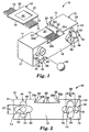
- FIG 1 illustrates an optical cable connector alignment assembly 10 according to one embodiment of the present invention.
- Alignment assembly 10 has a fiber alignment block 12 having a front edge 13, a rear edge 15, an optical fiber receiving surface 14 which engages an optical cable 16, a connector engagement surface 18 which abuts a connector engagement surface on another like connector alignment assembly, a rear face 19 (illustrated in Figure 3a), a first side surface 21 and a second side surface 23 (not seen).
- Cable 16 is comprised of one or more individual optical fibers 17, and in the preferred embodiment the individual optical fibers are positioned adjacent one another in a substantially planar orientation to form a ribbon cable.
- Fiber receiving surface 14 contains a channel 20 formed out of fiber alignment block 12.
- the channel contains first and second channel retaining lips 22, 24 respectively, and a channel floor 26.
- Retaining lips 22, 24 are angled outward from front edge 13 to rear edge 15 to form a trapezoidal shaped channel. Specifically, as retaining lip 24 extends from front edge 13 to rear edge 15, it angles towards first side surface 21. As retaining lip 22 extends from front edge 13 to rear edge 15, it angles toward side surface 23. Also, retaining lips 22, 24 are slanted from top to bottom to form a locking mechanism.
- retaining lips 22, 24 are formed from upper lip edges 22a, 24a and lower lip edges 22b, 24b, respectively.
- Retaining lips 22, 24 slant in at approximately a 30 degree angle such that lower lip edges 22b, 24b are closer to side edges 23, 21, respectively than are upper lip edges 22a, 24a. It should be noted that greater or lesser angles of slant could be used without departing from the scope of the invention.
- One or more alignment grooves 28 are formed in channel floor 26 to retain individual fibers 17 from fiber optic cable 16.
- Alignment grooves 28 of the preferred embodiment are illustrated as being V shaped gooves, but grooves of other cross sectional shapes, such as rectangular, U shaped or semi-circular shaped grooves could also be used without departing from the scope of the invention.
- Also formed in channel floor 26 is a cable jacket receiving channel 30.
- fiber optic cable 16 will be partially stripped to expose individual fibers 17 for placement into alignment grooves 28.
- the cable jacket and optionally any fiber coating surroundi individual fibers 17 will be stripped back a distance at least equal to the length of alignment grooves 28.
- individual fibers 17 may maintain a substantially planar path throughout the entire width of fiber alignment block 12.
- Connector engagement surface 18 and fiber receiving surface 14 in the preferred embodiment are planar surfaces that lie perpendicular to each other. It is also possible, and in some cases beneficial, to have the plane of connector engagement surface 18 a few degrees (preferably 6°-9°) from being perpendicular with fiber receiving surface 14, in order to reduce back reflection of light within the fibers.
- the fiber receiving surface could be either 6°-9° up or down from horizontal without departing from the spirit or scope of the invention. In other words, the angle between fiber receiving surface 14 and connector engagement surface may be in the range of 81°-99°.
- the optical fibers of the present invention may be single or multimode, glass or plastic fibers.
- Multimode glass fibers typically have a core diameter ranging from 50-100 micrometers.
- Single mode fibers have smaller core diameters. Because the multimode fibers have larger core diameters, they offer relaxed alignment tolerances compared to single mode fibers.
- a dove tail retaining member 32 having a front edge 34, a rear edge 36 and side members 38, 40, is provided to secure cable 16 in channel 20, and in particular each of individual fibers 17 in alignment grooves 28.
- An assembly detent 42 is provided on retaining member 32 to assist in installing the retaining member.
- dove tail member 32 is trapezoidal in shape with front edge 34 being shorter than rear edge 36.
- Side members 38 and 40 are substantially the same size.
- Dove tail member 32 substantially conforms to the size and shape of channel 20 and is sized to engagingly slide under channel retaining lips 22 and 24.
- Retaining member 32 has a width at front edge 34 greater than the distance between upper lip edges 22a, 24a and lesser than the distance between lower lip edges 22b, 24b at front edge 13, and has a width at rear edge 36 greater than the distance between upper lip edges 22a, 24a and lesser than the distance between lower lip edges 22b, 24b at rear edge 15.
- Retaining member 32 has a height less than the vertical distance from channel floor 26 to upper lip edges 22a, 24a. The height of retaining member 32 is approximately 2 mm, but greater or lesser heights can be used without departing from the scope of the invention.
- Retaining member 32 is sized such that front edge 34 is wider than channel 20 is at front edge 13, to ensures that when retaining member 32 is installed in channel 20, front edge 34 does not extend past front edge 13 and prohibit tight engagement with opposing connectors.
- Fiber alignment block 12 and retaining member 32 are molded out of ceramic in the preferred embodiment. It would also be possible to make fiber alignment block 12 out of plastic, glass, metal, or any other known connecting block material. By using a moldable material in the preferred embodiment, fiber alignment block 12 may be quickly and easily manufactured as a one piece unit For example, instead of having to carve out channel 20, and alignment grooves 28, in the preferred embodiment they can simply be created by the molding process.
- Connector engagement surface 18 contains a first and a second opening 44, 46 respectively.
- Castellated projections 48, 49 are provided and project from fiber alignment block 12 substantially parallel to each other and optionally substantially perpendicular to connector engagement surface 18. Projections 48, 49 are positioned adjacent openings 44, 46, respectively, and are integrally molded as part of fiber alignment block 12. In the preferred embodiment, castellated projections 48, 49 extend from engagement surface 18 approximately 1/2 the diameter of an alignment ball 62, which will be described in greater detail below.
- projections 48, 49 have rounded inner 50, 51 and outer 52, 53 surfaces respectively. Rounded inner surfaces 50, 51 are adapted to receive the alignment ball, while outer surface 52, 53 are adapted to clearance fit into openings 44, 46 as will be described in detail below.
- Openings 44, 46 can be seen in greater detail in Figure 2. As can be seen, openings 44, 46 are substantially similar in shape, but opening 46 is rotated 90 degrees from opening 44. The purpose of this will be readily apparent after reading the description below. Opening 44 comprises a main cylindrical receiving cavity 54 and a pair of clearance cavities 56. Opening 46 comprises a main cylindrical receiving cavity 58 and a pair of clearance cavities 60. Main cylindrical cavities 54, 58 have diameters d 1 , d 2 , respectively, indicated by arrows 57, 59, respectively. Diameters d 1 , d 2 correspond to the distance between castellated projections 48, 49, respectively.
- diameter d 2 of cylindrical cavity 58 is slightly larger than diameter d 1 of cylindrical cavity 54, and accordingly the distance between projections 49 is slightly greater than the distance between projections 48.
- the difference in diameters d 1 , d 2 is on the order of a few microns. The precise dimensions will depend upon the type of fiber and connector materials selected.
- clearance cavities 56 and castellated projections 48 substantially surround main cylindrical cavity 54.
- castellated projections 49 and clearance cavities 60 substantially surround main cylindrical cavity 58.
- Clearance cavities 56, 60 are shaped substantially similar to castellated projections 48, 49 respectively, and are deep enough to completely receive the projections. It is important that clearance cavities 56, 60 be at least as deep as the castellated projections 48, 49 so that when two connectors are joined, their engagement surfaces 18 can contact each other, thus allowing the ends of the optical fibers carried by each connector to be in dose proximity.
- Precision alignment ball 62 is provided for insertion into opening 44 between castellated projections 48. Precision alignment ball 62 is provided to precisely align fibers 17 in alignment grooves 28 for alignment with fibers in another like connector, as will be described below.
- Ball 62 is a highly precise steel ball bearing but could also be formed from other materials having the precision of a ball bearing such as tungsten carbide, ceramic, other metals, or plastics, such as liquid ciystal polymers, without departing from the scope of the invention.
- ball 62 has a diameter of approximately 2mm and a diameter tolerance of approximately ⁇ 0.5 microns. It is important to note that tolerances will vary depending upon the material used for the alignment ball. While the tolerance ranges are important to the proper operation of the present invention, it will be recognized that greater or lesser diameters may be used, without departing from the scope of the invention.
- d 1 of main cylindrical cavity 54, and therefor the distance between projections 48 is slightly smaller than d 2 of cavity 58. This is to tightly retain ball 62 in cavity 54.
- Castellated projections 49 are designed such that the distance between them (d 2 ) allows them to releasably slide about ball 62. If ball 62 was inserted into opening 46, it would not be tightly retained and could fall out.
- the tolerances for the distances between projections 48, 49 once again depend upon the material used. In the preferred embodiment, ceramic is used for the fiber alignment block, including the projections.
- the tolerance for the distance between projections 48 (which form an interference fit with the alignment ball) is approximately ⁇ 2-3 microns, and the tolerance for the distance between projections 49 (which form a clearance fit with the alignment ball) is approximately ⁇ 0-2 microns. If plastic is used for the projections, the tolerance for the distance between projections 48 is approximately ⁇ 50 microns and for projections 49 is approximately ⁇ 50 microns.
- ball 62 need not be at any specific depth or position in cavity 54, between projections 48. Ball 62 may be retained between projections 48 entirely outside of cavity 54, it may be half inside of cavity 54 and half outside, or it may be entirely inside of the cavity, or anywhere in between, without altering the alignment capabilities of the present invention. It should also be noted that ball 62 could be bonded between projections 48, if desired. Furthermore, it should be noted that it would be posible to have cylindrical cavities 54, 58 the same size, such that both cavities slidingly receive alignment ball 62. While such an embodiment would not prevent ball 62 from falling out of a cavity when connectors are not inounted together, it would give additional freedom in deciding which cavity to insert the ball into.
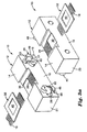
- FIGs 3a and 3b illustrate two connector alignment assemblies made according to the present invention being precisely fitted together.
- Connector alignment assemblies 10 are illustrated having fiber optic ribbon cables 16 retained in alignment grooves 28 by retaining member 32.
- balls 62 have been inserted into receiving cavities 54 of both connector alignment assemblies 10.
- Castellated projections 48 provide a tight fit to retain ball 62 in cavity 54.
- castellated projections 48 fit into clearance cavities 60 and projections 49 fit into clearance cavities 56. Rounded inner surfaces 51 of projections 49 slidingly engage ball 62 as they are inserted into clearance cavities 56.
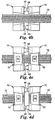
- the present invention also provides a method of automating the assembly of connector alignment assemblies 10 with a ribbon cable.
- This method is illustrated schematically in Figures 4a-d.
- a pair of connector alignment assemblies 10 are provided and are positioned in a face to face arrangement.
- a spacing member 71 is provided to space connector alignment assemblies 10 an appropriate distance apart
- Spacing member 71 of the piesent invention is a disposable spacer that spaces the alignment assemblies approximately 0.038 cm (0.015 inch) apart, but greater or lesser distances may be chosen without departing from the scope of the invention.
- Spacer 71 is preferably made of plastic, but any other suitable spacing material may also be used.
- Connector alignment assemblies 10 may also be secured in place by some sort of clamping mechanism without departing from the scope of the invention.
- a length of fiber optic ribbon cable 72 is provided from a continuous roll or similar continuous supply.
- the ribbon cable is positioned over connector alignment assemblies 10 such that individual fibers are positioned in each of alignment grooves 28.
- a retaining member 32 is then installed on both alignment assemblies 10 to tightly retain the ribbon cable on the connector alignment assemblies.
- ribbon cable 72 is then sawed or cleaved at the location of spacer 71. Finally, any necessary finishing or polishing of the fiber ends is done.
- the above method is also equally applicable to assembling a single connector to the end of a length of ribbon cable.
- the connector alignment assemblies of the present invention are also very well suited for easy field connectorization.
- This type of manual, field connectorization process is illustrated in Figures 5a-c.
- a technician first locates a desired location for connector 10 along a length of ribbon cable 75. The cable is then cut at that point The insulation coating about the fibers is then stripped to expose individual fibers 76. The individual fibers are then placed directly above alignment grooves 28 of the alignment assembly.
- retaining member 32 is slid into channel 20 of the alignment assembly to tightly retain fibers 76 in alignment grooves 28. The portion of the fibers extending beyond connector engagement surface 18 is then cut off, and any necessary finishing or polishing is then performed.
Landscapes
- Physics & Mathematics (AREA)
- General Physics & Mathematics (AREA)
- Optics & Photonics (AREA)
- Engineering & Computer Science (AREA)
- Microelectronics & Electronic Packaging (AREA)
- Mechanical Coupling Of Light Guides (AREA)
Claims (12)
- Un ensemble d'alignement (10) de connecteur de câble à fibres optiques comprenant:caractérisé parun bloc d'alignement (12) de fibres qui inclut une surface réceptrice (14) de fibres pour recevoir au moins une fibre optique d'un câble (16) à fibres optiques et une surface de contact (18) de connecteur, etune première et une deuxième ouvertures (44, 46) formées dans la surface de contact (18) de connecteur,une bille d'alignement (62) retenue dans la première ouverture (44),une première paire de saillies (48) adjacente à la première ouverture (44) et une deuxième paire de saillies (49) adjacente à la deuxième ouverture (46), les saillies (48, 49) faisant saillie de la surface de contact (18) de connecteur, etdans lequel la première ouverture (44) est dimensionnée pour recevoir la deuxième paire de saillies (49) et la deuxième ouverture (46) est dimensionnée tant pour recevoir la première paire de saillie (48) quepour recevoir à coulissement une bille d'alignement (62) retenue dans un ensemble correspondant d'alignement (10) de connecteur auquel le connecteur de câble de fibres optiques sera accouplé.
- L'ensemble d'alignement de connecteur selon la revendication 1, dans lequel la bille d'alignement (62) est retenue entre les saillies (48) de la première paire.
- L'ensemble d'alignement de connecteur selon la revendication 1 ou 2, dans lequel la bille d'alignement (62) peut être mise en contact coulissant avec la deuxième paire de saillies (49).
- L'ensemble d'alignement de connecteur selon la revendication 1 ou 2 dans lequel la bille d'alignement (62) est attachée de façon fixe dans la première ouverture (44).
- L'ensemble d'alignement de connecteur selon la revendication 4, dans lequel la bille d'alignement (62) est attachée dans la première ouverture (44).
- L'ensemble d'alignement de connecteur selon l'une quelconque des revendications 1 à 5 dans lequel la surface réceptrice (14) de fibres comprend au moins une rainure d'alignement (28) pour retenir au moins une fibre du câble de fibres optiques.
- L'ensemble d'alignement de connecteur selon l'une quelconque des revendications 1 à 6 dans lequel la surface de contact (18) de connecteur forme avec la surface réceptrice (14) de fibres un angle compris dans une plage de 81 à 99°.
- L'ensemble d'alignement de connecteur selon l'une quelconque des revendications 1 à 7 dans lequel la première et la deuxième ouvertures (44, 46) se connectent à un premier et un deuxième alésages, respectivement, et dans lequel le premier et le deuxième alésages se prolongent sur toute la largeur du bloc d'alignement (12) de fibres.
- Un ensemble d'alignement (10) de connecteur de fibres optiques selon l'une quelconque des revendications 1 à 8, qui comprend en outre:un canal (20) formé dans la surface réceptrice (14) de fibres,au moins une rainure d'alignement (28) formée dans le canal (20), etun organe d'attache (32) dimensionné pour s'ajuster dans le canal (20) pour attacher la fibre optique unique au moins dans la rainure d'alignement (28) unique au moins.
- L'ensemble d'alignement de connecteur selon la revendication 9 dans lequel le canal (20) comporte une surface (26) de canal et une première et une deuxième lèvres (22, 24) de canal et dans lequel les lèvres (22, 24) de canal comprennent des bords supérieurs et inférieurs (22a, 24a, 22b, 24b) de lèvres, dans lequel les bords supérieurs (22a, 24a) des lèvres sont à une première distance l'un de l'autre et les bords inférieurs (22b, 24b) des lèvres sont à une deuxième distance l'un de l'autre et les bords supérieurs (22a, 24a) de lèvres sont à une troisième distance de la surface (26) du canal, et dans lequel les lèvres (22, 24) du canal sont inclinées vers l'intérieur à partir des bords supérieurs (22a, 24a) de lèvres vers les bords inférieurs (22b, 24b) de lèvres, d'une façon telle que la première distance entre les bords supérieurs (22a, 24a) de lèvres est inférieure à la deuxième distance entre les bords inférieurs (22b, 24b) de lèvres.
- L'ensemble d'alignement de connecteur selon la revendication 10 dans lequel l' épaisseur de l'organe d'attache (32) est inférieure à la troisième distance entre les bords supérieurs (22a, 24a) des lèvres et la surface (26) du canal.
- L'ensemble d'alignement de connecteur selon la revendication 10 ou 11 dans lequel l'organe d'attache (32) est retenu dans le canal (20) par les première et deuxième lèvres (22, 24) de canal lorsque l'organe d'attache (32) est inséré dans le canal (20).
Priority Applications (2)
| Application Number | Priority Date | Filing Date | Title |
|---|---|---|---|
| EP00111353A EP1028336A3 (fr) | 1996-03-12 | 1996-10-07 | Ensemble d'alignement pour connecteur de cables optiques à une ou plusieurs fibres |
| EP00111351A EP1028335A3 (fr) | 1996-03-12 | 1996-10-07 | Ensemble d'alignement pour connecteur de cables optiques à une ou plusieurs fibres |
Applications Claiming Priority (3)
| Application Number | Priority Date | Filing Date | Title |
|---|---|---|---|
| US08/614,412 US5778123A (en) | 1996-03-12 | 1996-03-12 | Alignment assembly for multifiber or single fiber optical cable connector |
| US614412 | 1996-03-12 | ||
| PCT/US1996/016052 WO1997034179A1 (fr) | 1996-03-12 | 1996-10-07 | Ensemble d'alignement pour connecteur de cables optiques a une ou plusieurs fibres |
Related Child Applications (2)
| Application Number | Title | Priority Date | Filing Date |
|---|---|---|---|
| EP00111351A Division EP1028335A3 (fr) | 1996-03-12 | 1996-10-07 | Ensemble d'alignement pour connecteur de cables optiques à une ou plusieurs fibres |
| EP00111353A Division EP1028336A3 (fr) | 1996-03-12 | 1996-10-07 | Ensemble d'alignement pour connecteur de cables optiques à une ou plusieurs fibres |
Publications (2)
| Publication Number | Publication Date |
|---|---|
| EP0886797A1 EP0886797A1 (fr) | 1998-12-30 |
| EP0886797B1 true EP0886797B1 (fr) | 2002-01-02 |
Family
ID=24461155
Family Applications (3)
| Application Number | Title | Priority Date | Filing Date |
|---|---|---|---|
| EP00111353A Withdrawn EP1028336A3 (fr) | 1996-03-12 | 1996-10-07 | Ensemble d'alignement pour connecteur de cables optiques à une ou plusieurs fibres |
| EP00111351A Withdrawn EP1028335A3 (fr) | 1996-03-12 | 1996-10-07 | Ensemble d'alignement pour connecteur de cables optiques à une ou plusieurs fibres |
| EP96934091A Expired - Lifetime EP0886797B1 (fr) | 1996-03-12 | 1996-10-07 | Ensemble d'alignement pour connecteur de cables optiques a une ou plusieurs fibres |
Family Applications Before (2)
| Application Number | Title | Priority Date | Filing Date |
|---|---|---|---|
| EP00111353A Withdrawn EP1028336A3 (fr) | 1996-03-12 | 1996-10-07 | Ensemble d'alignement pour connecteur de cables optiques à une ou plusieurs fibres |
| EP00111351A Withdrawn EP1028335A3 (fr) | 1996-03-12 | 1996-10-07 | Ensemble d'alignement pour connecteur de cables optiques à une ou plusieurs fibres |
Country Status (9)
| Country | Link |
|---|---|
| US (2) | US5778123A (fr) |
| EP (3) | EP1028336A3 (fr) |
| JP (1) | JP2000505208A (fr) |
| KR (1) | KR19990087648A (fr) |
| CN (1) | CN1129016C (fr) |
| DE (1) | DE69618668T2 (fr) |
| HK (1) | HK1019169A1 (fr) |
| TW (1) | TW381186B (fr) |
| WO (1) | WO1997034179A1 (fr) |
Families Citing this family (69)
| Publication number | Priority date | Publication date | Assignee | Title |
|---|---|---|---|---|
| US5778123A (en) * | 1996-03-12 | 1998-07-07 | Minnesota Mining And Manufacturing Company | Alignment assembly for multifiber or single fiber optical cable connector |
| US5940562A (en) * | 1996-03-12 | 1999-08-17 | Minnesota Mining And Manufacturing Company | Stubless optoelectronic device receptacle |
| US6318902B1 (en) | 1996-03-12 | 2001-11-20 | 3M Innovative Properties Company | Optical connector assembly using partial large diameter alignment features |
| US6805493B2 (en) | 1996-03-12 | 2004-10-19 | 3M Innovative Properties Company | Optical connector assembly using partial large diameter alignment features |
| US5920670A (en) * | 1996-06-07 | 1999-07-06 | 3M Innovative Properties Company | Multiple alignment connector ferrule |
| CA2262351A1 (fr) * | 1998-02-24 | 1999-08-24 | Jds Fitel Inc. | Connecteur optique accordable de fibres multiples |
| JPH11344640A (ja) * | 1998-03-31 | 1999-12-14 | Ngk Insulators Ltd | ガラス基板及びその2段階成形方法 |
| JPH11281823A (ja) * | 1998-03-31 | 1999-10-15 | Oki Electric Ind Co Ltd | 光ファイバの整列方法及び光ファイバアレイ装置 |
| US6478474B1 (en) | 1998-07-02 | 2002-11-12 | Tyco Electronics Logistics Ag | Ferrule for an optical plug-in connection |
| FR2786881B1 (fr) * | 1998-12-03 | 2002-08-16 | Socapex Amphenol | Connecteur optique hermaphrodite |
| US6332052B1 (en) * | 2000-02-28 | 2001-12-18 | Corning Cable Systems Llc | Optical fiber ribbon cables with controlled bending behavior |
| US6832016B2 (en) * | 2000-04-13 | 2004-12-14 | Shipley Company, L.L.C. | Fiber array switch having micromachined front face with roller balls |
| US6798933B2 (en) * | 2000-04-14 | 2004-09-28 | Shipley Company, L.L.C. | Fiber optic array switch |
| US6842552B1 (en) | 2000-04-13 | 2005-01-11 | Shipley Company, L.L.C. | Optical waveguide switch |
| US6826324B2 (en) * | 2000-04-13 | 2004-11-30 | Shipley Company, L.L.C. | Optical waveguide switch |
| US6633691B2 (en) * | 2000-05-02 | 2003-10-14 | Shipley Company, L.L.C. | Optical waveguide switch having stepped waveguide holding member |
| US6748131B2 (en) * | 2000-05-19 | 2004-06-08 | Shipley Company, L.L.C. | Optical waveguide devices and methods of fabricating the same |
| US6434315B1 (en) * | 2000-06-23 | 2002-08-13 | Molex Incorporated | Fiber optic connector |
| US6434316B1 (en) * | 2000-06-23 | 2002-08-13 | Molex Incorporated | Fiber optic connector |
| US6870981B2 (en) | 2000-08-24 | 2005-03-22 | Shipley Company, L.L.C. | Optical switch and method for making |
| US6853764B2 (en) * | 2000-08-28 | 2005-02-08 | Shipley Company, L.L.C. | Optical switch assembly and method for making |
| US6798968B2 (en) * | 2000-09-21 | 2004-09-28 | Shipley Company, L.L.C. | Fiber array with support post |
| US6526205B1 (en) * | 2000-10-13 | 2003-02-25 | Agilent Technologies, Inc. | Method and apparatus for the passive alignment of optical components |
| US6520686B1 (en) | 2000-11-09 | 2003-02-18 | Teradyne, Inc. | Methods and apparatus for forming a fiber optic connection |
| US6799897B2 (en) | 2000-11-16 | 2004-10-05 | Shipley Company, L.L.C. | Optical connector system |
| US6810162B2 (en) * | 2000-12-20 | 2004-10-26 | Shipley Company, L.L.C. | Optical switch assembly with flex plate and method for making |
| US6527457B2 (en) | 2001-02-01 | 2003-03-04 | International Business Machines Corporation | Optical fiber guide module and a method for making the same |
| JP2002328251A (ja) * | 2001-02-28 | 2002-11-15 | Asahi Glass Co Ltd | 樹脂製光ファイバの接合法 |
| US6623177B1 (en) | 2001-07-09 | 2003-09-23 | Emc Corporation | Systems and methods for providing fiber optic communications between circuit boards |
| US20030086661A1 (en) * | 2001-11-02 | 2003-05-08 | Boudreau Robert A. | Silicon waferboard |
| AU2002357700A1 (en) * | 2001-11-08 | 2003-05-19 | Shipley Company, Llc | Fiber optic termination |
| US6839935B2 (en) * | 2002-05-29 | 2005-01-11 | Teradyne, Inc. | Methods and apparatus for cleaning optical connectors |
| US6957920B2 (en) | 2002-06-24 | 2005-10-25 | Corning Cable Systems Llc | Ferrule assembly having highly protruding optical fibers and an associated fabrication method |
| US6762941B2 (en) | 2002-07-15 | 2004-07-13 | Teradyne, Inc. | Techniques for connecting a set of connecting elements using an improved latching apparatus |
| US6832858B2 (en) * | 2002-09-13 | 2004-12-21 | Teradyne, Inc. | Techniques for forming fiber optic connections in a modularized manner |
| US7042562B2 (en) * | 2002-12-26 | 2006-05-09 | Amphenol Corp. | Systems and methods for inspecting an optical interface |
| JP2005352453A (ja) * | 2004-05-12 | 2005-12-22 | Nec Corp | 光ファイバ部品及び光導波路モジュール並びにこれらの製造方法 |
| KR101119780B1 (ko) * | 2005-06-30 | 2012-03-23 | 엘지디스플레이 주식회사 | 플라즈마 화학증착장치 |
| WO2007009491A1 (fr) * | 2005-07-15 | 2007-01-25 | Diamond Sa | Connexion enfichable multifibre optique |
| US7572063B2 (en) * | 2005-09-12 | 2009-08-11 | Stratos International, Inc. | Opto-electric connector |
| US7515782B2 (en) * | 2006-03-17 | 2009-04-07 | Zhang Boying B | Two-channel, dual-mode, fiber optic rotary joint |
| JP4901654B2 (ja) * | 2007-09-03 | 2012-03-21 | 株式会社フジクラ | 光コネクタ |
| US20090196563A1 (en) * | 2008-02-01 | 2009-08-06 | Mullsteff David M | Multi-Fiber Optical Patch Cord Breakout Assembly |
| KR101394844B1 (ko) | 2008-05-09 | 2014-05-14 | 휴렛-팩커드 디벨롭먼트 컴퍼니, 엘.피. | 근접 자유 공간 광학적 상호접속부 |
| US20100067852A1 (en) * | 2008-09-18 | 2010-03-18 | International Business Machines Corporation | Method for assembling a furrule for an optical wave guide connector, ferrule, wave guide ribbon and tool for assembling the ferrule |
| CN102405429A (zh) * | 2009-03-17 | 2012-04-04 | Adc电信公司 | 在光纤电缆上直接模塑套圈的方法 |
| US8408816B2 (en) | 2010-03-18 | 2013-04-02 | Fujikura Ltd. | Optical connector |
| US8529138B2 (en) * | 2010-07-15 | 2013-09-10 | Tyco Electronics Corporation | Ferrule for optical transports |
| EP2598926A1 (fr) * | 2010-07-30 | 2013-06-05 | Corning Cable Systems LLC | Viroles à géométrie d'accouplement complémentaire et connecteurs de fibres optiques associés |
| US9529159B2 (en) * | 2010-07-30 | 2016-12-27 | Corning Optical Communications LLC | Ferrules with complementary mating geometry and related fiber optic connectors |
| US10401572B2 (en) * | 2010-07-30 | 2019-09-03 | Corning Optical Communications, Llc | Fiber optic connectors including ferrules with complementary mating geometry and related fiber optic connectors |
| US8585300B2 (en) * | 2011-02-09 | 2013-11-19 | Tyco Electronics Nederland Bv | Ferrule with alignment pin channels |
| TWM449965U (zh) * | 2011-06-14 | 2013-04-01 | Molex Inc | 具有一體扣合機構的套管組件 |
| US10215926B2 (en) | 2011-12-14 | 2019-02-26 | Commscope Technologies Llc | Multi-fiber fiber optic connection system with flexible, insertable pins |
| TWI561877B (en) * | 2012-03-23 | 2016-12-11 | Hon Hai Prec Ind Co Ltd | Photoelectric transmitting module and optical fiber connector thereof |
| CA2869742A1 (fr) * | 2012-04-11 | 2014-01-16 | Nanoprecision Products, Inc. | Assemblage hermetique d'alignement de fibres optiques |
| US9897764B2 (en) | 2012-09-28 | 2018-02-20 | Commscope Technologies Llc | Molded ferrules for optical fibers |
| JP2014106409A (ja) * | 2012-11-28 | 2014-06-09 | International Business Maschines Corporation | 複数積層の光導波路コネクタ |
| CN104678504B (zh) * | 2013-11-30 | 2018-07-27 | 内蒙古炎林通讯技术有限公司 | 光纤连接器 |
| JP6459334B2 (ja) * | 2014-09-18 | 2019-01-30 | 住友電気工業株式会社 | フェルール及び光接続構造 |
| WO2016087449A1 (fr) | 2014-12-01 | 2016-06-09 | Commscope Asia Holdings B.V. | Connecteur optique multifibre à ferrule alignée de manière pivotante |
| WO2016205201A1 (fr) | 2015-06-19 | 2016-12-22 | Commscope Technologies Llc | Ferrule de connecteur de fibre optique à mécanisme d'alignement amélioré |
| JP6971240B2 (ja) * | 2015-10-12 | 2021-11-24 | スリーエム イノベイティブ プロパティズ カンパニー | 光フェルール |
| WO2018186037A1 (fr) * | 2017-04-04 | 2018-10-11 | Tdk株式会社 | Élément de fibre optique et support de fibre optique |
| CN107577014B (zh) * | 2017-09-11 | 2019-06-28 | 武汉福地科技有限公司 | 一种具有收发一体功能的光纤阵列连接设备 |
| CN113710738A (zh) | 2019-03-20 | 2021-11-26 | 提克纳有限责任公司 | 用于相机模块的致动器组件 |
| US11086200B2 (en) | 2019-03-20 | 2021-08-10 | Ticona Llc | Polymer composition for use in a camera module |
| WO2020235041A1 (fr) * | 2019-05-22 | 2020-11-26 | 日本電信電話株式会社 | Structure de connexion de guide d'ondes, puce de guide d'ondes, connecteur, procédé de fabrication de composant de connexion de guide d'ondes, et procédé de connexion de gude d'ondes |
| US10942316B1 (en) * | 2019-10-31 | 2021-03-09 | Alliance Fiber Optic Products, Inc. | FAU connectors and assemblies employing pin-to-pin alignment |
Citations (2)
| Publication number | Priority date | Publication date | Assignee | Title |
|---|---|---|---|---|
| DE3409641A1 (de) * | 1984-03-16 | 1985-09-19 | Standard Elektrik Lorenz Ag, 7000 Stuttgart | Steckverbindung fuer lichtwellenleiter |
| US5257334A (en) * | 1991-09-24 | 1993-10-26 | Seikoh Giken Co., Ltd. | Ribbon type optical fiber connector |
Family Cites Families (27)
| Publication number | Priority date | Publication date | Assignee | Title |
|---|---|---|---|---|
| US3871935A (en) * | 1974-03-14 | 1975-03-18 | Bell Telephone Labor Inc | Method of encapsulating and terminating the fibers of an optical fiber ribbon |
| US4037902A (en) * | 1976-03-16 | 1977-07-26 | Tesco Engineering Company | Hermaphroditic multiple connector plug |
| US4094580A (en) * | 1976-12-27 | 1978-06-13 | Bell Telephone Laboratories, Incorporated | Hermaphrodite optical fiber connector |
| US4116532A (en) * | 1977-01-05 | 1978-09-26 | Bell Telephone Laboratories, Incorporated | Fiber positioning and connection method and apparatus |
| US4087155A (en) * | 1977-03-23 | 1978-05-02 | International Telephone & Telegraph Corporation | Single optical fiber connector utilizing spherical alignment elements |
| GB1600272A (en) * | 1977-05-02 | 1981-10-14 | Plessey Co Ltd | Optical fibre connectors |
| US4279466A (en) * | 1978-02-21 | 1981-07-21 | Bunker Ramo Corporation | Hermaphroditic fiber optic connector |
| US4184742A (en) * | 1978-10-26 | 1980-01-22 | International Telephone And Telegraph Corporation | Hermaphroditic fiber optic connector |
| US4712861A (en) * | 1985-02-07 | 1987-12-15 | Northern Telecom Limited | Two-channel hermaphroditic fiber connector |
| US4737118A (en) * | 1985-12-20 | 1988-04-12 | Amp Incorporated | Hermaphroditic flat cable connector |
| US4953944A (en) * | 1988-10-12 | 1990-09-04 | Hughes Aircraft Company | Multi-channel hermaphroditic lens type fiber optic connector |
| US5183409A (en) * | 1991-04-15 | 1993-02-02 | Eric Clever | Hermaphroditic multiple contact connector |
| AU635172B2 (en) * | 1991-05-13 | 1993-03-11 | Nippon Telegraph & Telephone Corporation | Multifiber optical connector plug with low reflection and low insertion loss |
| US5121457A (en) * | 1991-05-21 | 1992-06-09 | Gte Laboratories Incorporated | Method for coupling laser array to optical fiber array |
| US5123073A (en) * | 1991-05-31 | 1992-06-16 | At&T Bell Laboratories | Precision optical fiber connector |
| AU649162B2 (en) * | 1991-08-17 | 1994-05-12 | Nippon Telegraph & Telephone Corporation | Optical connector |
| US5151964A (en) * | 1991-09-06 | 1992-09-29 | Minnesota Mining And Manufacturing Company | Wedge-actuated multiple optical fiber splice |
| US5315678A (en) * | 1992-03-30 | 1994-05-24 | Nippon Telegraph & Telephone Corporation | Optical fiber connector |
| US5257332A (en) * | 1992-09-04 | 1993-10-26 | At&T Bell Laboratories | Optical fiber expanded beam coupler |
| CA2114689C (fr) * | 1993-02-02 | 2000-03-28 | Makoto Honjo | Connecteur optique et l'adhesif correspondant |
| JPH06337328A (ja) * | 1993-03-29 | 1994-12-06 | Sumitomo Electric Ind Ltd | 光コネクタ |
| JPH0720340A (ja) * | 1993-06-28 | 1995-01-24 | Nippon Telegr & Teleph Corp <Ntt> | 光ファイバブロックアレイ及びその製造方法 |
| US5333225A (en) * | 1993-08-03 | 1994-07-26 | International Business Machines Corporation | Substrate-embedded pluggable receptacles for connecting clustered optical cables to a module |
| US5430819A (en) * | 1993-12-21 | 1995-07-04 | At&T Corp. | Multiple optical fiber connector and method of making same |
| JP3256922B2 (ja) * | 1994-10-13 | 2002-02-18 | 古河電気工業株式会社 | 光コネクタ |
| US5778123A (en) * | 1996-03-12 | 1998-07-07 | Minnesota Mining And Manufacturing Company | Alignment assembly for multifiber or single fiber optical cable connector |
| US5727097A (en) * | 1996-06-07 | 1998-03-10 | Minnesota Mining And Manufacturing Company | Pull-proof fiber optic array connector |
-
1996
- 1996-03-12 US US08/614,412 patent/US5778123A/en not_active Expired - Fee Related
- 1996-10-07 EP EP00111353A patent/EP1028336A3/fr not_active Withdrawn
- 1996-10-07 KR KR1019980707105A patent/KR19990087648A/ko not_active Application Discontinuation
- 1996-10-07 JP JP9511495A patent/JP2000505208A/ja not_active Withdrawn
- 1996-10-07 CN CN96180202A patent/CN1129016C/zh not_active Expired - Fee Related
- 1996-10-07 DE DE69618668T patent/DE69618668T2/de not_active Expired - Fee Related
- 1996-10-07 EP EP00111351A patent/EP1028335A3/fr not_active Withdrawn
- 1996-10-07 EP EP96934091A patent/EP0886797B1/fr not_active Expired - Lifetime
- 1996-10-07 WO PCT/US1996/016052 patent/WO1997034179A1/fr not_active Application Discontinuation
-
1997
- 1997-02-14 TW TW086101690A patent/TW381186B/zh active
- 1997-10-20 US US08/953,950 patent/US5845028A/en not_active Expired - Fee Related
-
1999
- 1999-10-04 HK HK99104305A patent/HK1019169A1/xx not_active IP Right Cessation
Patent Citations (2)
| Publication number | Priority date | Publication date | Assignee | Title |
|---|---|---|---|---|
| DE3409641A1 (de) * | 1984-03-16 | 1985-09-19 | Standard Elektrik Lorenz Ag, 7000 Stuttgart | Steckverbindung fuer lichtwellenleiter |
| US5257334A (en) * | 1991-09-24 | 1993-10-26 | Seikoh Giken Co., Ltd. | Ribbon type optical fiber connector |
Also Published As
| Publication number | Publication date |
|---|---|
| US5778123A (en) | 1998-07-07 |
| TW381186B (en) | 2000-02-01 |
| CN1129016C (zh) | 2003-11-26 |
| JP2000505208A (ja) | 2000-04-25 |
| HK1019169A1 (en) | 2000-01-14 |
| EP1028336A3 (fr) | 2000-09-06 |
| KR19990087648A (ko) | 1999-12-27 |
| CN1214122A (zh) | 1999-04-14 |
| WO1997034179A1 (fr) | 1997-09-18 |
| EP1028335A3 (fr) | 2000-09-06 |
| DE69618668D1 (de) | 2002-02-28 |
| DE69618668T2 (de) | 2002-08-14 |
| US5845028A (en) | 1998-12-01 |
| EP0886797A1 (fr) | 1998-12-30 |
| EP1028336A2 (fr) | 2000-08-16 |
| EP1028335A2 (fr) | 2000-08-16 |
Similar Documents
| Publication | Publication Date | Title |
|---|---|---|
| EP0886797B1 (fr) | Ensemble d'alignement pour connecteur de cables optiques a une ou plusieurs fibres | |
| EP0988570B1 (fr) | Ferrule de connecteur a alignement multiple | |
| US6550979B1 (en) | Floating connector subassembly and connector including same | |
| US9279942B2 (en) | Ferrule for optical fiber connector having a compliant structure for clamping alignment pins | |
| EP0002565B1 (fr) | Connecteur pour fibres optiques | |
| CA1121629A (fr) | Connecteurs de fibres optiques simples | |
| US4385801A (en) | Fibre-to-fibre connector including a component for joining it to an optical cable | |
| CN103597389A (zh) | 具有开放的光纤夹紧槽的光纤连接器套圈 | |
| US5016972A (en) | Detachable multiple splicing connector for light waveguides | |
| US6722791B2 (en) | Multi-fiber ferrule | |
| EP0015291B1 (fr) | Piece de raccordement pour fibres optiques | |
| US6616462B2 (en) | Convertible multi-diameter sleeve for optical fiber connectors | |
| JP2002531869A (ja) | 大きな径のアライメントピンを用いた光コネクタ | |
| US20030091297A1 (en) | Fiber optic connector and method of making the same | |
| WO2020081439A1 (fr) | Ferrules comprenant des éléments de clavetage et jonctions à fibres optiques comprenant celles-ci | |
| US20240036267A1 (en) | Method for making a low-loss fiber optic connector | |
| EP1010999A2 (fr) | Adapteurs à rainures en "V" pour l'interconnexion de guides d'ondes optiques, et procédé de leur fabrication | |
| WO2022137620A1 (fr) | Ensemble optique et procédé de fabrication d'ensemble optique | |
| EP3629069A1 (fr) | Connecteur de câble à fibre optique multicanaux | |
| JPH0414727Y2 (fr) |
Legal Events
| Date | Code | Title | Description |
|---|---|---|---|
| PUAI | Public reference made under article 153(3) epc to a published international application that has entered the european phase |
Free format text: ORIGINAL CODE: 0009012 |
|
| 17P | Request for examination filed |
Effective date: 19980822 |
|
| AK | Designated contracting states |
Kind code of ref document: A1 Designated state(s): DE FR GB IT SE |
|
| 17Q | First examination report despatched |
Effective date: 19991222 |
|
| GRAG | Despatch of communication of intention to grant |
Free format text: ORIGINAL CODE: EPIDOS AGRA |
|
| GRAG | Despatch of communication of intention to grant |
Free format text: ORIGINAL CODE: EPIDOS AGRA |
|
| GRAH | Despatch of communication of intention to grant a patent |
Free format text: ORIGINAL CODE: EPIDOS IGRA |
|
| GRAH | Despatch of communication of intention to grant a patent |
Free format text: ORIGINAL CODE: EPIDOS IGRA |
|
| GRAA | (expected) grant |
Free format text: ORIGINAL CODE: 0009210 |
|
| REG | Reference to a national code |
Ref country code: GB Ref legal event code: IF02 |
|
| AK | Designated contracting states |
Kind code of ref document: B1 Designated state(s): DE FR GB IT SE |
|
| REF | Corresponds to: |
Ref document number: 69618668 Country of ref document: DE Date of ref document: 20020228 |
|
| ET | Fr: translation filed | ||
| PGFP | Annual fee paid to national office [announced via postgrant information from national office to epo] |
Ref country code: FR Payment date: 20020918 Year of fee payment: 7 |
|
| PGFP | Annual fee paid to national office [announced via postgrant information from national office to epo] |
Ref country code: SE Payment date: 20020919 Year of fee payment: 7 |
|
| PGFP | Annual fee paid to national office [announced via postgrant information from national office to epo] |
Ref country code: GB Payment date: 20021002 Year of fee payment: 7 |
|
| PGFP | Annual fee paid to national office [announced via postgrant information from national office to epo] |
Ref country code: DE Payment date: 20021031 Year of fee payment: 7 |
|
| PLBE | No opposition filed within time limit |
Free format text: ORIGINAL CODE: 0009261 |
|
| STAA | Information on the status of an ep patent application or granted ep patent |
Free format text: STATUS: NO OPPOSITION FILED WITHIN TIME LIMIT |
|
| 26N | No opposition filed | ||
| PG25 | Lapsed in a contracting state [announced via postgrant information from national office to epo] |
Ref country code: GB Free format text: LAPSE BECAUSE OF NON-PAYMENT OF DUE FEES Effective date: 20031007 |
|
| PG25 | Lapsed in a contracting state [announced via postgrant information from national office to epo] |
Ref country code: SE Free format text: LAPSE BECAUSE OF NON-PAYMENT OF DUE FEES Effective date: 20031008 |
|
| PG25 | Lapsed in a contracting state [announced via postgrant information from national office to epo] |
Ref country code: DE Free format text: LAPSE BECAUSE OF NON-PAYMENT OF DUE FEES Effective date: 20040501 |
|
| GBPC | Gb: european patent ceased through non-payment of renewal fee |
Effective date: 20031007 |
|
| EUG | Se: european patent has lapsed | ||
| PG25 | Lapsed in a contracting state [announced via postgrant information from national office to epo] |
Ref country code: FR Free format text: LAPSE BECAUSE OF NON-PAYMENT OF DUE FEES Effective date: 20040630 |
|
| REG | Reference to a national code |
Ref country code: FR Ref legal event code: ST |
|
| PG25 | Lapsed in a contracting state [announced via postgrant information from national office to epo] |
Ref country code: IT Free format text: LAPSE BECAUSE OF NON-PAYMENT OF DUE FEES;WARNING: LAPSES OF ITALIAN PATENTS WITH EFFECTIVE DATE BEFORE 2007 MAY HAVE OCCURRED AT ANY TIME BEFORE 2007. THE CORRECT EFFECTIVE DATE MAY BE DIFFERENT FROM THE ONE RECORDED. Effective date: 20051007 |