EP0885559B1 - Misch- und Verteilwagen für Futter - Google Patents
Misch- und Verteilwagen für Futter Download PDFInfo
- Publication number
- EP0885559B1 EP0885559B1 EP98111175A EP98111175A EP0885559B1 EP 0885559 B1 EP0885559 B1 EP 0885559B1 EP 98111175 A EP98111175 A EP 98111175A EP 98111175 A EP98111175 A EP 98111175A EP 0885559 B1 EP0885559 B1 EP 0885559B1
- Authority
- EP
- European Patent Office
- Prior art keywords
- mixing
- wagon
- distributing
- floor
- shaft
- Prior art date
- Legal status (The legal status is an assumption and is not a legal conclusion. Google has not performed a legal analysis and makes no representation as to the accuracy of the status listed.)
- Expired - Lifetime
Links
- 239000004033 plastic Substances 0.000 claims description 9
- 239000002184 metal Substances 0.000 claims description 8
- 238000013459 approach Methods 0.000 claims description 4
- 230000007704 transition Effects 0.000 claims description 3
- 239000002023 wood Substances 0.000 claims description 3
- 239000011248 coating agent Substances 0.000 claims 1
- 238000000576 coating method Methods 0.000 claims 1
- 230000008878 coupling Effects 0.000 claims 1
- 238000010168 coupling process Methods 0.000 claims 1
- 238000005859 coupling reaction Methods 0.000 claims 1
- 238000006073 displacement reaction Methods 0.000 claims 1
- 230000001404 mediated effect Effects 0.000 claims 1
- 238000010008 shearing Methods 0.000 claims 1
- 239000000969 carrier Substances 0.000 description 11
- 238000010276 construction Methods 0.000 description 6
- 239000000835 fiber Substances 0.000 description 5
- 230000000694 effects Effects 0.000 description 4
- 238000000034 method Methods 0.000 description 4
- 239000004460 silage Substances 0.000 description 3
- 239000004459 forage Substances 0.000 description 2
- 230000005484 gravity Effects 0.000 description 2
- 239000002689 soil Substances 0.000 description 2
- 239000000853 adhesive Substances 0.000 description 1
- 230000001070 adhesive effect Effects 0.000 description 1
- 230000001174 ascending effect Effects 0.000 description 1
- 238000005452 bending Methods 0.000 description 1
- 238000005253 cladding Methods 0.000 description 1
- 230000002349 favourable effect Effects 0.000 description 1
- 239000002657 fibrous material Substances 0.000 description 1
- 239000004461 grass silage Substances 0.000 description 1
- 238000010422 painting Methods 0.000 description 1
- 238000009304 pastoral farming Methods 0.000 description 1
- 230000001737 promoting effect Effects 0.000 description 1
- 230000003014 reinforcing effect Effects 0.000 description 1
- 239000007787 solid Substances 0.000 description 1
Images


Classifications
-
- A—HUMAN NECESSITIES
- A01—AGRICULTURE; FORESTRY; ANIMAL HUSBANDRY; HUNTING; TRAPPING; FISHING
- A01K—ANIMAL HUSBANDRY; AVICULTURE; APICULTURE; PISCICULTURE; FISHING; REARING OR BREEDING ANIMALS, NOT OTHERWISE PROVIDED FOR; NEW BREEDS OF ANIMALS
- A01K5/00—Feeding devices for stock or game ; Feeding wagons; Feeding stacks
- A01K5/001—Fodder distributors with mixer or shredder
- A01K5/002—Fodder distributors with mixer or shredder with mixing or shredding element rotating on horizontal axis
-
- B—PERFORMING OPERATIONS; TRANSPORTING
- B01—PHYSICAL OR CHEMICAL PROCESSES OR APPARATUS IN GENERAL
- B01F—MIXING, e.g. DISSOLVING, EMULSIFYING OR DISPERSING
- B01F27/00—Mixers with rotary stirring devices in fixed receptacles; Kneaders
- B01F27/60—Mixers with rotary stirring devices in fixed receptacles; Kneaders with stirrers rotating about a horizontal or inclined axis
-
- B—PERFORMING OPERATIONS; TRANSPORTING
- B01—PHYSICAL OR CHEMICAL PROCESSES OR APPARATUS IN GENERAL
- B01F—MIXING, e.g. DISSOLVING, EMULSIFYING OR DISPERSING
- B01F33/00—Other mixers; Mixing plants; Combinations of mixers
- B01F33/50—Movable or transportable mixing devices or plants
- B01F33/502—Vehicle-mounted mixing devices
- B01F33/5023—Vehicle-mounted mixing devices the vehicle being a trailer which is hand moved or coupled to self-propelling vehicles
-
- B—PERFORMING OPERATIONS; TRANSPORTING
- B01—PHYSICAL OR CHEMICAL PROCESSES OR APPARATUS IN GENERAL
- B01F—MIXING, e.g. DISSOLVING, EMULSIFYING OR DISPERSING
- B01F2101/00—Mixing characterised by the nature of the mixed materials or by the application field
- B01F2101/06—Mixing of food ingredients
- B01F2101/18—Mixing animal food ingredients
-
- B—PERFORMING OPERATIONS; TRANSPORTING
- B01—PHYSICAL OR CHEMICAL PROCESSES OR APPARATUS IN GENERAL
- B01F—MIXING, e.g. DISSOLVING, EMULSIFYING OR DISPERSING
- B01F33/00—Other mixers; Mixing plants; Combinations of mixers
- B01F33/50—Movable or transportable mixing devices or plants
- B01F33/502—Vehicle-mounted mixing devices
Definitions
- the present invention relates to a mixing and distribution wagon for feed, according to the preamble of the claim 1.
- a carriage is known from DE 295 11 311 U.
- Such cars have been in practical operation known for a long time. They are primarily used for transportation of feed, for example green or dry feed or Silage, and can also be used to extend, i.e. also to distribute of such feed. If in addition to the known mixing and distribution car Industrial truck, such as a wheel loader, is also by adding mixing components one after the other some mixing in the box-shaped Construction possible, but for this large drive powers and therefore very strong drives or towing vehicles are necessary.
- the embodiment according to claim 3 ensures that in feed moving the wagon as it moves up has no storage space in the area of the fold; much more becomes the ascending through the cladding sheets Lining is drained inwards and then falls under Gravity back into the interior of the body.
- the measure specified in claim 4 ensures that the mixing shaft with its at least one mixing blade the feed supplied by means of the conveyor line already detected before this on the mixed shaft carrying End wall can jam. This will drive the power requirement for the rotation of the mixing shaft on Minimum reduced without that with the mixing shaft and their at least one mixing blade achievable mixing effect is reduced.
- the conveyor line Chain conveyor with a chain is between or on its Link several, spaced or transverse Drivers pointing outwards to the conveying direction are arranged, the top of the chain covering the floor for the most part.
- the chain is according to claim 8 preferably guided in slide rails.
- the slide rails can, for example, according to claim 9 as a C-profile made of plastic or wood or with plastic or wooden support.
- This cover guides the feed simply by gravity sideways where the feed returns to the mixing motion of the conveyor line is included.
- the cover due to its roof shape when loading for example a relatively solid silage block making sure that it hits the cover when it hits it breaks into at least two parts, each for itself are easier to shred than one complete silage block would be the case.
- the free end of the mixing shaft is advantageously sufficient up to the area above the neighboring feed wheel, whereby the outer mixing blade is viewed in the direction of the mixing shaft rotates above the conveyor wheel adjacent to the mixing shaft. This ensures that the feed flow in its entire cross-section in the sphere of activity the mixing blade arrives.
- the length of the mixing blades from the free end of the mixing shaft increases towards this supporting end wall.
- the mixing blades are crescent-shaped and tapered are, the curvature in the direction of rotation of the mixing shaft has. In this way, the mixing blades grip like a shovel into the feed and lift it off the ground towards the top, without causing the forage to compress and thus a strong braking of the mixing blades can come.
- the transition from the floor to the one supporting the mixing shaft Front wall at least in the effective area of the mixing blades beveled or rounded.
- the mixing shaft via a chain drive from another, approximately horizontal Shaft rotatable approximately in the longitudinal central axis the bottom of the box-shaped structure below the conveyor wheels runs, with the further wave on her one end via an angular gear with one of the conveyors is coupled and at its other end either carries a clutch with a PTO of a towing vehicle, especially tractor, is connectable or directly with the car's own drive unit connected is.
- This is not a separate drive for the two grants, i.e. the conveyor line and the Mixing shaft of the mixing and distribution wagon required.
- the branching of the initiated torque over a known as such chain drive and about one as well Known angular gear represents a structurally simple and robust solution.
- the two end walls expediently each have one semicircular plan and runs the closable Opening in the bottom approximately parallel in a semicircle to one end wall, the opening through a shape-adjustable slide lockable and infinitely variable can be released. Due to the location and shape of the opening a practically complete and easy to dose The body is emptied when the chain conveyor moves and given the mixing blade. When transporting feed in the box-shaped structure, the opening is closed; the drive of the chain conveyor and the mixing shaft can then be switched off or - for mixing during the trip - already switched on.
- an axis is included two wheels are present under the floor between the two conveyor wheels near the one, preferably the the feed wheel facing away from the drawbar is arranged. hereby becomes a particularly simple and therefore inexpensive Construction with favorable load distribution on axles and Drawbar reached.
- the box-shaped structure of the mixing and invention Distribution trolley is used above in many applications can remain open for most of its length, thereby loading is advantageously simplified. It is but advantageous, at least in the area above the Mixing shaft with the mixing blades a removable cover to be thrown out when mixing to avoid of feed.
- the tensioning device preferably at least one mechanical or pneumatic or. has hydraulic spring and preferably protected is located under the floor.
- the squeegees are a wearing part, these are preferably made of metal or plastic and are conveniently interchangeably attached to the floor.
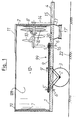
- FIG 1 is a mixing and distribution cart shown a box-shaped structure 12th with a flat bottom 1 with round ends.
- the height of the floor 1 protrudes to the right in FIG Drawbar 4 for connection to a towing vehicle.
- the box-shaped structure 12 on the floor 1 is on the drawbar side End by a semicircular in plan view curved end wall 7 and opposite at the other end limited by an identical, mirror-symmetrical end wall 7 '.
- the two end walls 7, 7 ' are through two longitudinal walls 120 connected, in the embodiment shown the front longitudinal wall is omitted to the To allow a look inside the structure 12.
- two wheels 3 are arranged, the are rotatably mounted on an axis 2 on the underside the bottom 1 is attached.
- a conveyor line 99 On the top of the bottom 1 is a conveyor line 99 arranged in the form of a chain conveyor consisting of a Chain 9 exists and moves in the direction of arrow 9 '.
- This Chain conveyor is an endless chain conveyor and runs around two spaced conveyor wheels 5 'and 5, the Rotation axes 6 'and 6 run perpendicular to the floor 1.
- the chain conveyor 9 has drivers, which will be used later of Figure 2 will be explained.
- the drawbar wheel 5 is via an angular gear 16, which is arranged in the area under the floor 1 is connected to a horizontal shaft 15 which thence to the free end of the drawbar 4.
- the shaft 15 carries a clutch, not shown Connection to a PTO of a towing vehicle.
- the shaft 15 carries a sprocket (not shown), that via a chain drive 14 to one above arranged, stored in the end wall 7 and about horizontal mixing shaft 8 leads in the direction of the arrow 8 'is rotatable, the chain drive 14 outside the drawbar-side end wall 7 is arranged.
- Mixing shaft 8 carries several regularly spaced apart Mixing paddle 10 perpendicular to the mixing shaft 8 stand out.
- the ends of the mixing blades 10 are at the front pointed like a prong.
- Opening 20 is arranged in the bottom 1 of the box-shaped structure 12. Below the opening 20 by a conformal Slider can be released and locked continuously is a tapered, funnel-like approach 17 available. A cross conveyor belt runs beneath this 17 'for the lateral discharge of the feed.
- the box-shaped structure 12 is smooth on the inside and on top provided with a reinforced edge 19.
- a removable Cover 11 e.g. a grid or mesh, arranged to prevent ejection of feed through the mixing blades 10.
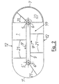
- Figure 2 shows a top view of the bottom 1, with all parts are omitted, which impair the overview, especially the shaft 8 with the wings 10.
- the two feed wheels 5 and 5 ' are also shown, around which the chain 9 of the chain conveyor in Arrow direction 9 'rotates when the drive over the shaft 15 is switched on.
- the drivers are on the chain 9 21 attached at regular intervals so that they can rotate around the conveyor wheels 5, 5 'and at the same time protrude as far as possible.
- the drivers 21 can be formed from angle or U profiles his.
- the length of the driver 21 and the outer contour of the bottom 1 are dimensioned so that the driver 21 at their Movement practically the entire area of the floor 1 sweep.
- Figure 3 of the drawing shows a second mixing and distribution car in cross section through its structure 12, wherein here an undercarriage existing under the structure 12 is not is shown.
- the structure 12 consists essentially from the flat floor 1, from its outer edge itself a sheet metal wall 120 extends upwards. At her top Edge 121 is the sheet metal wall 120 by triple folding towards the inside to a stable, but not towards the outside bulging stiffening edge.
- On top of the Structure 12 has a cover 11 that is at least over the front part of the structure 12, which is shown in Figure 3 is enough.
- the mixing shaft 8 On the semicircular one visible in the background front end wall 7 of the structure 12 is the mixing shaft 8 stored, which runs approximately horizontally and in the interior of the structure 12 protrudes. As Figure 3 illustrates, here is the mixing shaft 8 sideways to the right offset from the longitudinal center of the mixing and distribution wagon arranged. At the mixing shaft 8 are shown in the Embodiment three mixing blades 10 attached, the are each crescent-shaped and tapered. The three mixing blades 10 have different lengths, the length of the longest mixing blade 10 is chosen in this way is that its tip when the shaft 8 rotates in the direction of the rotation arrow 8 'just on the inner surfaces of the Construction 12 passes without touching it.
- the Mixing blades 10 are one behind the other on the mixing shaft 8 arranged with an axial distance, the shortest Mixing blades 10 furthest from the end wall 7 is arranged; the second longest mixing blade 10 follows afterwards and finally the longest mixing blade 10 is on next attached to the front wall 7.
- the mixing shaft 8 In the circumferential direction Looking at the mixing shaft 8 are the three mixing blades 10 arranged at a uniform distance of 120 °.
- Conveyor line 99 which is here also by a rotating Chain 9 is formed on the regular Distances running outward driver 21 attached are. Seen from above, the chain 9 runs against it Clockwise around, so that the driver 21 in the left half of the structure 12 towards the viewer and in the right half of the structure 12 away from the viewer move.
- cover 11 is also inclined Side surface trained to a jam of lining that is moved upwards by the mixing blades 10, safely excluded.
- Figure 4 of the drawing shows the front area of the floor 1 of the car from Figure 3 in a plan view, wherein the walls 120, the end wall 7 and the one mounted thereon Mixing shaft 8 with the mixing blades 10 not visible are.
- Driver 21 located at its inner end connected to the chain 9, for example welded are.
- Each driver 21 has one on its back Diagonal support 210, the foot end 211 loosely on the subsequent driver 21 at the foot end near the Chain 9 is supported.
- the diagonal supports 210 can do what not here visible, plastic pads are attached to the Reduce friction and wear.
- the roof-shaped from above Cover 91 visible in the area of the feed wheel 5 ends.
- the cover 91 is here with a slope 92 completed.
- the direction of the slope 92 is there chosen so that the tip 93 of the cover 91 on the Inlet side of the conveyor line 99, that is to say in FIG. 4 below, lies.
- FIG. 4 shows on the far right in the area of the semicircular end face of the bottom 1 the opening 20, which is used to eject the mixed feed down to one provided below, not shown here
- Cross conveyor belt is used.
- the opening 20 is by means of a flat slider attached below the floor 1 lockable and more or less as required fully releasable, the slider here too is not shown.
- the slide is in the longitudinal direction of the bottom 1 movable, which is preferably a hydraulic piston-cylinder arrangement is used.
- Figure 4 shows two squeegees 101, 102, which are mounted on the floor 1.
- the first Scraper strip 101 runs straight from chain 9 starting in the direction of movement 9 'of the conveyor line 99 viewed obliquely outwards in order to to strip adhesive feed outwards from the drivers 21.
- the squeegee serves the same purpose 102 in the area of the bottom 1 between the feed wheel 5 and the inner boundary 201 of the opening 20 and is curved.
- the inner boundary 201 of the opening 20 executed so that it is viewed in the direction of movement 9 ' steadily closer to the outer boundary 202 of the Opening 20 approaches.
- the inner boundary 201 of the opening 20 thus acts as a scraper or shear edge for from feed brought to the carriers 21 when the opening 20 is released and the feed is thrown down shall be.
- the mixing and Distribution car only at its opposite end or at both ends with a closable opening be provided.
Landscapes
- Life Sciences & Earth Sciences (AREA)
- Chemical & Material Sciences (AREA)
- Chemical Kinetics & Catalysis (AREA)
- Environmental Sciences (AREA)
- Birds (AREA)
- Animal Husbandry (AREA)
- Biodiversity & Conservation Biology (AREA)
- Mixers Of The Rotary Stirring Type (AREA)
- Housing For Livestock And Birds (AREA)
- Processing And Handling Of Plastics And Other Materials For Molding In General (AREA)
- Compositions Of Oxide Ceramics (AREA)
Description
- Figur 1
- einen Misch- und Verteilwagen in einer schematischen Seitenansicht,
- Figur 2
- eine schematische Draufsicht auf die Oberseite des Bodens des Wagens aus Figur 1,
- Figur 3
- einen zweiten Misch- und Verteilwagen im Querschnitt und
- Figur 4
- eine Draufsicht auf den Boden des Misch- und Verteilwagens aus Figur 3 in dessen vorderem Teil.
Claims (31)
- Misch- und Verteilwagen für Futter, mit einem kastenförmigen Aufbau (12) mit einem ebenen Boden (1), mit einem Fahrwerk (2) mit Rädern (3) und mit entweder einer Deichsel (4) zur lösbaren Verbindung mit einem Zugfahrzeug, insbesondere einem Traktor, oder einer eigenen Antriebseinheit, wobei auf der Oberseite des Bodens (1) parallel zu diesem ein Förderstrang (99) angeordnet ist, der um zwei in Längsrichtung des Misch- und Verteilwagens voneinander beabstandete Förderräder (5, 5') Drehachsen (6, 6') umläuft, wobei mindestens eines der Förderräder (5, 5') drehantreibbar ist und wobei
eine drehantreibbare, etwa horizontale Mischwelle (8) vorhanden ist, die mindestens einen Mischflügel (10) trägt, und
unter der Mischwelle (8) im Boden (1) eine Öffnung (20) angeordnet ist dadurch gekennzeichnet, daß die Drehachsen (6,6') der Förderräder (5,5') senkrecht zum Boden (1) verlaufen und daß die Mischwelle (8) an einer der beiden Stirnwände (7,7') des kastenförmigen Aufbaus (12) gelagert ist und der Mischflügel (10) von einem in den Aufbau ragenden Teil der Mischwelle (8) getragen wird daß die Öffnung (20) verschließbar ist. - Misch- und Verteilwagen nach Anspruch 1, dadurch gekennzeichnet, daß der Aufbau (12) Blechwände (120) umfaßt, die an ihrem oberen Rand (121) zumindest in geraden Wandbereichen ein- oder mehrfach zum Aufbauinneren hin abgekantet sind.
- Misch- und Verteilwagen nach Anspruch 2, dadurch gekennzeichnet, daß innenseitig am oberen Rand der Blechwände (120) zumindest im Bereich der Aufbau-Stirnseiten schrägstehende Verkleidungsbleche (122) zwischen der Innenkante der Abkantung(en) und der Wandinnenfläche angebracht sind.
- Misch- und Verteilwagen nach einem der vorhergehenden Ansprüche, dadurch gekennzeichnet, daß die Mischwelle (8) aus der Quermitte der Stirnwand (7) heraus in einer Richtung entgegen der Förderrichtung (9') des Förderstranges (99) seitwärts versetzt angeordnet ist.
- Misch- und Verteilwagen nach einem der vorhergehenden Ansprüche, dadurch gekennzeichnet, daß der Förderstrang (99) ein Kettenförderer mit einer Kette (9) ist, zwischen oder an deren Gliedern mehrere voneinander beabstandete, quer oder schräg zur Förderrichtung (9') nach außen weisende Mitnehmer (21) angeordnet sind, die beim Umlauf der Kette (9) die Oberseite des Bodens (1) zum größten Teil überstreichen.
- Misch- und Verteilwagen nach Anspruch 5, dadurch gekennzeichnet, daß an jedem Mitnehmer (21) rückseitig eine Diagonalstütze (210) angebracht ist, deren Fußende (211) zumindest in den zwischen den Förderrädern (5, 5') liegenden Förderstrangbereichen am Verbindungspunkt zwischen der Kette (9) und dem nachfolgenden Mitnehmer (21) lose abgestützt ist.
- Misch- und Verteilwagen nach Anspruch 5 oder 6, dadurch gekennzeichnet, daß die Mitnehmer (21) und gegebenenfalls deren Diagonalstützen (210) unterseitig eine auswechselbare Gleitauflage aus Kunststoff aufweisen.
- Misch- und Verteilwagen nach einem der Ansprüche 5 bis 7, dadurch gekennzeichnet, daß die Kette (9) zwischen den Förderrädern (5, 5') in einer zu den Mitnehmern (21) hin offenen Gleitschiene (90) geführt ist.
- Misch- und Verteilwagen nach Anspruch 8, dadurch gekennzeichnet, daß die Gleitschiene (90) ein C-Profil aus Kunststoff oder Holz oder ein mit Kunststoff oder Holz belegtes C-Profil ist.
- Misch- und Verteilwagen nach einem der Ansprüche 5 bis 9, dadurch gekennzeichnet, daß der vorlaufende und der rücklaufende Abschnitt der Kette (9) parallel zueinander längs der Mitte des Bodens (1) verlaufen und einen Abstand voneinander aufweisen, der maximal ¼ der Breite des Bodens (1) beträgt.
- Misch- und Verteilwagen nach Anspruch 10, dadurch gekennzeichnet, daß über den beiden Abschnitten der Kette (9) eine gemeinsame, im Querschnitt dachförmige Abdeckung (91) angebracht ist.
- Misch- und Verteilwagen nach Anspruch 11, dadurch gekennzeichnet, daß die Abdeckung (91) an ihren nahe oder über den Förderrädern (5, 5') liegenden Enden je einen schrägen Abschluß (92) aufweist, wobei die Spitze (93) der Schräge an der Zulaufseite des Förderstranges (99) liegt.
- Misch- und Verteilwagen nach einem der vorhergehenden Ansprüche, dadurch gekennzeichnet, daß an dem in den Aufbau (12) ragenden Teil der Mischwelle (8) mehrere regelmäßig beabstandete, senkrecht zur Mischwelle (8) stehende Mischflügel (10) angeordnet sind, die bei Drehung der Mischwelle (8) nahe am Boden (1) entlangstreichen.
- Misch- und Verteilwagen nach Anspruch 13, dadurch gekennzeichnet, daß die Mischwelle (8) mit ihrem freien Ende bis in den Bereich nahe über dem benachbarten Förderrad (5) reicht und daß in Mischwellenrichtung betrachtet der äußere Mischflügel (10) über dem Förderrad (5) umläuft.
- Misch- und Verteilwagen nach Anspruch 13 oder 14, dadurch gekennzeichnet, daß mindestens drei in Umfangsrichtung der Mischwelle (8) gleichmäßig versetzte Mischflügel (10) unterschiedlicher Länge vorgesehen sind.
- Misch- und Verteilwagen nach einem der Ansprüche 13 bis 15, dadurch gekennzeichnet, daß die Länge der Mischflügel (10) vom freien Ende der Mischwelle (8) zur diese tragenden Stirnwand (7) hin zunimmt.
- Misch- und Verteilwagen nach einem der Ansprüche 13 bis 16, dadurch gekennzeichnet, daß die Mischflügel (10) sichelförmig gekrümmt und zugespitzt sind, wobei die Krümmung in Drehrichtung (8') der Mischwelle (8) weist.
- Misch- und Verteilwagen nach einem der Ansprüche 13 bis 17, dadurch gekennzeichnet, daß der Übergang vom Boden (1) zu der die Mischwelle (8) tragenden Stirnwand (7) zumindest im Wirkungsbereich der Mischflügel (10) abgeschrägt oder ausgerundet ist.
- Misch- und Verteilwagen nach einem der Ansprüche 13 bis 18, dadurch gekennzeichnet, daß die Bewegung des Förderstranges (99) und die Drehung der Mischwelle (8) in einem solchen Verhältnis erfolgen, daß bei Bewegung des Förderstranges (99) um einen Mitnehmerabstand die Mischwelle (8) eine ganze Umdrehung oder mehr ausführt.
- Misch- und Verteilwagen nach einem der vorhergehenden Ansprüche, dadurch gekennzeichnet, daß die Mischwelle (8) über einen Kettentrieb (14) von einer weiteren, etwa horizontalen Welle (15) drehbar ist, die etwa in der Längsmittelachse des Bodens (1) des kastenförmigen Aufbaus (12) unterhalb der Förderräder (5, 5') verläuft, wobei die weitere Welle (15) an ihrem einen Ende über ein Winkelgetriebe (16) mit einem der Förderräder (5, 5') gekoppelt ist und an ihrem anderen Ende entweder eine Kupplung trägt, die mit einer Zapfwelle eines Zugfahrzeugs, insbesondere Traktors, verbindbar ist oder unmittelbar mit der eigenen Antriebseinheit des Wagens verbunden ist.
- Misch- und Verteilwagen nach einem der vorhergehenden Ansprüche, dadurch gekennzeichnet, daß die beiden Stirnwände (7, 7') jeweils einen halbkreisförmigen Grundriß aufweisen, daß die verschließbare Öffnung (20) im Boden (1) etwa halbkreisförmig parallel zur einen Stirnwand (7) verläuft und daß die Öffnung (20) durch einen formangepaßten Schieber verschließbar und stufenlos freigebbar ist.
- Misch- und Verteilwagen nach Anspruch 21, dadurch gekennzeichnet, daß die wandabgewandte Begrenzung (201) der Öffnung (20) in Bewegungsrichtung (9') des Förderstranges (99) betrachtet stetig näher an die wandnahe Begrenzung (202) der Öffnung (20) heranläuft.
- Misch- und Verteilwagen nach einem der vorhergehenden Ansprüche, dadurch gekennzeichnet, daß eine Achse (2) mit zwei Rädern (3) vorhanden ist, die unter dem Boden (1) zwischen den beiden Förderrädern (5, 5') nahe dem einen Förderrad (5') angeordnet ist.
- Misch- und Verteilwagen nach einem der vorhergehenden Ansprüche, dadurch gekennzeichnet, daß der kastenförmige Aufbau (12) oben zumindest im Bereich oberhalb der Mischwelle (8) eine entfernbare Abdeckung (11) aufweist.
- Misch- und Verteilwagen nach einem der vorhergehenden Ansprüche, dadurch gekennzeichnet, daß die Kette (9) in Längsrichtung des Misch- und Verteilwagens durch eine Spannvorrichtung vorspannbar ist, wobei die Spannvorrichtung mindestens eine mechanische oder pneumatische oder hydraulische Feder aufweist.
- Misch- und Verteilwagen nach einem der Ansprüche 5 bis 25, dadurch gekennzeichnet, daß die Mitnehmer (21) jeweils ein im Querschnitt winkel- oder U-förmiges Profil aufweisen und/oder an ihren Enden elastisch-flexible Abstreifer, vorzugsweise aus Gummi, tragen.
- Misch- und Verteilwagen nach einem der Ansprüche 5 bis 26, dadurch gekennzeichnet, daß auf dem Boden (1) mehrere Abstreifleisten (101, 102) zum streifenden Eingriff mit den Mitnehmern (21) angeordnet sind und/oder daß die Öffnung (20) in ihrem Randbereich innenseitig als Scherkante ausgebildet ist.
- Misch- und Verteilwagen nach Anspruch 27, dadurch gekennzeichnet, daß die Abstreifleisten (101, 102) in Bewegungsrichtung (9') des Förderstranges (99) betrachtet von der Kette (9) aus schräg nach außen weisen.
- Misch- und Verteilwagen nach Anspruch 27 oder 28, dadurch gekennzeichnet, daß im Bereich des Bodens (1) innenseitig von der Öffnung (20) mindestens eine gekrümmt verlaufende Abstreifleiste (102) vorgesehen ist, die tangential an die wandabgewandte Begrenzung (201) der Öffnung (20) läuft.
- Misch- und Verteilwagen nach Anspruch 27 oder 28 oder 29, dadurch gekennzeichnet, daß die Abstreifleisten (101, 102) aus Metall oder Kunststoff bestehen und auswechselbar auf dem Boden (1) angebracht sind.
- Misch- und Verteilwagen nach einem der vorhergehenden Ansprüche, dadurch gekennzeichnet, daß zusätzlich zu oder anstatt der im Boden (1) unter der Mischwelle (8) vorgesehenen verschließbaren Öffnung (20) eine verschließbare Öffnung nahe der entgegengesetzten, mischwellenfernen Stirnwand (7') des Aufbaus (12) vorgesehen ist.
Applications Claiming Priority (4)
| Application Number | Priority Date | Filing Date | Title |
|---|---|---|---|
| DE19725888 | 1997-06-19 | ||
| DE19725888A DE19725888A1 (de) | 1997-06-19 | 1997-06-19 | Misch- und Verteilwagen für Futter |
| DE19806656 | 1998-02-18 | ||
| DE19806656A DE19806656A1 (de) | 1997-06-19 | 1998-02-18 | Misch- und Verteilwagen für Futter |
Publications (3)
| Publication Number | Publication Date |
|---|---|
| EP0885559A2 EP0885559A2 (de) | 1998-12-23 |
| EP0885559A3 EP0885559A3 (de) | 2000-06-21 |
| EP0885559B1 true EP0885559B1 (de) | 2003-02-12 |
Family
ID=26037562
Family Applications (1)
| Application Number | Title | Priority Date | Filing Date |
|---|---|---|---|
| EP98111175A Expired - Lifetime EP0885559B1 (de) | 1997-06-19 | 1998-06-18 | Misch- und Verteilwagen für Futter |
Country Status (3)
| Country | Link |
|---|---|
| EP (1) | EP0885559B1 (de) |
| AT (1) | ATE232355T1 (de) |
| DE (2) | DE19806656A1 (de) |
Families Citing this family (6)
| Publication number | Priority date | Publication date | Assignee | Title |
|---|---|---|---|---|
| DE19830381A1 (de) | 1998-07-08 | 2000-01-20 | Von Der Heide Maschinenbau Gmb | Kettenförderer |
| DE202009004733U1 (de) * | 2009-04-24 | 2009-06-25 | Eckart, Gerhard | Vorrichtung zum Mischen von Schüttgut |
| DE202010016420U1 (de) * | 2010-12-09 | 2011-05-05 | B. Strautmann & Söhne GmbH u. Co. KG | Mischbehälter für die Aufnahme von Viehfutter |
| RU2583702C1 (ru) * | 2015-06-01 | 2016-05-10 | Федеральное государственное бюджетное научное учреждение Всероссийский научно-исследовательский институт механизации животноводства, ФГБНУ ВНИИМЖ | Мобильный кормораздатчик |
| CN107494293A (zh) * | 2017-08-23 | 2017-12-22 | 益福光(天津)电子科技有限公司 | 一种高端智能机器人 |
| CN115428741B (zh) * | 2022-09-26 | 2023-10-27 | 佳木斯大学 | 一种无死角利清刷的三转位猪食槽槽形及其型线设计方法 |
Family Cites Families (4)
| Publication number | Priority date | Publication date | Assignee | Title |
|---|---|---|---|---|
| IT209372Z2 (it) * | 1986-10-30 | 1988-10-05 | Caravaggi Gian Lorenzo | Macchina per sminuzzare balle di paglia, fieno e simili. |
| FR2678695B3 (fr) * | 1991-07-03 | 1993-10-15 | Crms | Dispositif d'entrainement selectif d'un arbre de sortie au moyen d'un arbre moteur et machine pour distribuer les fourrages, qui en est equipee. |
| DE29511311U1 (de) * | 1995-07-13 | 1995-09-14 | B. Strautmann & Söhne GmbH u. Co, 49196 Bad Laer | Futterverteilwagen |
| EP0754405A1 (de) * | 1995-07-21 | 1997-01-22 | Tiziano Faccia | Verbesserte Tierfutterschneide- und -mischvorrichtung |
-
1998
- 1998-02-18 DE DE19806656A patent/DE19806656A1/de not_active Withdrawn
- 1998-06-18 DE DE59807155T patent/DE59807155D1/de not_active Expired - Fee Related
- 1998-06-18 AT AT98111175T patent/ATE232355T1/de not_active IP Right Cessation
- 1998-06-18 EP EP98111175A patent/EP0885559B1/de not_active Expired - Lifetime
Also Published As
| Publication number | Publication date |
|---|---|
| ATE232355T1 (de) | 2003-02-15 |
| DE19806656A1 (de) | 1999-08-19 |
| EP0885559A2 (de) | 1998-12-23 |
| DE59807155D1 (de) | 2003-03-20 |
| EP0885559A3 (de) | 2000-06-21 |
Similar Documents
| Publication | Publication Date | Title |
|---|---|---|
| EP2522545B1 (de) | Laderaum eines Fahrzeugs, insbesondere eines Transportwagens, Laderaumvorrichtung und ein Transportwagen | |
| EP0885559B1 (de) | Misch- und Verteilwagen für Futter | |
| EP0223004B1 (de) | Verfahrbares Zerkleinerungs- und Austragsgerät für Silageblöcke | |
| DE3419997A1 (de) | Futtermischwagen | |
| DE2743739A1 (de) | Streumaschine, insbesondere stalldungstreuer | |
| EP0102406A1 (de) | Aufnahme- und Verteilungswagen für Silage, Stroh und dgl. Gut | |
| EP2397425B1 (de) | Mobile Überladestation zum Überladen von Schüttgut | |
| DE2706803A1 (de) | Futterwagen | |
| EP2058172A1 (de) | Laderaumaufbau mit bewegbarer Stirnwand und Transportwagen mit einem solchen Aufbau | |
| DE1166700B (de) | Lastfahrzeug mit Schrappeinrichtung | |
| DE2426025A1 (de) | Vorrichtung zur entnahme von viehfutter aus einem silo | |
| DE3033533A1 (de) | Streuer fuer stalldung u.ae. massen | |
| DE2638963C2 (de) | Rübenerntemaschine | |
| DE19725888A1 (de) | Misch- und Verteilwagen für Futter | |
| DE1755729A1 (de) | Landwirtschaftlicher wagen | |
| DE3051007C2 (de) | Landwirtschaftliches Ladefahrzeug mit einer an seinem einen Ende angeordneten Dosiereinrichtung | |
| DE3800605A1 (de) | Anlage zum auf- und abbau von mischbetthalden | |
| DE20304321U1 (de) | Mischgerät | |
| DE886875C (de) | Entlade- und Foerdereinrichtung fuer Ackerwagen | |
| DE3023653C2 (de) | Landwirtschaftliches Ladefahrzeug mit einer an seinem einen Ende angeordneten Dosiereinrichtung | |
| EP0654299A1 (de) | Misch- und Verteilvorrichtung für Viehfutter | |
| DE1949848A1 (de) | Selbsttaetig entladendes Fahrzeug | |
| DE3543312A1 (de) | Entspeicherungsgeraet fuer schuettguthalden | |
| DE29900199U1 (de) | Vorrichtung zum Mischen und Verteilen von Schüttgütern | |
| DE1811095B2 (de) | Landwirtschaftlicher Wagen |
Legal Events
| Date | Code | Title | Description |
|---|---|---|---|
| PUAI | Public reference made under article 153(3) epc to a published international application that has entered the european phase |
Free format text: ORIGINAL CODE: 0009012 |
|
| AK | Designated contracting states |
Kind code of ref document: A2 Designated state(s): AT DE FR GB IE IT NL SE |
|
| AX | Request for extension of the european patent |
Free format text: AL;LT;LV;MK;RO;SI |
|
| PUAL | Search report despatched |
Free format text: ORIGINAL CODE: 0009013 |
|
| AK | Designated contracting states |
Kind code of ref document: A3 Designated state(s): AT BE CH CY DE DK ES FI FR GB GR IE IT LI LU MC NL PT SE |
|
| AX | Request for extension of the european patent |
Free format text: AL;LT;LV;MK;RO;SI |
|
| RIC1 | Information provided on ipc code assigned before grant |
Free format text: 7A 01K 5/00 A, 7A 01F 29/00 B |
|
| 17P | Request for examination filed |
Effective date: 20001220 |
|
| AKX | Designation fees paid |
Free format text: AT DE FR GB IE IT NL SE |
|
| GRAH | Despatch of communication of intention to grant a patent |
Free format text: ORIGINAL CODE: EPIDOS IGRA |
|
| GRAH | Despatch of communication of intention to grant a patent |
Free format text: ORIGINAL CODE: EPIDOS IGRA |
|
| GRAA | (expected) grant |
Free format text: ORIGINAL CODE: 0009210 |
|
| AK | Designated contracting states |
Designated state(s): AT DE FR GB IE IT NL SE |
|
| PG25 | Lapsed in a contracting state [announced via postgrant information from national office to epo] |
Ref country code: NL Free format text: LAPSE BECAUSE OF FAILURE TO SUBMIT A TRANSLATION OF THE DESCRIPTION OR TO PAY THE FEE WITHIN THE PRESCRIBED TIME-LIMIT Effective date: 20030212 Ref country code: IT Free format text: LAPSE BECAUSE OF FAILURE TO SUBMIT A TRANSLATION OF THE DESCRIPTION OR TO PAY THE FEE WITHIN THE PRESCRIBED TIME-LIMIT;WARNING: LAPSES OF ITALIAN PATENTS WITH EFFECTIVE DATE BEFORE 2007 MAY HAVE OCCURRED AT ANY TIME BEFORE 2007. THE CORRECT EFFECTIVE DATE MAY BE DIFFERENT FROM THE ONE RECORDED. Effective date: 20030212 Ref country code: IE Free format text: LAPSE BECAUSE OF FAILURE TO SUBMIT A TRANSLATION OF THE DESCRIPTION OR TO PAY THE FEE WITHIN THE PRESCRIBED TIME-LIMIT Effective date: 20030212 Ref country code: GB Free format text: LAPSE BECAUSE OF FAILURE TO SUBMIT A TRANSLATION OF THE DESCRIPTION OR TO PAY THE FEE WITHIN THE PRESCRIBED TIME-LIMIT Effective date: 20030212 Ref country code: FR Free format text: LAPSE BECAUSE OF FAILURE TO SUBMIT A TRANSLATION OF THE DESCRIPTION OR TO PAY THE FEE WITHIN THE PRESCRIBED TIME-LIMIT Effective date: 20030212 |
|
| REG | Reference to a national code |
Ref country code: GB Ref legal event code: FG4D Free format text: NOT ENGLISH |
|
| REF | Corresponds to: |
Ref document number: 59807155 Country of ref document: DE Date of ref document: 20030320 Kind code of ref document: P |
|
| PG25 | Lapsed in a contracting state [announced via postgrant information from national office to epo] |
Ref country code: SE Free format text: LAPSE BECAUSE OF FAILURE TO SUBMIT A TRANSLATION OF THE DESCRIPTION OR TO PAY THE FEE WITHIN THE PRESCRIBED TIME-LIMIT Effective date: 20030512 |
|
| PG25 | Lapsed in a contracting state [announced via postgrant information from national office to epo] |
Ref country code: AT Free format text: LAPSE BECAUSE OF NON-PAYMENT OF DUE FEES Effective date: 20030618 |
|
| NLV1 | Nl: lapsed or annulled due to failure to fulfill the requirements of art. 29p and 29m of the patents act | ||
| REG | Reference to a national code |
Ref country code: IE Ref legal event code: FG4D Free format text: GERMAN |
|
| GBV | Gb: ep patent (uk) treated as always having been void in accordance with gb section 77(7)/1977 [no translation filed] |
Effective date: 20030212 |
|
| REG | Reference to a national code |
Ref country code: IE Ref legal event code: FD4D Ref document number: 0885559E Country of ref document: IE |
|
| PLBE | No opposition filed within time limit |
Free format text: ORIGINAL CODE: 0009261 |
|
| STAA | Information on the status of an ep patent application or granted ep patent |
Free format text: STATUS: NO OPPOSITION FILED WITHIN TIME LIMIT |
|
| PG25 | Lapsed in a contracting state [announced via postgrant information from national office to epo] |
Ref country code: DE Free format text: LAPSE BECAUSE OF NON-PAYMENT OF DUE FEES Effective date: 20040101 |
|
| EN | Fr: translation not filed | ||
| 26N | No opposition filed |
Effective date: 20031113 |