EP0885559B1 - Wagon for distributing and mixing animal feed - Google Patents
Wagon for distributing and mixing animal feed Download PDFInfo
- Publication number
- EP0885559B1 EP0885559B1 EP98111175A EP98111175A EP0885559B1 EP 0885559 B1 EP0885559 B1 EP 0885559B1 EP 98111175 A EP98111175 A EP 98111175A EP 98111175 A EP98111175 A EP 98111175A EP 0885559 B1 EP0885559 B1 EP 0885559B1
- Authority
- EP
- European Patent Office
- Prior art keywords
- mixing
- wagon
- distributing
- floor
- shaft
- Prior art date
- Legal status (The legal status is an assumption and is not a legal conclusion. Google has not performed a legal analysis and makes no representation as to the accuracy of the status listed.)
- Expired - Lifetime
Links
Images


Classifications
-
- A—HUMAN NECESSITIES
- A01—AGRICULTURE; FORESTRY; ANIMAL HUSBANDRY; HUNTING; TRAPPING; FISHING
- A01K—ANIMAL HUSBANDRY; CARE OF BIRDS, FISHES, INSECTS; FISHING; REARING OR BREEDING ANIMALS, NOT OTHERWISE PROVIDED FOR; NEW BREEDS OF ANIMALS
- A01K5/00—Feeding devices for stock or game ; Feeding wagons; Feeding stacks
- A01K5/001—Fodder distributors with mixer or shredder
- A01K5/002—Fodder distributors with mixer or shredder with mixing or shredding element rotating on horizontal axis
-
- B—PERFORMING OPERATIONS; TRANSPORTING
- B01—PHYSICAL OR CHEMICAL PROCESSES OR APPARATUS IN GENERAL
- B01F—MIXING, e.g. DISSOLVING, EMULSIFYING OR DISPERSING
- B01F27/00—Mixers with rotary stirring devices in fixed receptacles; Kneaders
- B01F27/60—Mixers with rotary stirring devices in fixed receptacles; Kneaders with stirrers rotating about a horizontal or inclined axis
-
- B—PERFORMING OPERATIONS; TRANSPORTING
- B01—PHYSICAL OR CHEMICAL PROCESSES OR APPARATUS IN GENERAL
- B01F—MIXING, e.g. DISSOLVING, EMULSIFYING OR DISPERSING
- B01F33/00—Other mixers; Mixing plants; Combinations of mixers
- B01F33/50—Movable or transportable mixing devices or plants
- B01F33/502—Vehicle-mounted mixing devices
- B01F33/5023—Vehicle-mounted mixing devices the vehicle being a trailer which is hand moved or coupled to self-propelling vehicles
-
- B—PERFORMING OPERATIONS; TRANSPORTING
- B01—PHYSICAL OR CHEMICAL PROCESSES OR APPARATUS IN GENERAL
- B01F—MIXING, e.g. DISSOLVING, EMULSIFYING OR DISPERSING
- B01F2101/00—Mixing characterised by the nature of the mixed materials or by the application field
- B01F2101/06—Mixing of food ingredients
- B01F2101/18—Mixing animal food ingredients
-
- B—PERFORMING OPERATIONS; TRANSPORTING
- B01—PHYSICAL OR CHEMICAL PROCESSES OR APPARATUS IN GENERAL
- B01F—MIXING, e.g. DISSOLVING, EMULSIFYING OR DISPERSING
- B01F33/00—Other mixers; Mixing plants; Combinations of mixers
- B01F33/50—Movable or transportable mixing devices or plants
- B01F33/502—Vehicle-mounted mixing devices
Definitions
- the present invention relates to a mixing and distribution wagon for feed, according to the preamble of the claim 1.
- a carriage is known from DE 295 11 311 U.
- Such cars have been in practical operation known for a long time. They are primarily used for transportation of feed, for example green or dry feed or Silage, and can also be used to extend, i.e. also to distribute of such feed. If in addition to the known mixing and distribution car Industrial truck, such as a wheel loader, is also by adding mixing components one after the other some mixing in the box-shaped Construction possible, but for this large drive powers and therefore very strong drives or towing vehicles are necessary.
- the embodiment according to claim 3 ensures that in feed moving the wagon as it moves up has no storage space in the area of the fold; much more becomes the ascending through the cladding sheets Lining is drained inwards and then falls under Gravity back into the interior of the body.
- the measure specified in claim 4 ensures that the mixing shaft with its at least one mixing blade the feed supplied by means of the conveyor line already detected before this on the mixed shaft carrying End wall can jam. This will drive the power requirement for the rotation of the mixing shaft on Minimum reduced without that with the mixing shaft and their at least one mixing blade achievable mixing effect is reduced.
- the conveyor line Chain conveyor with a chain is between or on its Link several, spaced or transverse Drivers pointing outwards to the conveying direction are arranged, the top of the chain covering the floor for the most part.
- the chain is according to claim 8 preferably guided in slide rails.
- the slide rails can, for example, according to claim 9 as a C-profile made of plastic or wood or with plastic or wooden support.
- This cover guides the feed simply by gravity sideways where the feed returns to the mixing motion of the conveyor line is included.
- the cover due to its roof shape when loading for example a relatively solid silage block making sure that it hits the cover when it hits it breaks into at least two parts, each for itself are easier to shred than one complete silage block would be the case.
- the free end of the mixing shaft is advantageously sufficient up to the area above the neighboring feed wheel, whereby the outer mixing blade is viewed in the direction of the mixing shaft rotates above the conveyor wheel adjacent to the mixing shaft. This ensures that the feed flow in its entire cross-section in the sphere of activity the mixing blade arrives.
- the length of the mixing blades from the free end of the mixing shaft increases towards this supporting end wall.
- the mixing blades are crescent-shaped and tapered are, the curvature in the direction of rotation of the mixing shaft has. In this way, the mixing blades grip like a shovel into the feed and lift it off the ground towards the top, without causing the forage to compress and thus a strong braking of the mixing blades can come.
- the transition from the floor to the one supporting the mixing shaft Front wall at least in the effective area of the mixing blades beveled or rounded.
- the mixing shaft via a chain drive from another, approximately horizontal Shaft rotatable approximately in the longitudinal central axis the bottom of the box-shaped structure below the conveyor wheels runs, with the further wave on her one end via an angular gear with one of the conveyors is coupled and at its other end either carries a clutch with a PTO of a towing vehicle, especially tractor, is connectable or directly with the car's own drive unit connected is.
- This is not a separate drive for the two grants, i.e. the conveyor line and the Mixing shaft of the mixing and distribution wagon required.
- the branching of the initiated torque over a known as such chain drive and about one as well Known angular gear represents a structurally simple and robust solution.
- the two end walls expediently each have one semicircular plan and runs the closable Opening in the bottom approximately parallel in a semicircle to one end wall, the opening through a shape-adjustable slide lockable and infinitely variable can be released. Due to the location and shape of the opening a practically complete and easy to dose The body is emptied when the chain conveyor moves and given the mixing blade. When transporting feed in the box-shaped structure, the opening is closed; the drive of the chain conveyor and the mixing shaft can then be switched off or - for mixing during the trip - already switched on.
- an axis is included two wheels are present under the floor between the two conveyor wheels near the one, preferably the the feed wheel facing away from the drawbar is arranged. hereby becomes a particularly simple and therefore inexpensive Construction with favorable load distribution on axles and Drawbar reached.
- the box-shaped structure of the mixing and invention Distribution trolley is used above in many applications can remain open for most of its length, thereby loading is advantageously simplified. It is but advantageous, at least in the area above the Mixing shaft with the mixing blades a removable cover to be thrown out when mixing to avoid of feed.
- the tensioning device preferably at least one mechanical or pneumatic or. has hydraulic spring and preferably protected is located under the floor.
- the squeegees are a wearing part, these are preferably made of metal or plastic and are conveniently interchangeably attached to the floor.
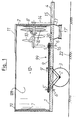
- FIG 1 is a mixing and distribution cart shown a box-shaped structure 12th with a flat bottom 1 with round ends.
- the height of the floor 1 protrudes to the right in FIG Drawbar 4 for connection to a towing vehicle.
- the box-shaped structure 12 on the floor 1 is on the drawbar side End by a semicircular in plan view curved end wall 7 and opposite at the other end limited by an identical, mirror-symmetrical end wall 7 '.
- the two end walls 7, 7 ' are through two longitudinal walls 120 connected, in the embodiment shown the front longitudinal wall is omitted to the To allow a look inside the structure 12.
- two wheels 3 are arranged, the are rotatably mounted on an axis 2 on the underside the bottom 1 is attached.
- a conveyor line 99 On the top of the bottom 1 is a conveyor line 99 arranged in the form of a chain conveyor consisting of a Chain 9 exists and moves in the direction of arrow 9 '.
- This Chain conveyor is an endless chain conveyor and runs around two spaced conveyor wheels 5 'and 5, the Rotation axes 6 'and 6 run perpendicular to the floor 1.
- the chain conveyor 9 has drivers, which will be used later of Figure 2 will be explained.
- the drawbar wheel 5 is via an angular gear 16, which is arranged in the area under the floor 1 is connected to a horizontal shaft 15 which thence to the free end of the drawbar 4.
- the shaft 15 carries a clutch, not shown Connection to a PTO of a towing vehicle.
- the shaft 15 carries a sprocket (not shown), that via a chain drive 14 to one above arranged, stored in the end wall 7 and about horizontal mixing shaft 8 leads in the direction of the arrow 8 'is rotatable, the chain drive 14 outside the drawbar-side end wall 7 is arranged.
- Mixing shaft 8 carries several regularly spaced apart Mixing paddle 10 perpendicular to the mixing shaft 8 stand out.
- the ends of the mixing blades 10 are at the front pointed like a prong.
- Opening 20 is arranged in the bottom 1 of the box-shaped structure 12. Below the opening 20 by a conformal Slider can be released and locked continuously is a tapered, funnel-like approach 17 available. A cross conveyor belt runs beneath this 17 'for the lateral discharge of the feed.
- the box-shaped structure 12 is smooth on the inside and on top provided with a reinforced edge 19.
- a removable Cover 11 e.g. a grid or mesh, arranged to prevent ejection of feed through the mixing blades 10.
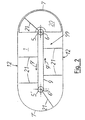
- Figure 2 shows a top view of the bottom 1, with all parts are omitted, which impair the overview, especially the shaft 8 with the wings 10.
- the two feed wheels 5 and 5 ' are also shown, around which the chain 9 of the chain conveyor in Arrow direction 9 'rotates when the drive over the shaft 15 is switched on.
- the drivers are on the chain 9 21 attached at regular intervals so that they can rotate around the conveyor wheels 5, 5 'and at the same time protrude as far as possible.
- the drivers 21 can be formed from angle or U profiles his.
- the length of the driver 21 and the outer contour of the bottom 1 are dimensioned so that the driver 21 at their Movement practically the entire area of the floor 1 sweep.
- Figure 3 of the drawing shows a second mixing and distribution car in cross section through its structure 12, wherein here an undercarriage existing under the structure 12 is not is shown.
- the structure 12 consists essentially from the flat floor 1, from its outer edge itself a sheet metal wall 120 extends upwards. At her top Edge 121 is the sheet metal wall 120 by triple folding towards the inside to a stable, but not towards the outside bulging stiffening edge.
- On top of the Structure 12 has a cover 11 that is at least over the front part of the structure 12, which is shown in Figure 3 is enough.
- the mixing shaft 8 On the semicircular one visible in the background front end wall 7 of the structure 12 is the mixing shaft 8 stored, which runs approximately horizontally and in the interior of the structure 12 protrudes. As Figure 3 illustrates, here is the mixing shaft 8 sideways to the right offset from the longitudinal center of the mixing and distribution wagon arranged. At the mixing shaft 8 are shown in the Embodiment three mixing blades 10 attached, the are each crescent-shaped and tapered. The three mixing blades 10 have different lengths, the length of the longest mixing blade 10 is chosen in this way is that its tip when the shaft 8 rotates in the direction of the rotation arrow 8 'just on the inner surfaces of the Construction 12 passes without touching it.
- the Mixing blades 10 are one behind the other on the mixing shaft 8 arranged with an axial distance, the shortest Mixing blades 10 furthest from the end wall 7 is arranged; the second longest mixing blade 10 follows afterwards and finally the longest mixing blade 10 is on next attached to the front wall 7.
- the mixing shaft 8 In the circumferential direction Looking at the mixing shaft 8 are the three mixing blades 10 arranged at a uniform distance of 120 °.
- Conveyor line 99 which is here also by a rotating Chain 9 is formed on the regular Distances running outward driver 21 attached are. Seen from above, the chain 9 runs against it Clockwise around, so that the driver 21 in the left half of the structure 12 towards the viewer and in the right half of the structure 12 away from the viewer move.
- cover 11 is also inclined Side surface trained to a jam of lining that is moved upwards by the mixing blades 10, safely excluded.
- Figure 4 of the drawing shows the front area of the floor 1 of the car from Figure 3 in a plan view, wherein the walls 120, the end wall 7 and the one mounted thereon Mixing shaft 8 with the mixing blades 10 not visible are.
- Driver 21 located at its inner end connected to the chain 9, for example welded are.
- Each driver 21 has one on its back Diagonal support 210, the foot end 211 loosely on the subsequent driver 21 at the foot end near the Chain 9 is supported.
- the diagonal supports 210 can do what not here visible, plastic pads are attached to the Reduce friction and wear.
- the roof-shaped from above Cover 91 visible in the area of the feed wheel 5 ends.
- the cover 91 is here with a slope 92 completed.
- the direction of the slope 92 is there chosen so that the tip 93 of the cover 91 on the Inlet side of the conveyor line 99, that is to say in FIG. 4 below, lies.
- FIG. 4 shows on the far right in the area of the semicircular end face of the bottom 1 the opening 20, which is used to eject the mixed feed down to one provided below, not shown here
- Cross conveyor belt is used.
- the opening 20 is by means of a flat slider attached below the floor 1 lockable and more or less as required fully releasable, the slider here too is not shown.
- the slide is in the longitudinal direction of the bottom 1 movable, which is preferably a hydraulic piston-cylinder arrangement is used.
- Figure 4 shows two squeegees 101, 102, which are mounted on the floor 1.
- the first Scraper strip 101 runs straight from chain 9 starting in the direction of movement 9 'of the conveyor line 99 viewed obliquely outwards in order to to strip adhesive feed outwards from the drivers 21.
- the squeegee serves the same purpose 102 in the area of the bottom 1 between the feed wheel 5 and the inner boundary 201 of the opening 20 and is curved.
- the inner boundary 201 of the opening 20 executed so that it is viewed in the direction of movement 9 ' steadily closer to the outer boundary 202 of the Opening 20 approaches.
- the inner boundary 201 of the opening 20 thus acts as a scraper or shear edge for from feed brought to the carriers 21 when the opening 20 is released and the feed is thrown down shall be.
- the mixing and Distribution car only at its opposite end or at both ends with a closable opening be provided.
Abstract
Description
Die vorliegende Erfindung betrifft einen Misch- und Verteilwagen
für Futter, nach dem Oberbegriff des Patentanspruchs
1. Ein derartiger Wagen ist aus DE 295 11 311 U bekannt.The present invention relates to a mixing and distribution wagon
for feed, according to the preamble of the
Derartige Wagen sind aus dem praktischen Betrieb seit langem bekannt. Sie dienen in erster Linie dem Transport von Futter, beispielsweise Grün- oder Trockenfutter oder Silage, und können auch zum Ausfahren, also auch zum Verteilen von solchem Futter, eingesetzt werden. Wenn man zusätzlich zu dem bekannten Misch- und Verteilwagen ein Flurförderfahrzeug, wie einen Radlader, einsetzt, ist auch durch nacheinander erfolgendes Einbringen von Mischkomponenten ein gewisses Vermischen in dem kastenförmigen Aufbau möglich, wobei hierfür aber große Antriebsleistungen und somit sehr starke Antriebe oder Zugfahrzeuge nötig sind.Such cars have been in practical operation known for a long time. They are primarily used for transportation of feed, for example green or dry feed or Silage, and can also be used to extend, i.e. also to distribute of such feed. If in addition to the known mixing and distribution car Industrial truck, such as a wheel loader, is also by adding mixing components one after the other some mixing in the box-shaped Construction possible, but for this large drive powers and therefore very strong drives or towing vehicles are necessary.
Es ist ein Nachteil der bekannten Wagen, daß die Mischund Verteilvorgänge sehr hohe Antriebsleistungen verlangen oder nur durch zusätzlichen Einsatz von Arbeitskräften oder durch weitere motorgetriebene Geräte, wie Flurförderfahrzeuge, möglich sind.It is a disadvantage of the known cars that the mixing and Distribution processes require very high drive powers or only through additional labor or by other motor-driven devices, such as industrial trucks, possible are.
Es ist die Aufgabe der vorliegenden Erfindung, einen Misch- und Verteilwagen für Futter zu schaffen, bei dem das Mischen, Transportieren und Verteilen von Futter mit einer niedrigen Antriebsleistung und ohne zusätzliche Arbeitskräfte außer dem Fahrer eines Zugfahrzeugs oder des angetriebenen Misch- und Verteilwagens bequem und zuverlässig möglich ist.It is the object of the present invention, one To create mixing and distribution wagons for fodder where mixing, transporting and distributing feed with a low drive power and without additional Workers other than the driver of a towing vehicle or of the powered mixing and distribution wagon convenient and is reliably possible.
Die Lösung der Aufgabe erfolgt mit einem Misch- und Verteilwagen
der eingangs genannten Art mit den kennzeichnenden
Merkmalen des Patentanspruchs 1.The task is solved with a mixing and distribution cart
of the type mentioned above with the characteristic
Features of
Bei dem erfindungsgemäßen Misch- und Verteilwagen wir die vorteilhafte Wirkung erreicht, daß bei geschlossener Öffnung durch den auf dem Boden umlaufenden Förderstrang einerseits und den oder die Mischflügel andererseits eine intensive Vermischung des Futters in dem kastenförmigen Aufbau erfolgen kann, wobei eine in horizontaler Ebene verlaufende Bewegung und eine in vertikaler Ebene verlaufende Bewegung des Futters in der Nähe der Öffnung aufeinandertreffen. Außerdem ist bei geöffneter Öffnung und Verfahren des Misch- und Verteilwagens ein Austragen, also Verteilen des Futters, problemlos möglich. Die dafür erforderliche Antriebsleistung ist überraschend niedrig.In the mixing and distribution car according to the invention we achieved the advantageous effect that when closed Opening through the conveyor line running around the floor on the one hand and the mixing blade or blades on the other an intensive mixing of the feed in the box-shaped Construction can take place, one in horizontal Plane movement and one in a vertical plane ongoing movement of the feed near the opening meet. Also, when the opening is open and methods of mixing and distributing a discharge, So distributing the feed, easily possible. The the drive power required for this is surprising low.
Die Ausführung des Wagens gemäß Anspruch 2 mit oben abgekanteten
Blechwänden zur Bildung des Aufbaus sorgt dafür,
daß der Aufbau stabil wird und gleichzeitig keine
nach außen vorstehenden Verstärkungselemente aufweist,
so daß der Wagen insgesamt schmal gehalten werden kann
und so bei geringer Baubreite und zugleich geringer Bauhöhe
auch in beengten Stallungen, wie sie häufig bei
älteren Gebäuden vorliegen, einsetzbar ist.The execution of the car according to
Die Ausgestaltung gemäß Anspruch 3 gewährleistet, daß in
dem Wagen bewegtes Futter bei seiner Bewegung nach oben
im Bereich der Abkantung keine Staumöglichkeit hat; vielmehr
wird durch die Verkleidungsbleche das aufsteigende
Futter schräg nach innen abgeleitet und fällt dann unter
Schwerkraftwirkung wieder zurück in das Innere des Aufbaus.The embodiment according to
Die im Anspruch 4 angegebene Maßnahme sorgt dafür, daß
die Mischwelle mit ihrem mindestens einen Mischflügel
das mittels des Förderstranges zugeführte Futter schon
erfaßt, bevor dieses sich an der die Mischwelle tragenden
Stirnwand stauen kann. Hierdurch wird der Antriebsleistungsbedarf
für die Drehung der Mischwelle auf ein
Minimum reduziert, ohne daß die mit der Mischwelle und
ihrem mindestens einen Mischflügel erzielbare Mischwirkung
vermindert wird.The measure specified in
Vorteilhaft ist vorgesehen, daß der Förderstrang ein Kettenförderer mit einer Kette ist, zwischen oder an deren Gliedern mehrere voneinander beabstandete, quer oder schräg zur Förderrichtung nach außen weisende Mitnehmer angeordnet sind, die beim Umlauf der Kette die Oberseite des Bodens zum größten Teil überstreichen. Dadurch wird erreicht, daß ein robustes, als solches bekanntes Fördermittel in Form eines Kettenförderers einsetzbar ist, wobei mehrere Mitnehmer je nach Erfordernis in mehr oder weniger großem Abstand voneinander in die Kette einfügbar sind. Durch das Überstreichen des Bodens mit den Mitnehmern wird ein sicheres Bewegen des Futters zum Zweck des Mischens erreicht. Beim Austragen des Futters wird dieses mit Hilfe des Kettenförderers nach und nach zur Öffnung bewegt, so daß ein gleichmäßiger Futteraustrag gewährleistet ist.It is advantageously provided that the conveyor line Chain conveyor with a chain is between or on its Link several, spaced or transverse Drivers pointing outwards to the conveying direction are arranged, the top of the chain covering the floor for the most part. This will achieved that a robust, known as such funding can be used in the form of a chain conveyor, wherein several carriers in more or as required less distance from each other can be inserted into the chain are. By painting the floor with the Carriers will move the feed safely Purpose of mixing achieved. When feeding the feed gradually with the help of the chain conveyor moved to the opening so that an even feed discharge is guaranteed.
Die im Anspruch 6 angegebene Ausstattung der Mitnehmer
mit Diagonalstütze sorgt insbesondere für eine Entlastung
der Kette, weil die bei der Förderung des Futters
von diesem auf die Mitnehmer ausgeübten Hebelkräfte nun
nicht mehr allein von dem den Mitnehmer tragenden einzelnen
Kettenglied aufgenommen werden müssen, sondern zum
größten Teil über die Diagonalstütze abgefangen und unschädlich
in die Kette eingeleitet werden. Die Gefahr
eines Reißens der Kette oder eines Verbiegens der Mitnehmer
wird so weitestgehend ausgeschlossen.The equipment of the carriers specified in
Um die Gleitreibung zwischen den Mitnehmern und dem
Boden auf ein Mindestmaß zu reduzieren, werden die Mitnehmer
und gegebenenfalls deren Diagonalstützen gemäß
Anspruch 7 ausgeführt.To the sliding friction between the drivers and the
The carriers will reduce the floor to a minimum
and possibly their diagonal supports according to
Zur Führung der Kette und zur Aufnahme von an den Kettengliedern angreifenden Kippmomenten, die von den Mitnehmern eingeleitet werden, ist die Kette gemäß Anspruch 8 bevorzugt in Gleitschienen geführt.For guiding the chain and for attaching to the chain links attacking tilting moments caused by the tappets are initiated, the chain is according to claim 8 preferably guided in slide rails.
Die Gleitschienen können gemäß Anspruch 9 beispielsweise
als C-Profil aus Kunststoff oder Holz oder mit Kunststoff-
oder Holzauflage ausgeführt sein.The slide rails can, for example, according to
Durch die im Anspruch 10 beschriebene Ausgestaltung des Wagens wird gewährleistet, daß der von der Kette belegte Flächenanteil des Bodens möglichst klein gehalten wird, so daß der verbleibende größere Teil des Bodens für den Mischvorgang zur Verfügung steht.Due to the configuration of the Car ensures that the one occupied by the chain Surface area of the soil is kept as small as possible, so that the remaining major part of the soil for the Mixing process is available.
Um zu vermeiden, daß im mittleren Bereich des Bodens über der Kette Futter liegen bleibt, ohne daß es am Mischvorgang beteiligt ist, ist gemäß Anspruch 11 bevorzugt über den beiden Abschnitten der Kette eine gemeinsame, im Querschnitt dachförmige Abdeckung angebracht. Diese Abdeckung leitet das Futter einfach mittels Schwerkraft seitwärts ab, wo das Futter wieder in die Mischbewegung des Förderstranges einbezogen wird. Außerdem sorgt die Abdeckung aufgrund ihrer Dachform beim Einladen beispielsweise eines in sich relativ festen Silageblocks dafür, daß dieser beim Aufprall auf die Abdeckung zumindest in zwei Teile zerbricht, die jeweils für sich leichter zerkleinerbar sind, als dies bei einem noch kompletten Silageblock der Fall wäre.To avoid the middle of the floor remains lying over the chain feed without it on Mixing process is involved is preferred according to claim 11 a common over the two sections of the chain, roof-shaped cover attached in cross section. This cover guides the feed simply by gravity sideways where the feed returns to the mixing motion of the conveyor line is included. Moreover ensures the cover due to its roof shape when loading for example a relatively solid silage block making sure that it hits the cover when it hits it breaks into at least two parts, each for itself are easier to shred than one complete silage block would be the case.
Die im Anspruch 12 angegebene Ausführung der Enden der
Abdeckung sorgt für einen stau- und reibungsarmen Transport
des Futters im Bereich der Förderräder, wo der Futterstrom
um 180° umgelenkt werden muß.The execution of the ends of the specified in
Weiter ist zweckmäßig vorgesehen, daß an dem in den Aufbau ragenden Teil der Mischwelle mehrere regelmäßig beabstandete, senkrecht zur Mischwelle stehende Mischflügel angeordnet sind, die bei Drehung der Mischwelle nahe am Boden entlangstreichen. Damit ist die Mischwelle mit ihren Mischflügeln mit einfachen Bauelementen leicht herstellbar; zugleich wird damit eine wirksame Durchmischung des Futters in dem kastenförmigen Aufbau erreicht.It is also expediently provided that in the construction protruding part of the mixing shaft several regularly spaced Mixing blades perpendicular to the mixing shaft are arranged close to the rotation of the mixing shaft sweep along the floor. So the mixing wave is with their mixing blades with simple components easily produced; at the same time it is an effective mixing of the feed in the box-shaped structure.
Vorteilhaft reicht die Mischwelle mit ihrem freien Ende bis in den Bereich über dem benachbarten Förderrad, wobei in Mischwellenrichtung betrachtet der äußere Mischflügel über dem der Mischwelle benachbarten Förderrad umläuft. Hierdurch wird sichergestellt, daß der Futterstrom in seinem gesamten Querschnitt in den Wirkungsbereich der Mischflügel gelangt.The free end of the mixing shaft is advantageously sufficient up to the area above the neighboring feed wheel, whereby the outer mixing blade is viewed in the direction of the mixing shaft rotates above the conveyor wheel adjacent to the mixing shaft. This ensures that the feed flow in its entire cross-section in the sphere of activity the mixing blade arrives.
Gemäß Anspruch 15 sind bevorzugt mindestens drei in Umfangsrichtung
der Mischwelle gleichmäßig versetzte Mischflügel
unterschiedlicher Länge vorgesehen.According to
In weiterer Ausgestaltung ist dabei außerdem vorgesehen, daß die Länge der Mischflügel vom freien Ende der Mischwelle zur diese tragenden Stirnwand hin zunimmt. Mit dieser Verteilung der Mischflügellängen an der Mischwelle wird dafür gesorgt, daß bei Zuführung von Futter zunächst der kürzere Mischflügel in das Futter eingreift und dessen oberen Teil schon anhebt und lockert; erst danach greifen dann nach und nach die weiteren, jeweils etwas längeren Mischflügel in das Futter ein und lockern dann auch die weiter unten näher zum Boden liegenden Schichten des Futters auf. Durch diese Gestaltung wird insbesondere gewährleistet, daß mit einer relativ geringen Antriebsleistung die Mischwelle mit den Mischflügeln in Drehung versetzbar ist.In a further embodiment, it is also provided that that the length of the mixing blades from the free end of the mixing shaft increases towards this supporting end wall. With this Distribution of the mixing blade lengths on the mixing shaft it is ensured that when feed is first fed the shorter mixing wing engages in the feed and its upper part is already lifting and loosening; first then the others gradually take hold, each Mix the slightly longer mixing blades into the feed and loosen them then also those closer to the ground below Layers of feed on. Through this design especially ensures that with a relatively low Drive power the mixing shaft with the mixing blades is rotatable.
Um zu vermeiden, daß die Mischflügel das Futter gegen
die Oberseite des Bodens oder die Innenseite der Wände
des Aufbaus drücken, ist gemäß Anspruch 17 vorgesehen,
daß die Mischflügel sichelförmig gekrümmt und zugespitzt
sind, wobei die Krümmung in Drehrichtung der Mischwelle
weist. Auf diese Weise greifen die Mischflügel schaufelartig
in das Futter ein und heben dieses vom Boden nach
oben hin an, ohne daß es zu einem Verpressen des Futters
und damit zu einem starken Abbremsen der Mischflügel
kommen kann.To avoid that the mixing blades against the feed
the top of the floor or the inside of the walls
of the structure, is provided according to
Um Toträume im Wirkungsbereich der Mischflügel möglichst zu vermeiden, wird gemäß Anspruch 18 vorgeschlagen, daß der Übergang vom Boden zu der die Mischwelle tragenden Stirnwand zumindest im Wirkungsbereich der Mischflügel abgeschrägt oder ausgerundet ist.To avoid dead spaces in the effective area of the mixing blades to avoid, it is proposed according to claim 18 that the transition from the floor to the one supporting the mixing shaft Front wall at least in the effective area of the mixing blades beveled or rounded.
Gemäß Anspruch 19 erfolgen vorteilhaft die Bewegung des
Förderstranges und die Drehung der Mischwelle in einem
solchen Verhältnis, daß bei Bewegung des Förderstranges
um einen Mitnehmerabstand die Mischwelle eine ganze Umdrehung
oder mehr ausführt. Auf diese Weise wird gewährleistet,
daß das in den Wirkungsbereich der Mischflügel
an der Mischwelle gelangende Futter ausreichend intensiv
angehoben, gelockert und vermischt wird, ohne daß einerseits
die Mischflügel überlastet werden oder andererseits
eine unnötige Verwirbelung des Futters erfolgt.According to
In einer bevorzugten Ausgestaltung ist die Mischwelle über einen Kettentrieb von einer weiteren, etwa horizontalen Welle drehbar, die etwa in der Längsmittelachse des Bodens des kastenförmigen Aufbaus unterhalb der Förderräder verläuft, wobei die weitere Welle an ihrem einen Ende über ein Winkelgetriebe mit einem der Förderräger gekoppelt ist und an ihrem anderen Ende entweder eine Kupplung trägt, die mit einer Zapfwelle eines Zugfahrzeugs, insbesondere Traktors, verbindbar ist oder unmittelbar mit der eigenen Antriebseinheit des Wagens verbunden ist. Damit ist kein gesonderter Antrieb für die beiden Fördermittel, d.h. den Förderstrang und die Mischwelle des Misch- und Verteilwagens erforderlich. Die Verzweigung des eingeleiteten Drehmoments über einen als solchen bekannten Kettentrieb und über ein ebenso bekanntes Winkelgetriebe stellt eine konstruktiv einfache und robuste Lösung dar.In a preferred embodiment, the mixing shaft via a chain drive from another, approximately horizontal Shaft rotatable approximately in the longitudinal central axis the bottom of the box-shaped structure below the conveyor wheels runs, with the further wave on her one end via an angular gear with one of the conveyors is coupled and at its other end either carries a clutch with a PTO of a towing vehicle, especially tractor, is connectable or directly with the car's own drive unit connected is. This is not a separate drive for the two grants, i.e. the conveyor line and the Mixing shaft of the mixing and distribution wagon required. The branching of the initiated torque over a known as such chain drive and about one as well Known angular gear represents a structurally simple and robust solution.
Zweckmäßig weisen die beiden Stirnrwände jeweils einen halbkreisförmigen Grundriß auf und verläuft die verschließbare Öffnung im Boden etwa halbkreisförmig parallel zur einen Stirnwand, wobei die öffnung durch einen formangepaßten Schieber verschließbar und stufenlos freigebbar ist. Durch die Lage und Form der Öffnung ist eine praktisch vollständige und zugleich gut dosierbare Entleerung des Aufbaus bei Bewegung des Kettenförderers und der Mischflügel gegeben. Beim Transport von Futter in dem kastenförmigen Aufbau ist die Öffnung verschlossen; der Antrieb des Kettenförderers und der Mischwelle kann dann abgeschaltet sein oder - zum Mischen während der Fahrt - schon eingeschaltet sein.The two end walls expediently each have one semicircular plan and runs the closable Opening in the bottom approximately parallel in a semicircle to one end wall, the opening through a shape-adjustable slide lockable and infinitely variable can be released. Due to the location and shape of the opening a practically complete and easy to dose The body is emptied when the chain conveyor moves and given the mixing blade. When transporting feed in the box-shaped structure, the opening is closed; the drive of the chain conveyor and the mixing shaft can then be switched off or - for mixing during the trip - already switched on.
Insbesondere bei der Verarbeitung von langfaserigem Futter,
wie Grassilage, im Misch- und Verteilwagen kann es
vorkommen, daß sich die Fasern um die Mitnehmer legen
und von diesen im Kreis mitgeschleift werden. Um dieses
Mitschleifen zu verhindern und um einen Abwurf auch von
langfaserigem Futter durch die Öffnung zu gewährleisten,
ist gemäß Anspruch 22 vorgesehen, daß die wandabgewandte
Begrenzung der Öffnung in Bewegungsrichtung des Förderstranges
betrachtet stetig näher an die wandnahe Begrenzung
der Öffnung heranläuft. Auf diese Weise übt die
wandabgewandte Begrenzung der Öffnung eine Abstreifwirkung
auf das von dem Mitnehmer gegebenenfalls mitgeschleifte
langfaserige Futter aus, so daß auch solches
Futter vom Mitnehmer zuverlässig durch die Öffnung abgeworfen
wird.Especially when processing long-fiber feed,
like grass silage, in the mixing and distribution wagon
it happens that the fibers lay around the drivers
and are dragged along by them in a circle. To this
To prevent dragging and to also throw off
to ensure long-fiber lining through the opening
is provided according to
In einer bevorzugten Ausgestaltung ist eine Achse mit zwei Rädern vorhanden, die unter dem Boden zwischen den beiden Förderrädern nahe dem einen, vorzugsweise dem deichselabgewandten Förderrad angeordnet ist. Hierdurch wird eine besonders einfache und dadurch kostengünstige Konstruktion mit günstiger Lastverteilung auf Achse und Deichsel erreicht.In a preferred embodiment, an axis is included two wheels are present under the floor between the two conveyor wheels near the one, preferably the the feed wheel facing away from the drawbar is arranged. hereby becomes a particularly simple and therefore inexpensive Construction with favorable load distribution on axles and Drawbar reached.
Der kastenförmige Aufbau des erfindungsgemäßen Mischund Verteilwagens wird in vielen Einsatzfällen oben über den größten Teil seiner Länge offen bleiben können, wodurch vorteilhaft das Beladen vereinfacht wird. Es ist aber vorteilhaft, zumindest im Bereich oberhalb der Mischwelle mit den Mischflügeln eine entfernbare Abdeckung anzubringen, um beim Mischen ein Herauswerfen von Futter zu vermeiden.The box-shaped structure of the mixing and invention Distribution trolley is used above in many applications can remain open for most of its length, thereby loading is advantageously simplified. It is but advantageous, at least in the area above the Mixing shaft with the mixing blades a removable cover to be thrown out when mixing to avoid of feed.
Zweckmäßig ist vorgesehen, daß die Kette in Längsrichtung des Misch- und Verteilwagens durch eine Spannvorrichtung vorspannbar ist, wobei die Spannvorrichtung vorzugsweise mindestens eine mechanische oder pneumatische oder. hydraulische Feder aufweist und bevorzugt geschützt unter dem Boden angeordnet ist.It is conveniently provided that the chain in the longitudinal direction of the mixing and distribution wagon by means of a clamping device can be preloaded, the tensioning device preferably at least one mechanical or pneumatic or. has hydraulic spring and preferably protected is located under the floor.
Die Mitnehmer weisen aus Stabilitätsgründen zweckmäßig jeweils ein im Querschnitt winkel- oder U-förmiges Profil auf und tragen an ihren Enden elastisch-flexible Abstreifer, vorzugsweise aus Gummi. The drivers point expediently for reasons of stability each an angular or U-shaped profile in cross section and carry elastic-flexible scrapers at their ends, preferably made of rubber.
Damit an den Mitnehmern kein Futter hängen bleibt, sind zweckmäßig auf dem Boden mehrere Abstreifleisten zum streifenden Eingriff mit den Mitnehmern angeordnet und ist die Öffnung in ihrem Randbereich innenseitig als Scherkante ausgebildet.So that no food gets stuck on the carriers expediently on the floor several squeegees grazing engagement with the drivers arranged and is the opening in its edge area on the inside as Shear edge formed.
Zur zusätzlichen Unterstützung des zuvor beschriebenen Abstreifens von Futter von den Mitnehmern ist weiterhin vorgesehen, daß die auf dem Boden vorgesehenen Abstreifleisten in Bewegungsrichtung des Förderstranges betrachtet von der Kette aus schräg nach außen weisen. Auf diese Weise wird von den Mitnehmern gegebenenfalls mitgeschlepptes langfaseriges Futter entlang der Mitnehmer nach außen bewegt, bis es über die Spitze der Mitnehmer rutscht und so von diesen loskommt.For additional support of the previously described Stripping of feed from the carriers continues provided that the squeegees provided on the floor viewed in the direction of movement of the conveyor line Point diagonally outwards from the chain. To this Ways are carried along by the carriers if necessary long-fiber lining along the carriers moved outward until it was over the top of the driver slips and gets off of them.
Gemäß Anspruch 29 ist speziell im Bereich des Bodens innenseitig
von der Öffnung mindestens eine gekrümmt verlaufende
Abstreifleiste vorgesehen, die tangential an
die wandabgewandte Begrenzung der Öffnung läuft. Diese
Abstreifleiste unterstützt den Abstreifeffekt, wie er
schon im Zusammenhang mit dem Anspruch 22 erläutert
wurde.According to claim 29, especially in the area of the bottom
at least one curved from the opening
Squeegee provided that tangentially
the opening facing away from the wall is running. This
Squeegee supports the squeegee effect like it
already explained in connection with
Da die Abstreifleisten ein Verschleißteil darstellen, bestehen diese bevorzugt aus Metall oder Kunststoff und sind zweckmäßig auswechselbar auf dem Boden angebracht.Since the squeegees are a wearing part, these are preferably made of metal or plastic and are conveniently interchangeably attached to the floor.
Zwei alternative Ausführungen des Misch- und Verteilwagens hinsichtlich der Anordnung der Öffnung für den Austrag des gemischten Futters sind gemäß Anspruch 31 dadurch gekennzeichnet, daß zusätzlich zu oder anstatt der im Boden unter der Mischwelle vorgesehenen verschließbaren Öffnung eine verschließbare Öffnung nahe der entgegengesetzen, mischwellenfernen Stirnwand des Aufbaus vorgesehen ist. Two alternative versions of the mixing and distribution wagon regarding the arrangement of the opening for the discharge of the mixed feed are thereby according to claim 31 characterized in that in addition to or instead of closable provided in the floor under the mixing shaft Opening a closable opening near the opposite, Front wall of the structure remote from the mixing shaft is provided.
Ausführungsbeispiele der Erfindung werden nunmehr anhand einer Zeichnung erläutert. Die Figuren der Zeichnung zeigen
Figur 1- einen Misch- und Verteilwagen in einer schematischen Seitenansicht,
Figur 2- eine schematische Draufsicht auf die Oberseite des Bodens des Wagens aus Figur 1,
Figur 3- einen zweiten Misch- und Verteilwagen im Querschnitt und
Figur 4- eine Draufsicht auf den Boden des Misch- und Verteilwagens aus Figur 3 in dessen vorderem Teil.
- Figure 1
- a mixing and distribution car in a schematic side view,
- Figure 2
- 2 shows a schematic top view of the top of the floor of the carriage from FIG. 1,
- Figure 3
- a second mixing and distribution car in cross section and
- Figure 4
- a plan view of the bottom of the mixing and distribution wagon from Figure 3 in the front part.
Mit Bezugnahme auf Figur 1 ist ein Misch- und Verteilwagen
dargestellt, der einen kastenförmigen Aufbau 12
mit einem ebenen Boden 1 mit runden Enden aufweist. In
Höhe des Boden 1 ragt in der Figur 1 nach rechts eine
Deichsel 4 zur Verbindung mit einem Zugfahrzeug vor.Referring to Figure 1 is a mixing and distribution cart
shown a box-shaped structure 12th
with a
Der kastenförmige Aufbau 12 auf dem Boden 1 ist am deichselseitigen
Ende durch eine in Draufsicht halbkreisförmig
gebogene Stirnwand 7 und gegenüber am anderen Ende
durch eine gleiche, spiegelsymmetrische Stirnwand 7' begrenzt.The box-shaped
Die beiden Stirnwände 7, 7' sind durch zwei Längswände
120 verbunden, wobei in dem gezeigten Ausführungsbeispiel
die vordere Längswand weggelassen ist, um den
Blick in das Innere des Aufbaus 12 zu ermöglichen.The two
Zwischen dem Boden 1 und der als waagerechten Linie dargestellten
Fahrbahn 22 sind zwei Räder 3 angeordnet, die
auf einer Achse 2 drehbar gelagert sind, die an der Unterseite
des Bodens 1 befestigt ist.Between the
Auf der Oberseite des Bodens 1 ist ein Förderstrang 99
in Form eines Kettenförderers angeordnet, der aus einer
Kette 9 besteht und sich in Pfeilrichtung 9' bewegt. Dieser
Kettenförderer ist ein Endlos-Kettenförderer und
läuft um zwei beabstandete Förderräder 5' und 5 um, deren
Drehachsen 6' und 6 senkrecht zum Boden 1 verlaufen.
Der Kettenförderer 9 weist Mitnehmer auf, die später anhand
von Figur 2 noch erläutert werden.On the top of the
Das deichselseitige Förderrad 5 ist über ein Winkelgetriebe
16, welches im Bereich unter dem Boden 1 angeordnet
ist, mit einer horizontalen Welle 15 verbunden, die
von dort zum freien Ende der Deichsel 4 führt. Hier
trägt die Welle 15 eine nicht gezeichnete Kupplung zur
Verbindung mit einer Zapfwelle eines Zugfahrzeuges.The
Weiter trägt die Welle 15 ein Kettenrad (nicht gezeichnet),
das über einen Kettentrieb 14 zu einer darüber
angeordneten, in der Stirnwand 7 gelagerten und etwa
horizontalen Mischwelle 8 führt, die in Pfeilrichtung
8' drehbar ist, wobei der Kettentrieb 14 außerhalb der
deichselseitigen Stirnwand 7 angeordnet ist.Furthermore, the
Der in den kastenförmigen Aufbau 12 ragende Teil der
Mischwelle 8 trägt mehrere regelmäßig voneinander beabstandete
Mischflügel 10, die senkrecht von der Mischwelle
8 abstehen. Die Enden der Mischflügel 10 sind vorn
zinkenartig zugespitzt.The part of the protruding into the box-shaped
Unterhalb dieser Anordnung von Mischflügeln 10 ist eine
Öffnung 20 im Boden 1 des kastenförmigen Aufbaus 12 angeordnet.
Unterhalb der Öffnung 20, die durch einen formangepaßten
Schieber stufenlos freigebbar und verschließbar
ist, ist ein sich verjüngender, trichterartiger Ansatz
17 vorhanden. Unter diesem verläuft ein Querförderband
17' zum seitlichen Austragen des Futters.Below this arrangement of mixing
Der kastenförmige Aufbau 12 ist innen glatt und oben mit
einem verstärkten Rand 19 versehen. Oberhalb der Mischwelle
8 mit ihren Mischflügeln 10 ist eine entfernbare
Abdeckung 11, z.B. ein Gitter oder Netz, angeordnet, um
einen Auswurf von Futter durch die Mischflügel 10 zu verhindern.The box-shaped
Figur 2 zeigt in Draufsicht den Boden 1, wobei alle Teile
fortgelassen sind, die die Übersicht beeinträchtigen,
insbesondere die Welle 8 mit den Flügeln 10. Rechts im
Bereich des Bodens 1, der halbkreisförmige Enden aufweist,
befindet sich eine halbkreisförmige Öffnung 20,
die nahe an die Stirnwand 7 heranreicht. Ein die Öffnung
20 verschließender Schieber ist nicht gezeigt.Figure 2 shows a top view of the
Es sind weiter die beiden Förderräder 5 und 5' dargestellt,
um die herum die Kette 9 des Kettenförderers in
Pfeilrichtung 9' umläuft, wenn der Antrieb über die Welle
15 eingeschaltet ist. An der Kette 9 sind die Mitnehmer
21 in gleichmäßigen Abständen so befestigt, daß sie
um die Förderräder 5, 5' umlaufen können und gleichzeitig
so weit wie möglich nach außen wegragen.The two
Die Mitnehmer 21 können aus Winkel- oder U-Profilen gebildet
sein.The
Die Länge der Mitnehmer 21 und die Außenkontur des Bodens
1 sind so bemessen, daß die Mitnehmer 21 bei ihrer
Bewegung praktisch den gesamten Bereich des Bodens 1
überstreichen.The length of the
Figur 3 der Zeichnung zeigt einen zweiten Misch- und Verteilwagen
im Querschnitt durch seinen Aufbau 12, wobei
hier ein unter dem Aufbau 12 vorhandenes Fahrwerk nicht
dargestellt ist. Der Aufbau 12 besteht im wesentlichen
aus dem ebenen Boden 1, von dessen äußerem Rand aus sich
eine Blechwand 120 nach oben erstreckt. An ihrem oberen
Rand 121 ist die Blechwand 120 durch dreifaches Abkanten
nach innen zu einem stabilen, jedoch nach außen nicht
auftragenden Versteifungsrand umgeformt. Oben auf dem
Aufbau 12 sitzt eine Abdeckung 11, die zumindest über
den vorderen Teil des Aufbaus 12, der in Figur 3 dargestellt
ist, reicht.Figure 3 of the drawing shows a second mixing and distribution car
in cross section through its
An der im Hintergrund sichtbaren, halbkreisförmig verlaufenden
vorderen Stirnwand 7 des Aufbaus 12 ist die Mischwelle
8 gelagert, die etwa horizontal verläuft und in
das Innere des Aufbaus 12 ragt. Wie die Figur 3 verdeutlicht,
ist hier die Mischwelle 8 seitwärts nach rechts
aus der Längsmitte des Misch- und Verteilwagens versetzt
angeordnet. An der Mischwelle 8 sind beim dargestellten
Ausführungsbeispiel drei Mischflügel 10 angebracht, die
jeweils sichelförmig gebogen und zugespitzt sind. Die
drei Mischflügel 10 besitzen unterschiedliche Längen,
wobei die Länge des längsten Mischflügels 10 so gewählt
ist, daß dessen Spitze bei Drehung der Welle 8 in Richtung
des Drehpfeiles 8' knapp an den inneren Flächen des
Aufbaus 12 vorbeiläuft, ohne diese zu berühren. Die
Mischflügel 10 sind hintereinander auf der Mischwelle 8
mit einem axialen Abstand angeordnet, wobei der kürzeste
Mischflügel 10 am weitesten von der Stirnwand 7 entfernt
angeordnet ist; der zweitlängste Mischflügel 10 folgt
danach und schließlich ist der längste Mischflügel 10 am
nächsten an der Stirnwand 7 angebracht. In Umfangsrichtung
der Mischwelle 8 betrachtet sind die drei Mischflügel
10 in einem gleichmäßigen Abstand von je 120° angeordnet.On the semicircular one visible in the background
Oberhalb des Bodens 1 verläuft knapp über diesem der umlaufende
Förderstrang 99, der auch hier durch eine umlaufende
Kette 9 gebildet ist, an der in regelmäßigen
Abständen nach außen laufende Mitnehmer 21 angebracht
sind. Von oben gesehen läuft die Kette 9 entgegen dem
Uhrzeigersinn um, so daß sich die Mitnehmer 21 in der
linken Hälfte des Aufbaus 12 auf den Betrachter zu und
in der rechten Hälfte des Aufbaus 12 vom Betrachter weg
bewegen.Above
In der Längsmitte des Bodens 1 sind parallel zueinander
zwei C-förmige, zur Kette 9 hin offene Gleitschienen 90
angebracht, die vorzugsweise aus einem verschleißfesten,
reibungsarmen Kunststoff bestehen.In the longitudinal center of the bottom 1 are parallel to each other
two C-shaped slide rails 90 open towards
Oberhalb der Gleitschienen 90 ist eine im Querschnitt
dachförmige Abdeckung 91 angebracht, die für eine Ableitung
von im Aufbau 12 bewegtem Futter nach links und
rechts in den Bereich der Mitnehmer 21 sorgt.Above the slide rails 90 there is a cross section
roof-shaped
Unter dem in Figur 3 rechts eingezeichneten Mitnehmer 21
ist eine von mehreren Abstreifleisten 101 dargestellt,
die von der Kette 9 ausgehend schräg nach außen verlaufen
und dazu dienen, von den Mitnehmern 21 transportiertes
Futter, insbesondere langfaseriges Material, zum
äußeren Ende der Mitnehmer 21 zu bewegen und von diesen
abzustreifen.Under the
Im Betrieb des Misch- und Verteilwagens werden die Kette
9 und die Mischwelle 8 in Bewegung versetzt, so daß von
den Mitnehmern 21 in den Bereich der Mischflügel 10
transportiertes Futter von letzteren angehoben, zerkleinert
und intensiv vermischt wird. Um Toträume im Wirkungsbereich
der Mischflügel 10 zu vermeiden, ist in der
in Figur 1 rechten unteren Übergangszone von der Stirnwand
7 zum Boden 1 ein Leitblech 70 angebracht, das den
Übergangsbereich vom Boden 1 zur Stirnwand 7 abschrägt
und somit tote Winkel vermeidet.In the operation of the mixing and distribution wagon, the
In ähnlicher Weise ist unterhalb des abgekanteten oberen
Randes 121 der Blechwände 120 ein umlaufendes Schrägblech
122 angebracht, das Ecken und Staumöglichkeiten
für das nach oben bewegte Futter ausschließt.Similarly, is below the folded
Schließlich ist auch die Abdeckung 11 mit einer schrägen
Seitenfläche ausgebildet, um einen Stau von Futter, das
von den Mischflügeln 10 nach oben gewegt wird, sicher
auszuschließen.Finally, the
Figur 4 der Zeichnung zeigt den vorderen Bereich des Bodens
1 des Wagens aus Figur 3 in einer Draufsicht, wobei
die Wände 120, die Stirnwand 7 und die daran gelagerte
Mischwelle 8 mit den Mischflügeln 10 nicht sichtbar
sind.Figure 4 of the drawing shows the front area of the
Unten links in Figur 4 sind zwei der regelmäßig voneinander
beabstandeten, über den gesamten Boden 1 vorgesehenen
Mitnehmer 21 eingezeichnet, die an ihrem inneren Ende
mit der Kette 9 verbunden, beispielsweise verschweißt
sind. Jeder Mitnehmer 21 besitzt an seiner Rückseite eine
Diagonalstütze 210, deren Fußende 211 lose an dem
nachfolgenden Mitnehmer 21 an dessen Fußende nahe der
Kette 9 abgestützt ist. An der Unterseite der Mitnehmer
21 und der Diagonalstützen 210 können, was hier nicht
sichtbar ist, Kunststoffauflagen angebracht sein, um die
Reibung und den Verschleiß zu vermindern.At the bottom left in Figure 4 are two of the regular one another
spaced, provided over the
Durch die Bewegungspfeile 9' ist die Förderrichtung des
Förderstranges 99 dargestellt, wobei aus Übersichtlichkeitsgründen
die selbstverständlich vorhandenen weiteren
Mitnehmer 21 nicht eingezeichnet sind.The direction of conveyance of the
Conveyed
Zum Antrieb des Förderstranges 99 aus Kette 9 und Mitnehmern
21 dient das Förderrad 5, das von unten her
durch nicht sichtbare Antriebsmittel in Drehung versetzbar
ist. To drive the
In der Längsmitte des Bodens 1 ist von oben die dachförmige
Abdeckung 91 sichtbar, die im Bereich des Förderrades
5 endet. Die Abdeckung 91 ist hier mit einer Schräge
92 abgeschlossen. Die Richtung der Schräge 92 ist dabei
so gewählt, daß die Spitze 93 der Abdeckung 91 an der
Zulaufseite des Förderstranges 99, also in Figur 4 unten,
liegt. Hierdurch wird eine staufreie Umlenkung von
im Misch- und Verteilwagen gefördertem Futter im Bereich
des Förderrades 5 gewährleistet.In the longitudinal center of the
Weiterhin zeigt die Figur 4 ganz rechts im Bereich der
halbkreisförmigen Stirnseite des Bodens 1 die Öffnung
20, die zum Auswurf von fertig gemischtem Futter nach unten
auf ein darunter vorgesehenes, hier nicht dargestelltes
Querförderband dient. Die Öffnung 20 ist mittels eines
flachen, unterhalb des Bodens 1 angebrachten Schiebers
verschließbar und nach Bedarf mehr oder weniger
vollständig freigebbar, wobei der Schieber hier ebenfalls
nicht dargestellt ist. Der Schieber ist in Längsrichtung
des Bodens 1 bewegbar, wozu vorzugsweise eine
hydraulische Kolben-Zylinder-Anordnung eingesetzt wird.Furthermore, FIG. 4 shows on the far right in the area of the
semicircular end face of the bottom 1 the
Schließlich zeigt die Figur 4 noch zwei Abstreifleisten
101, 102, die auf dem Boden 1 angebracht sind. Die erste
Abstreifleiste 101 verläuft geradlinig von der Kette 9
ausgehend in Bewegungsrichtung 9' des Förderstranges 99
betrachtet schräg nach außen, um an den Mitnehmern 21
haftendes Futter nach außen von den Mitnehmern 21 abzustreifen.
Dem gleichen Zweck dient die Abstreifleiste
102, die im Bereich des Bodens 1 zwischen dem Förderrad
5 und der inneren Begrenzung 201 der Öffnung 20 angebracht
ist und gekrümmt verläuft.Finally, Figure 4 shows two
Ebenfalls zum Zweck des Abstreifens von Futter von den
Mitnehmern 21 ist die innere Begrenzung 201 der Öffnung
20 so ausgeführt, daß sie in Bewegungsrichtung 9' betrachtet
stetig näher an die äußere Begrenzung 202 der
Öffnung 20 heranläuft. Die innere Begrenzung 201 der Öffnung
20 wirkt so als Abstreif- oder Scherkante für von
den Mitnehmern 21 herangebrachtes Futter, wenn die Öffnung
20 freigegeben ist und das Futter nach unten abgeworfen
werden soll.Also for the purpose of stripping feed from the
Statt wie in Figur 4 gezeigt, kann alternativ der Mischund Verteilwagen nur an seinem entgegengesetzten Ende oder an beiden Ende mit einer verschließbaren Öffnung versehen sein.Instead of as shown in Figure 4, the mixing and Distribution car only at its opposite end or at both ends with a closable opening be provided.
Claims (31)
- Wagon for distributing and mixing animal feed comprising a box-shaped body (12) with a level floor (1), a running gear (2) with wheels (3) and either a draw-bar (4) for the establishment of a detachable connection to a pulling unit, especially a tractor, or its own driving unit, wherein
a conveyor belt (99) is arranged on the upper side of and parallel to the floor (1), said conveyor belt (99) revolving around two conveyor wheels (5, 5') with rotational axes (6, 6') which are arranged at a distance from each other and of which at least one can be driven to rotate, and wherein a mixing shaft (8) is provided in an approximately horizontal arrangement which can be driven to rotate and carries at least one mixing fin (10), and an opening (20) is provided in the floor (1) underneath the mixing shaft (8),
characterised in that
the rotational axes (6, 6') of the conveyor wheels (5, 5') extend orthogonal to the floor (1) and in that the mixing shaft (8) is run on bearings on one of the front faces (7, 7') of the box-shaped body, and the mixing fin (10) is supported by a part of the mixing shaft (8) protruding into the body, and in that the opening (20) is closable. - Wagon for distributing and mixing according to Claim 1, characterised in that the body (12) comprises sheet metal walls (120) which, on their upper edge (121), are folded singly or multiply towards the interior of the body at least in straight sections of the wall.
- Wagon for distributing and mixing according to Claim 2, characterised in that, on the inside of the upper edge of the sheet metal walls (120), coating sheets (122) extending at an oblique angle are arranged between the inner edge(s) of the folded sheets and the surface of the inner wall at least in the area of the front faces of the body.
- Wagon for distributing and mixing according to anyone of the preceding claims, characterised in that the mixing shaft (8) is arranged to protrude from the transverse middle of the front face (7) in a direction opposite to the conveying direction (9') of conveyor belt (99) with some lateral displacement.
- Wagon for distributing and mixing according to anyone of the preceding claims, characterised in that the conveyor belt (99) comprises a chain conveyor with a chain (9) with several pushers (21), which are arranged in between or on the members of said chain and extend in a transverse or oblique direction with respect to the conveying direction (9') and point outwards, such that the pushers pass along most of the upper surface of the floor (1) when the chain (9) travels on its rotary motion.
- Wagon for distributing and mixing according to Claim 5, characterised in that the back of each pusher (21) is fitted with a diagonal support (210), the foot (211) of which is loosely supported, at least in the conveyor belt areas between the conveyor wheels (5, 5'), at the point connecting the chain (9) and the subsequent pusher (21).
- Wagon for distributing and mixing according to Claim 5 or 6, characterised in that the pushers (21) and possibly their diagonal supports (210) are fitted on their undersides with a replaceable sliding lining made of plastic.
- Wagon for distributing and mixing according to anyone of the Claims 5 through 7, characterised in that, in the area between the conveyor wheels (5, 5'), the chain (9) is guided in a sliding track (90) that opens towards the pushers (210).
- Wagon for distributing and mixing according to Claim 8, characterised in that the sliding track (90) comprises a C-profile made of wood or plastic or a C-profile lined with wood or plastic.
- Wagon for distributing and mixing according to anyone of the Claims 5 through 9, characterised in that the forward and the backward travelling sections of the chain (9) travel parallel to each other along the middle of the floor (1) and are arranged at a distance of no more than ¼ of the width of the floor (1).
- Wagon for distributing and mixing according to Claim 10, characterised in that a common cover (91) with a roof-like cross-section is provided above the two sections of the chain (9).
- Wagon for distributing and mixing according to Claim 11, characterised in that the cover (91) is fitted with an oblique termination (92) each at its ends near or above the conveyor wheels (5, 5 ') with the tip (93) of the oblique terminations contacting the feed side of the conveyor belt (99).
- Wagon for distributing and mixing according to anyone of the preceding claims, characterised in that the part of the mixing shaft (8) protruding into the body (12) is fitted with several mixing fins (10) which are arranged at a regular distance from each other and orthogonal to the mixing shaft (8) and pass close to the floor (1) when the mixing shaft (8) travels on its rotary motion.
- Wagon for distributing and mixing according to Claim 13, characterised in that the free end of the mixing shaft (8) extends into the area close to the neighbouring conveyor wheel (5) and in that, seen in the direction of the mixing shaft (8), the external mixing fin (10) travels around the conveyor wheel (5).
- Wagon for distributing and mixing according to Claim 13 or 14, characterised in that at least three differently-sized mixing fins (10) arranged at regular distances in the direction of the circumference of the mixing shaft (8) are provided.
- Wagon for distributing and mixing according to anyone of the Claims 13 through 15, characterised in that the length of the mixing fins (10) increases between the free end of the mixing shaft (8) and the front wall (7) supporting the mixing shaft (8).
- Wagon for distributing and mixing according to anyone of the Claims 13 through 16, characterised in that the mixing fins (10) are of a sickle-like curved and pointed shape with the curvature being in the direction of rotation (8') of the mixing shaft (8).
- Wagon for distributing and mixing according to anyone of the Claims 13 through 17, characterised in that the transition between the floor (1) and the front wall (7) supporting the mixing shaft (8) is bevelled or curved at least in the area of action of the mixing fins (10).
- Wagon for distributing and mixing according to anyone of the Claims 13 through 18, characterised in that the motion of the conveyor belt (99) and the rotation of the mixing shaft (8) are co-ordinated such that the mixing shaft (8) performs a full rotation or more every time the conveyor belt (99) advances by the distance corresponding to the distance between two adjacent pushers.
- Wagon for distributing and mixing according to anyone of the preceding claims, characterised in that the mixing shaft (8) can be driven, mediated through a chain drive (14), by an additional horizontal shaft (15) extending approximately in the longitudinal middle axis of the floor (1) of the body (12) below the conveyor wheels (5, 5'), wherein one end of the additional horizontal shaft (15) is coupled by an angular gear (16) to one of the conveyor wheels (5, 5') and the other end either supports a coupling that can be connected to a power take-off shaft of a pulling unit, especially a tractor, or is connected directly to the driving unit of the cart.
- Wagon for distributing and mixing according to anyone of the preceding claims, characterised in that the two front walls (7,7 ') each have a semi-circular horizontal projection, and in that the closable opening (20) in the floor (1) is approximately semi-circular in shape and extends parallel to one of the front walls (7), and in that the opening (20) can be closed and continuously adjusted in size by a slider of appropriate shape.
- Wagon for distributing and mixing according to Claim 21, characterised in that, seen in the direction of motion (9') of the conveyor belt (99), the limit (201) of the opening (20) facing away from the wall continuously approaches the limit (202) of the opening (20) close to the wall.
- Wagon for distributing and mixing according to anyone of the preceding claims, characterised in that an axis (2) with two wheels (3) is provided, which is arranged underneath the floor (1) between the two conveyor wheels (5, 5') close to one of the conveyor wheels (5').
- Wagon for distributing and mixing according to anyone of the preceding claims, characterised in that the upper side of the box-shaped body (12) is fitted with a removable cover (11) at least in the area above the mixing shaft (8).
- Wagon for distributing and mixing according to anyone of the preceding claims, characterised in that the chain (9) can be pre-tautened in the longitudinal direction of the wagon for distributing and mixing through a tautening device with the tautening device comprising at least one mechanical or pneumatic or hydraulic spring.
- Wagon for distributing and mixing according to anyone of the Claims 5 through 25, characterised in that each of the pushers (21) has a profile with an angle- or U-shaped cross-section and/or bears at its end elastic-flexible strip-off elements, preferably made of rubber.
- Wagon for distributing and mixing according to anyone of the Claims 5 through 26, characterised in that several strip-off ledges (101, 102) engaging the pushers (21) for the purpose of stripping-off are arranged on the floor (1) and/or in that the edge of the opening (20) on the inner side is provided as a shearing edge.
- Wagon for distributing and mixing according to Claim 27, characterised in that, seen in the direction of motion (9') of the conveyor belt (99), the strip-off ledges (101, 102) point outwards at an oblique angle.
- Wagon for distributing and mixing according to Claim 27 or 28, characterised in that at least one curved strip-off ledge (102) is provided in the area of the floor (1) on the inside of the opening (20), with said strip-off ledge (102) extending tangentially towards the limit (201) of the opening (20) facing away from the wall.
- Wagon for distributing and mixing according to Claim 27 or 28 or 29, characterised in that the strip-off ledges (101, 102) consist of metal or plastic and are arranged on the floor (1) so as to be replaceable.
- Wagon for distributing and mixing according to anyone of the preceding claims, characterised in that, in addition to or in place of the opening (20) provided in the floor (1) underneath the mixing shaft (8), a closable opening is provided near the opposite front wall (7') of the body (12) that is distant from the mixing shaft (8).
Applications Claiming Priority (4)
| Application Number | Priority Date | Filing Date | Title |
|---|---|---|---|
| DE19725888 | 1997-06-19 | ||
| DE19725888A DE19725888A1 (en) | 1997-06-19 | 1997-06-19 | Mixer distributor truck for fodder |
| DE19806656A DE19806656A1 (en) | 1997-06-19 | 1998-02-18 | Mixing and distribution trolley for feed |
| DE19806656 | 1998-02-18 |
Publications (3)
| Publication Number | Publication Date |
|---|---|
| EP0885559A2 EP0885559A2 (en) | 1998-12-23 |
| EP0885559A3 EP0885559A3 (en) | 2000-06-21 |
| EP0885559B1 true EP0885559B1 (en) | 2003-02-12 |
Family
ID=26037562
Family Applications (1)
| Application Number | Title | Priority Date | Filing Date |
|---|---|---|---|
| EP98111175A Expired - Lifetime EP0885559B1 (en) | 1997-06-19 | 1998-06-18 | Wagon for distributing and mixing animal feed |
Country Status (3)
| Country | Link |
|---|---|
| EP (1) | EP0885559B1 (en) |
| AT (1) | ATE232355T1 (en) |
| DE (2) | DE19806656A1 (en) |
Families Citing this family (6)
| Publication number | Priority date | Publication date | Assignee | Title |
|---|---|---|---|---|
| DE19830381A1 (en) | 1998-07-08 | 2000-01-20 | Von Der Heide Maschinenbau Gmb | Chain conveyor |
| DE202009004733U1 (en) * | 2009-04-24 | 2009-06-25 | Eckart, Gerhard | Device for mixing bulk material |
| DE202010016420U1 (en) * | 2010-12-09 | 2011-05-05 | B. Strautmann & Söhne GmbH u. Co. KG | Mixing container for taking cattle feed |
| RU2583702C1 (en) * | 2015-06-01 | 2016-05-10 | Федеральное государственное бюджетное научное учреждение Всероссийский научно-исследовательский институт механизации животноводства, ФГБНУ ВНИИМЖ | Mobile feeder |
| CN107494293A (en) * | 2017-08-23 | 2017-12-22 | 益福光(天津)电子科技有限公司 | A kind of high-end intelligent robot |
| CN115428741B (en) * | 2022-09-26 | 2023-10-27 | 佳木斯大学 | Three-transposition pig trough shape without dead angle and beneficial to cleaning and design method of molded line of pig trough shape |
Family Cites Families (4)
| Publication number | Priority date | Publication date | Assignee | Title |
|---|---|---|---|---|
| IT209372Z2 (en) * | 1986-10-30 | 1988-10-05 | Caravaggi Gian Lorenzo | MACHINE FOR CRUSHING STRAW, HAY AND SIMILAR BALES. |
| FR2678695B3 (en) * | 1991-07-03 | 1993-10-15 | Crms | DEVICE FOR SELECTIVELY DRIVING AN OUTPUT SHAFT BY MEANS OF A MOTOR SHAFT AND MACHINE FOR DISTRIBUTING FORAGE, WHICH IS EQUIPPED WITH IT. |
| DE29511311U1 (en) * | 1995-07-13 | 1995-09-14 | Strautmann & Soehne | Fodder distribution wagon |
| EP0754405A1 (en) * | 1995-07-21 | 1997-01-22 | Tiziano Faccia | Improved machine for shredding and mixing fibrous products for technical use in zoo |
-
1998
- 1998-02-18 DE DE19806656A patent/DE19806656A1/en not_active Withdrawn
- 1998-06-18 EP EP98111175A patent/EP0885559B1/en not_active Expired - Lifetime
- 1998-06-18 DE DE59807155T patent/DE59807155D1/en not_active Expired - Fee Related
- 1998-06-18 AT AT98111175T patent/ATE232355T1/en not_active IP Right Cessation
Also Published As
| Publication number | Publication date |
|---|---|
| DE59807155D1 (en) | 2003-03-20 |
| EP0885559A2 (en) | 1998-12-23 |
| EP0885559A3 (en) | 2000-06-21 |
| ATE232355T1 (en) | 2003-02-15 |
| DE19806656A1 (en) | 1999-08-19 |
Similar Documents
| Publication | Publication Date | Title |
|---|---|---|
| DE1556516C3 (en) | Device for continuous or discontinuous loading of the loading container of a garbage truck | |
| EP2522545B1 (en) | Storage area of a vehicle, in particular a transport cart, storage area device and a transport cart | |
| EP0885559B1 (en) | Wagon for distributing and mixing animal feed | |
| DE3540862C2 (en) | ||
| DE2743739A1 (en) | SPREADING MACHINE, ESPECIALLY MANEVER | |
| EP2397425B1 (en) | Mobile transfer station for transferring bulk material | |
| DE3419997A1 (en) | Fodder-mixing truck | |
| DE2706803A1 (en) | FEED WAGON | |
| EP2058172A1 (en) | Storage space structure with movable pusher wall and transport cart with such a structure | |
| DE1166700B (en) | Truck with scraper device | |
| DE2426025A1 (en) | DEVICE FOR REMOVING LIFE FROM A SILO | |
| DE3033533A1 (en) | SPREADER FOR STABLE EXPLAINATION U.AE. MEASURE | |
| DE102008050562B4 (en) | wagon | |
| DE2638963C2 (en) | Beet harvester | |
| DE19725888A1 (en) | Mixer distributor truck for fodder | |
| DE3800605A1 (en) | Installation for erecting and removing heaps in blending plants | |
| DE886875C (en) | Unloading and conveying device for farm wagons | |
| DE3023653C2 (en) | Agricultural loading vehicle with a metering device arranged at one end | |
| EP0654299A1 (en) | Mixing and distribution device for cattle food | |
| DE1949848A1 (en) | Self-unloading vehicle | |
| DE3543312A1 (en) | Discharging device for piles of bulk material | |
| DE1811095B2 (en) | Agricultural tipping trailer operated by hydraulic ram - has telescopic drive shaft to discharge belt on load floor | |
| DE1481135A1 (en) | Device for dosing long-stemmed crops | |
| DE2329031A1 (en) | DEVICE FOR EMPTYING THE BOTTOM OF A STORAGE CONTAINER, IN PARTICULAR A SILO | |
| DE2323859A1 (en) | FOUR WHEEL ELEVATOR TUG |
Legal Events
| Date | Code | Title | Description |
|---|---|---|---|
| PUAI | Public reference made under article 153(3) epc to a published international application that has entered the european phase |
Free format text: ORIGINAL CODE: 0009012 |
|
| AK | Designated contracting states |
Kind code of ref document: A2 Designated state(s): AT DE FR GB IE IT NL SE |
|
| AX | Request for extension of the european patent |
Free format text: AL;LT;LV;MK;RO;SI |
|
| PUAL | Search report despatched |
Free format text: ORIGINAL CODE: 0009013 |
|
| AK | Designated contracting states |
Kind code of ref document: A3 Designated state(s): AT BE CH CY DE DK ES FI FR GB GR IE IT LI LU MC NL PT SE |
|
| AX | Request for extension of the european patent |
Free format text: AL;LT;LV;MK;RO;SI |
|
| RIC1 | Information provided on ipc code assigned before grant |
Free format text: 7A 01K 5/00 A, 7A 01F 29/00 B |
|
| 17P | Request for examination filed |
Effective date: 20001220 |
|
| AKX | Designation fees paid |
Free format text: AT DE FR GB IE IT NL SE |
|
| GRAH | Despatch of communication of intention to grant a patent |
Free format text: ORIGINAL CODE: EPIDOS IGRA |
|
| GRAH | Despatch of communication of intention to grant a patent |
Free format text: ORIGINAL CODE: EPIDOS IGRA |
|
| GRAA | (expected) grant |
Free format text: ORIGINAL CODE: 0009210 |
|
| AK | Designated contracting states |
Designated state(s): AT DE FR GB IE IT NL SE |
|
| PG25 | Lapsed in a contracting state [announced via postgrant information from national office to epo] |
Ref country code: NL Free format text: LAPSE BECAUSE OF FAILURE TO SUBMIT A TRANSLATION OF THE DESCRIPTION OR TO PAY THE FEE WITHIN THE PRESCRIBED TIME-LIMIT Effective date: 20030212 Ref country code: IT Free format text: LAPSE BECAUSE OF FAILURE TO SUBMIT A TRANSLATION OF THE DESCRIPTION OR TO PAY THE FEE WITHIN THE PRESCRIBED TIME-LIMIT;WARNING: LAPSES OF ITALIAN PATENTS WITH EFFECTIVE DATE BEFORE 2007 MAY HAVE OCCURRED AT ANY TIME BEFORE 2007. THE CORRECT EFFECTIVE DATE MAY BE DIFFERENT FROM THE ONE RECORDED. Effective date: 20030212 Ref country code: IE Free format text: LAPSE BECAUSE OF FAILURE TO SUBMIT A TRANSLATION OF THE DESCRIPTION OR TO PAY THE FEE WITHIN THE PRESCRIBED TIME-LIMIT Effective date: 20030212 Ref country code: GB Free format text: LAPSE BECAUSE OF FAILURE TO SUBMIT A TRANSLATION OF THE DESCRIPTION OR TO PAY THE FEE WITHIN THE PRESCRIBED TIME-LIMIT Effective date: 20030212 Ref country code: FR Free format text: LAPSE BECAUSE OF FAILURE TO SUBMIT A TRANSLATION OF THE DESCRIPTION OR TO PAY THE FEE WITHIN THE PRESCRIBED TIME-LIMIT Effective date: 20030212 |
|
| REG | Reference to a national code |
Ref country code: GB Ref legal event code: FG4D Free format text: NOT ENGLISH |
|
| REF | Corresponds to: |
Ref document number: 59807155 Country of ref document: DE Date of ref document: 20030320 Kind code of ref document: P |
|
| PG25 | Lapsed in a contracting state [announced via postgrant information from national office to epo] |
Ref country code: SE Free format text: LAPSE BECAUSE OF FAILURE TO SUBMIT A TRANSLATION OF THE DESCRIPTION OR TO PAY THE FEE WITHIN THE PRESCRIBED TIME-LIMIT Effective date: 20030512 |
|
| PG25 | Lapsed in a contracting state [announced via postgrant information from national office to epo] |
Ref country code: AT Free format text: LAPSE BECAUSE OF NON-PAYMENT OF DUE FEES Effective date: 20030618 |
|
| NLV1 | Nl: lapsed or annulled due to failure to fulfill the requirements of art. 29p and 29m of the patents act | ||
| REG | Reference to a national code |
Ref country code: IE Ref legal event code: FG4D Free format text: GERMAN |
|
| GBV | Gb: ep patent (uk) treated as always having been void in accordance with gb section 77(7)/1977 [no translation filed] |
Effective date: 20030212 |
|
| REG | Reference to a national code |
Ref country code: IE Ref legal event code: FD4D Ref document number: 0885559E Country of ref document: IE |
|
| PLBE | No opposition filed within time limit |
Free format text: ORIGINAL CODE: 0009261 |
|
| STAA | Information on the status of an ep patent application or granted ep patent |
Free format text: STATUS: NO OPPOSITION FILED WITHIN TIME LIMIT |
|
| PG25 | Lapsed in a contracting state [announced via postgrant information from national office to epo] |
Ref country code: DE Free format text: LAPSE BECAUSE OF NON-PAYMENT OF DUE FEES Effective date: 20040101 |
|
| EN | Fr: translation not filed | ||
| 26N | No opposition filed |
Effective date: 20031113 |