EP0884625A2 - Flüssigkristall-Anzeigevorrichtung - Google Patents
Flüssigkristall-Anzeigevorrichtung Download PDFInfo
- Publication number
- EP0884625A2 EP0884625A2 EP98110849A EP98110849A EP0884625A2 EP 0884625 A2 EP0884625 A2 EP 0884625A2 EP 98110849 A EP98110849 A EP 98110849A EP 98110849 A EP98110849 A EP 98110849A EP 0884625 A2 EP0884625 A2 EP 0884625A2
- Authority
- EP
- European Patent Office
- Prior art keywords
- liquid crystal
- crystal display
- display panel
- alignment
- cell thickness
- Prior art date
- Legal status (The legal status is an assumption and is not a legal conclusion. Google has not performed a legal analysis and makes no representation as to the accuracy of the status listed.)
- Withdrawn
Links
Images


Classifications
-
- C—CHEMISTRY; METALLURGY
- C09—DYES; PAINTS; POLISHES; NATURAL RESINS; ADHESIVES; COMPOSITIONS NOT OTHERWISE PROVIDED FOR; APPLICATIONS OF MATERIALS NOT OTHERWISE PROVIDED FOR
- C09K—MATERIALS FOR MISCELLANEOUS APPLICATIONS, NOT PROVIDED FOR ELSEWHERE
- C09K19/00—Liquid crystal materials
- C09K19/52—Liquid crystal materials characterised by components which are not liquid crystals, e.g. additives with special physical aspect: solvents, solid particles
- C09K19/54—Additives having no specific mesophase characterised by their chemical composition
-
- G—PHYSICS
- G02—OPTICS
- G02F—OPTICAL DEVICES OR ARRANGEMENTS FOR THE CONTROL OF LIGHT BY MODIFICATION OF THE OPTICAL PROPERTIES OF THE MEDIA OF THE ELEMENTS INVOLVED THEREIN; NON-LINEAR OPTICS; FREQUENCY-CHANGING OF LIGHT; OPTICAL LOGIC ELEMENTS; OPTICAL ANALOGUE/DIGITAL CONVERTERS
- G02F1/00—Devices or arrangements for the control of the intensity, colour, phase, polarisation or direction of light arriving from an independent light source, e.g. switching, gating or modulating; Non-linear optics
- G02F1/01—Devices or arrangements for the control of the intensity, colour, phase, polarisation or direction of light arriving from an independent light source, e.g. switching, gating or modulating; Non-linear optics for the control of the intensity, phase, polarisation or colour
- G02F1/13—Devices or arrangements for the control of the intensity, colour, phase, polarisation or direction of light arriving from an independent light source, e.g. switching, gating or modulating; Non-linear optics for the control of the intensity, phase, polarisation or colour based on liquid crystals, e.g. single liquid crystal display cells
- G02F1/137—Devices or arrangements for the control of the intensity, colour, phase, polarisation or direction of light arriving from an independent light source, e.g. switching, gating or modulating; Non-linear optics for the control of the intensity, phase, polarisation or colour based on liquid crystals, e.g. single liquid crystal display cells characterised by the electro-optical or magneto-optical effect, e.g. field-induced phase transition, orientation effect, guest-host interaction or dynamic scattering
- G02F1/139—Devices or arrangements for the control of the intensity, colour, phase, polarisation or direction of light arriving from an independent light source, e.g. switching, gating or modulating; Non-linear optics for the control of the intensity, phase, polarisation or colour based on liquid crystals, e.g. single liquid crystal display cells characterised by the electro-optical or magneto-optical effect, e.g. field-induced phase transition, orientation effect, guest-host interaction or dynamic scattering based on orientation effects in which the liquid crystal remains transparent
- G02F1/1396—Devices or arrangements for the control of the intensity, colour, phase, polarisation or direction of light arriving from an independent light source, e.g. switching, gating or modulating; Non-linear optics for the control of the intensity, phase, polarisation or colour based on liquid crystals, e.g. single liquid crystal display cells characterised by the electro-optical or magneto-optical effect, e.g. field-induced phase transition, orientation effect, guest-host interaction or dynamic scattering based on orientation effects in which the liquid crystal remains transparent the liquid crystal being selectively controlled between a twisted state and a non-twisted state, e.g. TN-LC cell
- G02F1/1397—Devices or arrangements for the control of the intensity, colour, phase, polarisation or direction of light arriving from an independent light source, e.g. switching, gating or modulating; Non-linear optics for the control of the intensity, phase, polarisation or colour based on liquid crystals, e.g. single liquid crystal display cells characterised by the electro-optical or magneto-optical effect, e.g. field-induced phase transition, orientation effect, guest-host interaction or dynamic scattering based on orientation effects in which the liquid crystal remains transparent the liquid crystal being selectively controlled between a twisted state and a non-twisted state, e.g. TN-LC cell the twist being substantially higher than 90°, e.g. STN-, SBE-, OMI-LC cells
-
- G—PHYSICS
- G02—OPTICS
- G02F—OPTICAL DEVICES OR ARRANGEMENTS FOR THE CONTROL OF LIGHT BY MODIFICATION OF THE OPTICAL PROPERTIES OF THE MEDIA OF THE ELEMENTS INVOLVED THEREIN; NON-LINEAR OPTICS; FREQUENCY-CHANGING OF LIGHT; OPTICAL LOGIC ELEMENTS; OPTICAL ANALOGUE/DIGITAL CONVERTERS
- G02F1/00—Devices or arrangements for the control of the intensity, colour, phase, polarisation or direction of light arriving from an independent light source, e.g. switching, gating or modulating; Non-linear optics
- G02F1/01—Devices or arrangements for the control of the intensity, colour, phase, polarisation or direction of light arriving from an independent light source, e.g. switching, gating or modulating; Non-linear optics for the control of the intensity, phase, polarisation or colour
- G02F1/13—Devices or arrangements for the control of the intensity, colour, phase, polarisation or direction of light arriving from an independent light source, e.g. switching, gating or modulating; Non-linear optics for the control of the intensity, phase, polarisation or colour based on liquid crystals, e.g. single liquid crystal display cells
- G02F1/133—Constructional arrangements; Operation of liquid crystal cells; Circuit arrangements
- G02F1/1333—Constructional arrangements; Manufacturing methods
- G02F1/1337—Surface-induced orientation of the liquid crystal molecules, e.g. by alignment layers
Definitions
- the present invention relates to a liquid crystal display panel used for a liquid crystal display apparatus which is one of image displays.
- Liquid crystal display apparatuses use a liquid crystal panel that uses the optical characteristic of a liquid crystal that changes its initial alignment orientation to another alignment state. Since the liquid crystal display apparatus can be driven by a lower voltage than conventional display apparatuses, it is suitable to be driven by LSIs, consumes low power, and allows its thickness and weight to be reduced. In recent years, in line with the trend of increasing the size of the screen and the capacity of the apparatus, the liquid crystal display apparatuses have been developed and commercialized so as to be mounted in OA or AV equipments.
- relevant products include liquid crystal display apparatuses that use changes in the alignment state of the liquid crystal caused by the application of electric fields, that is, STN (super twisted nematic) liquid crystal display apparatuses based on a simple matrix method and using the electrooptical characteristic of the liquid crystal or TFT (thin film transistor) liquid crystal display apparatuses based on an active matrix method.
- STN super twisted nematic
- TFT thin film transistor
- FIG. 8 shows a configuration drawing showing the basic structure of a liquid crystal display panel used for such a liquid crystal display apparatus.
- 1 is a segment-side glass substrate
- 2 is a common-side glass substrate
- 3 is a sealing agent containing spacers
- 4 is a common-side ITO (indium tin oxide) electrode formed of a transparent electrode film
- 5 is a segment-side ITO electrode formed of a transparent electrode film
- 6 is a vertical black matrix
- 7 is an alignment layer
- 8 is a spacer
- 9 is a liquid crystal
- 10 is a color filter.
- the liquid crystal display panel used for the liquid crystal display apparatus has a sandwich structure in which the liquid crystal is sandwiched between the two glass substrates on which the transparent electrode pattern film is formed.
- a polymeric thin film is formed on the transparent electrode film to orient the liquid crystal.
- the cell thickness d between the substrates is normally 5 to 7 ⁇ m.
- the polymeric thin film is rubbed to control the alignment of the liquid crystal so as to provide a pretilt angle of 3° to 8°.
- the STN method uses the birefringence of the liquid crystal and the optical rotatory of light and provides a significantly-steep-threshold characteristic by twisting the alignment direction of the liquid crystal between the two substrates through an angle of 180° to 270°.
- the cell thickness d requires an accuracy equivalent to 0.05 to 0.1 ⁇ m according to the STN method.
- a trace amount of chiral agent is added to the liquid crystal to induce a specified twisted liquid crystal alignment.
- the trace amount of agent added depends on the alignment layer and pretilt angle, liquid crystal materials, the chiral agent, and the twist angle, and is normally 1 wt%.
- the optical characteristics of the liquid crystal display panel are obtained by the birefringence and dielectric constant anisotropy ⁇ of the liquid crystal molecules. These optical characteristics vary depending on the composition of the liquid crystal materials including their viscosities and elastic constants or the adjustment of the composition ratio. Various liquid crystal materials are now developed and mixed together to provide desired characteristics.
- ⁇ is set depending on the balance among the threshold voltage, drive waveform, cell thickness d, twist angle, and other optical characteristics taking into consideration the voltage resistance of LSIs that drive the liquid crystal display panel.
- the characteristics of the liquid crystal display panel are finally determined by the combination of ⁇ n ⁇ d, that is, the product of the birefringence of the liquid crystal ⁇ n and the thickness of the liquid crystal layer (cell thickness) d and the optical compensation configuration of an optical retardation film.
- a chiral nematic liquid crystal or a cholesterol derivative is added as a chiral agent to induce a twisted alignment.
- the chiral nematic liquid crystal is similar to the nematic liquid crystal in molecular shape and chemical and optical stability, the nature of the above chiral agent is inherently different from that of the nematic liquid crystal and causes various inconveniences in the liquid crystal display panel.
- the chiral agent obstructs the order of the alignment of the liquid crystal molecules in the liquid crystal bulk or interface to degrade the uniformity of the micro display. It also causes similar non-uniform display associated with the alignment of the spacers used to maintain the cell thickness d.
- the addition of the chiral agent reduces the temperature (Tni point) changing from the nematic liquid crystal layer to an isotropic liquid to degrade the temperature characteristic, thereby forcing the characteristic balance (contrast and response speed) to be reduced to achieve the same temperature characteristic.
- This invention solves these problems and provides a liquid crystal display panel that can improve alignment stability, display uniformity, and display quality.
- a liquid crystal display panel according to this invention is characterized in that the panel provides a uniform display by facilitating the stable alignment of liquid crystal materials and inducing a twisted alignment and in that it improves the balance among the optical characteristics.
- Claim 1 sets forth a liquid crystal display panel comprising a liquid crystal sandwiched between two substrates each of which has aligning treatment applied to a transparent electrode pattern formed on one of its main surfaces, wherein 0.5 wt% or less of chiral agent is added to the liquid crystal and wherein the HTP (helical twist pitch) and cell thickness d meet the following relational expression when 1 wt% of chiral agent is added: 1.1 ⁇ P ⁇ d .
- This configuration stabilizes the alignment in the liquid crystal display panel to improve display uniformity and improves the optical characteristics.
- Claim 2 sets forth a liquid crystal display panel according to Claim 1 wherein the cell thickness d is 7 ⁇ m or more.
- This configuration reduces the dependence on pitch variations in alignment margin to provide a stable alignment margin.
- Claim 3 sets forth a liquid crystal display panel according to Claim 1 or 2 wherein a twist angle through which the molecules of the liquid crystal are twisted is 240° or less.
- This configuration provide a large alignment margin to maintain a stable alignment state against variations in d or P.
- the liquid crystal display panel according to this invention facilitates the stable alignment of liquid crystal materials and induces a twisted alignment to provide a uniform display and to improve the balance among the optical characteristics.
- a liquid crystal display panel indicating an embodiment of this invention is specifically described with reference to the drawings. Although the liquid crystal display panel configured as shown in FIG. 8 is also described in this section, its basic structure has already been described in "Prior Art" so its description is omitted.
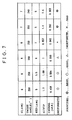
- FIG. 7 is an explanatory diagram of this embodiment and a comparative example.
- This figure shows a list of conditions for each liquid crystal display panel used as a sample and the results of a sensor evaluation for uniformity.
- nematic liquid crystals of positive dielectric anisotropy were used for materials which exhibited an HTP (helical twist pitch) of 5, 5.5, 6, and 7 ⁇ m, respectively, when ester chiral nematic was added to each of the liquid crystal display panels.
- the refractive-index anisotropy ⁇ n was 0.14
- the cell thickness d was 6 or 7 ⁇ m
- ⁇ n d was 0.84
- the twist angle was 250° or 240°.
- Super video graphics arrays (SVGA) of 11.3 type were configured using the above conditions, and a drive waveform of 1/300 duty cycle, 1/18 bias, and 120 Hz frequency was added to these SVGA display panels to carry out a visual sensor evaluation for uniformity using a normally black configuration.
- the results of the evaluation are shown in the bottom of FIG. 7.
- this uniformity row when 0.393 wt% of chiral nematic was added, the best result was obtained when the HTP was 5 ⁇ m and when the cell thickness d was 7 ⁇ m.
- the twist angle both 250° and 240° are shown to contribute to good results, but the most preferable value was 240° or less.
- FIG. 1 shows the relationship between the change in the transition temperature from the nematic liquid crystal to the isotropic liquid and the amount of chiral agent added, in the liquid crystal panels evaluated according to this embodiment.
- the change in the transition temperature to the isotropic liquid refers to values obtained by comparing the transition temperature measured when no chiral agent is added with the transition temperature measured after a chiral agent has been added.
- the performance of the liquid crystal is degraded as the transition temperature decreases. Accordingly, the smaller the change in transition temperature is, the more excellent the liquid crystal display panel is, and in FIG. 1, the performance of the liquid crystal display panel increases with decreasing value of the transition temperature. Thus, the results indicate that the performance increases with decreasing amount of chiral agent added.
- FIG. 2 is a comparatory diagram describing the relationship between the voltage and HTP and cell thickness d at which the display becomes uniform during the application of a static waveform, in the liquid crystal display panels according to this embodiment.
- FIG. 1 indicates that the optimal conditions are an HTP of about 5 ⁇ m, a cell thickness d of 7 ⁇ m, and a twist angle of 240°.
- FIG. 3 compares the absolute transmittance with the amount of chiral agent added when the light transmittance becomes lowest during the application of a static waveform, in the liquid crystal display panels according to this embodiment.
- the absolute transmittance refers to the ratio of the amount of light transmitted through a liquid crystal display panel with its transmittance minimized to the amount of light present prior to the transmission. The smaller the absolute transmittance is, the more excellent and the clearer the panel is.
- FIG. 3 shows that the absolute transmittance decreases with decreasing amount of chiral agent added. In addition, better results are obtained when the cell thickness d and twist angle are 7 ⁇ m and 240°, respectively, than when they are 6 ⁇ m and 250°, respectively.
- FIG. 4 shows the relationship between the d/HTP and the change in the transition temperature from the nematic liquid crystal to the isotropic liquid, in the liquid crystal display panels evaluated according to this embodiment.
- the change in transition temperature is largest when the d/HTP is 1.1.
- FIG. 5 shows the relationship between the voltage and d/HTP at which the display becomes uniform during the application of a static waveform, in the liquid crystal display panels according to this embodiment.
- the cell thickness d was 6 ⁇ m
- the twist angle was 250°
- the display was uniform with no voltage applied.
- the d/HTP was 1.1 or more
- the change in voltage was zero and the display was uniform and provided excellent performance.
- the display was not uniform when the d/HTP was less than 1.1, so a voltage had to be applied to make the display uniform.
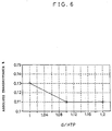
- FIG. 6 compares the absolute transmittance with the d/HTP when the transmittance becomes lowest during the application of a static waveform, in the liquid crystal display panels according to this embodiment.
- the absolute transmittance is as described in FIG. 3; the smaller the transmittance is, the less light is transmitted and the more excellent and the clearer the liquid crystal display panel is. Consequently, excellent liquid crystal display panels are obtained when the d/HTP is 1.1 or more.
- the uniformity and alignment stability can be obtained and the change in Tni can be reduced, thereby enabling the optical characteristics of the panel to be balanced.
- particularly high effects can be obtained by reducing the amount of chiral agent added down to 0.5 wt% or less and meeting the condition that (d/HTP) ⁇ 1.1 .
- the above embodiment improved alignment stability, display uniformity, and further display quality.
- a stable alignment margin could be obtained when the cell thickness d was 7 ⁇ m or more and when the twist angle was 240°. Under these conditions, the above effects can be further improved.
Landscapes
- Physics & Mathematics (AREA)
- Nonlinear Science (AREA)
- Chemical & Material Sciences (AREA)
- Crystallography & Structural Chemistry (AREA)
- General Physics & Mathematics (AREA)
- Optics & Photonics (AREA)
- Liquid Crystal (AREA)
- Mathematical Physics (AREA)
- Spectroscopy & Molecular Physics (AREA)
- Engineering & Computer Science (AREA)
- Materials Engineering (AREA)
- Organic Chemistry (AREA)
- Devices For Indicating Variable Information By Combining Individual Elements (AREA)
Applications Claiming Priority (3)
| Application Number | Priority Date | Filing Date | Title |
|---|---|---|---|
| JP9155623A JPH112793A (ja) | 1997-06-13 | 1997-06-13 | 液晶表示パネル |
| JP155623/97 | 1997-06-13 | ||
| JP15562397 | 1997-06-13 |
Publications (2)
| Publication Number | Publication Date |
|---|---|
| EP0884625A2 true EP0884625A2 (de) | 1998-12-16 |
| EP0884625A3 EP0884625A3 (de) | 1999-12-01 |
Family
ID=15610058
Family Applications (1)
| Application Number | Title | Priority Date | Filing Date |
|---|---|---|---|
| EP98110849A Withdrawn EP0884625A3 (de) | 1997-06-13 | 1998-06-12 | Flüssigkristall-Anzeigevorrichtung |
Country Status (6)
| Country | Link |
|---|---|
| US (1) | US6108069A (de) |
| EP (1) | EP0884625A3 (de) |
| JP (1) | JPH112793A (de) |
| KR (1) | KR19990006946A (de) |
| CN (1) | CN1107238C (de) |
| TW (1) | TW476855B (de) |
Cited By (1)
| Publication number | Priority date | Publication date | Assignee | Title |
|---|---|---|---|---|
| GB2366873A (en) * | 2000-04-14 | 2002-03-20 | Merck Patent Gmbh | Electro-optical liquid-crystal display |
Families Citing this family (3)
| Publication number | Priority date | Publication date | Assignee | Title |
|---|---|---|---|---|
| US7271863B2 (en) * | 2002-10-16 | 2007-09-18 | Nitto Denko Corporation | Color liquid crystal display with internal rear polarizer |
| JP2005010202A (ja) * | 2003-06-16 | 2005-01-13 | Nec Corp | 液晶パネル、該液晶パネルを用いた液晶表示装置および該液晶表示装置を搭載した電子機器 |
| JP2007219413A (ja) * | 2006-02-20 | 2007-08-30 | Fujifilm Corp | 液晶調光デバイスの駆動方法及び液晶調光デバイス |
Family Cites Families (7)
| Publication number | Priority date | Publication date | Assignee | Title |
|---|---|---|---|---|
| FR2356173A1 (fr) * | 1976-06-21 | 1978-01-20 | Gen Electric | Procede pour ameliorer le temps de descente d'un dispositif d'affichage a composition de cristaux liquides nematique en helice |
| JPS54134452A (en) * | 1978-04-10 | 1979-10-18 | Hitachi Ltd | Quest-host type liquid crystal display device |
| JPS56156817A (en) * | 1980-05-09 | 1981-12-03 | Hitachi Ltd | Liquid-crystal display element |
| US4529271A (en) * | 1982-03-12 | 1985-07-16 | At&T Bell Laboratories | Matrix addressed bistable liquid crystal display |
| EP0231781B1 (de) * | 1986-01-22 | 1992-04-01 | Hitachi, Ltd. | Flüssigkristallanzeigeelement |
| NL8600284A (nl) * | 1986-02-06 | 1987-09-01 | Philips Nv | Vloeibaar kristalinrichting. |
| JPH08122829A (ja) * | 1994-10-27 | 1996-05-17 | Fujitsu Ltd | 液晶表示パネル |
-
1997
- 1997-06-13 JP JP9155623A patent/JPH112793A/ja active Pending
-
1998
- 1998-06-01 TW TW087108514A patent/TW476855B/zh not_active IP Right Cessation
- 1998-06-11 US US09/095,603 patent/US6108069A/en not_active Expired - Fee Related
- 1998-06-12 CN CN98114747A patent/CN1107238C/zh not_active Expired - Fee Related
- 1998-06-12 EP EP98110849A patent/EP0884625A3/de not_active Withdrawn
- 1998-06-12 KR KR1019980022043A patent/KR19990006946A/ko not_active Withdrawn
Cited By (3)
| Publication number | Priority date | Publication date | Assignee | Title |
|---|---|---|---|---|
| GB2366873A (en) * | 2000-04-14 | 2002-03-20 | Merck Patent Gmbh | Electro-optical liquid-crystal display |
| GB2366873B (en) * | 2000-04-14 | 2004-09-29 | Merck Patent Gmbh | Electro-optical liquid-crystal display |
| US6800338B2 (en) | 2000-04-14 | 2004-10-05 | Merck Patentgesellschaft | Electro-optical liquid-crystal display |
Also Published As
| Publication number | Publication date |
|---|---|
| KR19990006946A (ko) | 1999-01-25 |
| EP0884625A3 (de) | 1999-12-01 |
| CN1107238C (zh) | 2003-04-30 |
| JPH112793A (ja) | 1999-01-06 |
| US6108069A (en) | 2000-08-22 |
| TW476855B (en) | 2002-02-21 |
| CN1202632A (zh) | 1998-12-23 |
Similar Documents
| Publication | Publication Date | Title |
|---|---|---|
| JP2700006B2 (ja) | 液晶表示素子 | |
| JP5178831B2 (ja) | 液晶表示装置 | |
| EP0259822B2 (de) | Flüssigkristall-Anzeigevorrichtung | |
| US20050179632A1 (en) | Display element and display apparatus | |
| US5093741A (en) | Liquid crystal display device | |
| JP3342430B2 (ja) | 液晶素子及び液晶表示装置 | |
| JP4621788B2 (ja) | 液晶パネルおよび液晶表示装置 | |
| US8199299B2 (en) | Liquid crystal panel, liquid crystal display device, and display method of liquid crystal panel | |
| US6151093A (en) | Liquid crystal display device having mixture to suppress changing switching characteristics with temperature of the liquid crystal display device | |
| US7540975B2 (en) | Optically compensated birefringence alignment agent, liquid crystal display utilizing the same and fabrication method thereof | |
| US6781664B1 (en) | Liquid-crystal switching elements comprising a liquid-crystal layer which has extremely low optical retardation and liquid-crystal displays containing them | |
| JPH01280722A (ja) | 液晶表示装置 | |
| US6108069A (en) | Liquid crystal display panel | |
| EP1246158B1 (de) | Anzeigeeinheit zur Darstellung von bewegten Bildern | |
| CN102047175B (zh) | 液晶面板和液晶显示装置 | |
| KR100412125B1 (ko) | 액정 표시장치 | |
| KR19990027489A (ko) | 강유전성 액정을 첨가한 수직 배향 비틀린 네마틱 액정 표시 장치 | |
| Lee et al. | P‐93: High Performance 17.0 ″SVGA OCB Panel with Fast Initial Bend Transition | |
| CN114063337B (zh) | 外延取向液晶显示器 | |
| Oka et al. | Electro-optical properties of the in-plane switching twisted nematic mode | |
| Oka et al. | Viewing angle characteristics and cell gap tolerance of the in-plane switching twisted nematic mode | |
| Lee et al. | Multi‐Domainlike, Homeotropic Nematic Liquid Crystal Display | |
| JP2946713B2 (ja) | 液晶表示装置 | |
| JPS6310126A (ja) | 液晶表示装置 | |
| US20050116909A1 (en) | Video speed STN display |
Legal Events
| Date | Code | Title | Description |
|---|---|---|---|
| PUAI | Public reference made under article 153(3) epc to a published international application that has entered the european phase |
Free format text: ORIGINAL CODE: 0009012 |
|
| AK | Designated contracting states |
Kind code of ref document: A2 Designated state(s): DE FR GB |
|
| AX | Request for extension of the european patent |
Free format text: AL;LT;LV;MK;RO;SI |
|
| PUAL | Search report despatched |
Free format text: ORIGINAL CODE: 0009013 |
|
| AK | Designated contracting states |
Kind code of ref document: A3 Designated state(s): AT BE CH CY DE DK ES FI FR GB GR IE IT LI LU MC NL PT SE |
|
| AX | Request for extension of the european patent |
Free format text: AL;LT;LV;MK;RO;SI |
|
| 17P | Request for examination filed |
Effective date: 20000204 |
|
| AKX | Designation fees paid |
Free format text: DE FR GB |
|
| STAA | Information on the status of an ep patent application or granted ep patent |
Free format text: STATUS: THE APPLICATION IS DEEMED TO BE WITHDRAWN |
|
| 18D | Application deemed to be withdrawn |
Effective date: 20060516 |