Field of the Invention
The present invention relates to a liquid crystal display
panel used for a liquid crystal display apparatus which is one
of image displays.
Background of the Invention
Liquid crystal display apparatuses use a liquid crystal
panel that uses the optical characteristic of a liquid crystal
that changes its initial alignment orientation to another
alignment state. Since the liquid crystal display apparatus
can be driven by a lower voltage than conventional display
apparatuses, it is suitable to be driven by LSIs, consumes low
power, and allows its thickness and weight to be reduced. In
recent years, in line with the trend of increasing the size of
the screen and the capacity of the apparatus, the liquid
crystal display apparatuses have been developed and
commercialized so as to be mounted in OA or AV equipments.
Presently, depending on required features, relevant
products include liquid crystal display apparatuses that use
changes in the alignment state of the liquid crystal caused by
the application of electric fields, that is, STN (super
twisted nematic) liquid crystal display apparatuses based on a
simple matrix method and using the electrooptical
characteristic of the liquid crystal or TFT (thin film
transistor) liquid crystal display apparatuses based on an
active matrix method.
FIG. 8 shows a configuration drawing showing the basic
structure of a liquid crystal display panel used for such a
liquid crystal display apparatus. In this figure, 1 is a
segment-side glass substrate; 2 is a common-side glass
substrate; 3 is a sealing agent containing spacers; 4 is a
common-side ITO (indium tin oxide) electrode formed of a
transparent electrode film; 5 is a segment-side ITO electrode
formed of a transparent electrode film; 6 is a vertical black
matrix; 7 is an alignment layer; 8 is a spacer; 9 is a liquid
crystal; and 10 is a color filter.
In this manner, the liquid crystal display panel used for
the liquid crystal display apparatus has a sandwich structure
in which the liquid crystal is sandwiched between the two
glass substrates on which the transparent electrode pattern
film is formed. A polymeric thin film is formed on the
transparent electrode film to orient the liquid crystal. In
the STN liquid crystal display panel, the cell thickness d
between the substrates is normally 5 to 7 µm. In this liquid
crystal display panel, the polymeric thin film is rubbed to
control the alignment of the liquid crystal so as to provide a
pretilt angle of 3° to 8°. In addition, the STN method uses
the birefringence of the liquid crystal and the optical
rotatory of light and provides a significantly-steep-threshold
characteristic by twisting the alignment direction of the
liquid crystal between the two substrates through an angle of
180° to 270°. Thus, the cell thickness d requires an accuracy
equivalent to 0.05 to 0.1 µm according to the STN method.
In addition, since the liquid crystal molecules are
twisted through the above angle within the predetermined
thickness d, a trace amount of chiral agent is added to the
liquid crystal to induce a specified twisted liquid crystal
alignment. The trace amount of agent added depends on the
alignment layer and pretilt angle, liquid crystal materials,
the chiral agent, and the twist angle, and is normally 1 wt%.
The optical characteristics of the liquid crystal display
panel are obtained by the birefringence and dielectric
constant anisotropy Δε of the liquid crystal molecules.
These optical characteristics vary depending on the
composition of the liquid crystal materials including their
viscosities and elastic constants or the adjustment of the
composition ratio. Various liquid crystal materials are now
developed and mixed together to provide desired
characteristics.
Δε is set depending on the balance among the threshold
voltage, drive waveform, cell thickness d, twist angle, and
other optical characteristics taking into consideration the
voltage resistance of LSIs that drive the liquid crystal
display panel. The characteristics of the liquid crystal
display panel are finally determined by the combination of Δn
× d, that is, the product of the birefringence of the liquid
crystal Δn and the thickness of the liquid crystal layer
(cell thickness) d and the optical compensation configuration
of an optical retardation film.
In the conventional liquid crystal display panel used for
the STN liquid crystal display panel, in order to twist the
nematic liquid crystal molecules sandwiched between the glass
substrates through a predetermined twist angle, a chiral
nematic liquid crystal or a cholesterol derivative is added as
a chiral agent to induce a twisted alignment. Although,
however, the chiral nematic liquid crystal is similar to the
nematic liquid crystal in molecular shape and chemical and
optical stability, the nature of the above chiral agent is
inherently different from that of the nematic liquid crystal
and causes various inconveniences in the liquid crystal
display panel.
Specifically, due to its asymmetric carbon atoms of a
high stereoscopic nature located at its molecular terminal
group, the chiral agent obstructs the order of the alignment
of the liquid crystal molecules in the liquid crystal bulk or
interface to degrade the uniformity of the micro display. It
also causes similar non-uniform display associated with the
alignment of the spacers used to maintain the cell thickness
d.
In addition, the addition of the chiral agent reduces the
temperature (Tni point) changing from the nematic liquid
crystal layer to an isotropic liquid to degrade the
temperature characteristic, thereby forcing the characteristic
balance (contrast and response speed) to be reduced to achieve
the same temperature characteristic.
This invention solves these problems and provides a
liquid crystal display panel that can improve alignment
stability, display uniformity, and display quality.
Disclosure of the Invention
To achieve this object, a liquid crystal display panel
according to this invention is characterized in that the panel
provides a uniform display by facilitating the stable
alignment of liquid crystal materials and inducing a twisted
alignment and in that it improves the balance among the
optical characteristics.
Claim 1 sets forth a liquid crystal display panel
comprising a liquid crystal sandwiched between two substrates
each of which has aligning treatment applied to a transparent
electrode pattern formed on one of its main surfaces, wherein
0.5 wt% or less of chiral agent is added to the liquid crystal
and wherein the HTP (helical twist pitch) and cell thickness d
meet the following relational expression when 1 wt% of chiral
agent is added: 1.1 × P ≦ d.
This configuration stabilizes the alignment in the liquid
crystal display panel to improve display uniformity and
improves the optical characteristics.
Claim 2 sets forth a liquid crystal display panel
according to Claim 1 wherein the cell thickness d is 7 µm or
more.
This configuration reduces the dependence on pitch
variations in alignment margin to provide a stable alignment
margin.
Claim 3 sets forth a liquid crystal display panel
according to Claim 1 or 2 wherein a twist angle through which
the molecules of the liquid crystal are twisted is 240° or
less.
This configuration provide a large alignment margin to
maintain a stable alignment state against variations in d or
P.
As described above, the liquid crystal display panel
according to this invention facilitates the stable alignment
of liquid crystal materials and induces a twisted alignment to
provide a uniform display and to improve the balance among the
optical characteristics.
Brief Description of the Drawings
FIG. 1 shows the relationship between the change in the
transition temperature from a nematic liquid crystal to an
isotropic liquid and the amount of chiral agent added, which
was evaluated using a liquid crystal display panel according
to an embodiment of this invention;
FIG. 2 compares voltages at which the display becomes
uniform during the application of a static waveform according
to the same embodiment wherein the voltage is zero under the
following conditions: cell thickness d: 7 µm; HTP: 5 µm; and
twist angle: 240°;
FIG. 3 compares the absolute transmittance with the
amount of chiral agent added when the transmittance becomes
lowest during the application of a static waveform according
to the same embodiment;
FIG. 4 shows the relationship between the d/HTP and the
change in the transition temperature from the nematic liquid
crystal to the isotropic liquid, which was evaluated according
to the same embodiment;
FIG. 5 compares voltages at which the display becomes
uniform during the application of a static waveform according
to the same embodiment wherein the voltage is zero under the
following conditions: cell thickness d: 6 µm; HTP: 5 µm; and
twist angle: 250°;
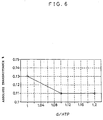
FIG. 6 compares the absolute transmittance with the d/HTP
when the transmittance becomes lowest during the application
of a static waveform according to the same embodiment;
FIG. 7 is an explanatory diagram of a basic form of a
liquid crystal display panel according to the same embodiment;
and
FIG. 8 is a drawing of the basic structure of the liquid
crystal display panel according to the same embodiment.
Description of the Embodiments
A liquid crystal display panel indicating an embodiment
of this invention is specifically described with reference to
the drawings. Although the liquid crystal display panel
configured as shown in FIG. 8 is also described in this
section, its basic structure has already been described in
"Prior Art" so its description is omitted.
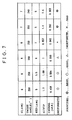
FIG. 7 is an explanatory diagram of this embodiment and a
comparative example. This figure shows a list of conditions
for each liquid crystal display panel used as a sample and the
results of a sensor evaluation for uniformity. As shown in
this figure, nematic liquid crystals of positive dielectric
anisotropy were used for materials which exhibited an HTP
(helical twist pitch) of 5, 5.5, 6, and 7 µm, respectively,
when ester chiral nematic was added to each of the liquid
crystal display panels. The refractive-index anisotropy Δn
was 0.14, the cell thickness d was 6 or 7 µm, Δn
d was
0.84, and the twist angle was 250° or 240°.
Super video graphics arrays (SVGA) of 11.3 type were
configured using the above conditions, and a drive waveform of
1/300 duty cycle, 1/18 bias, and 120 Hz frequency was added to
these SVGA display panels to carry out a visual sensor
evaluation for uniformity using a normally black
configuration. The results of the evaluation are shown in the
bottom of FIG. 7. As shown in this uniformity row, when 0.393
wt% of chiral nematic was added, the best result was obtained
when the HTP was 5 µm and when the cell thickness d was 7 µm.
For the twist angle, both 250° and 240° are shown to contribute
to good results, but the most preferable value was 240° or
less.
When 0.642 wt% of chiral nematic was added, the
uniformity was unacceptable when the HTP was 7 µm and when the
cell thickness d was 6 µm. When 0.458 or 0.504 wt% of chiral
nematic was added, the uniformity was acceptable when the HTP
was 5 or 5.5 µm and when the cell thickness d was 6 µm.
A 64 Hz static drive waveform was applied to these SVGA
display panels to compare voltages at which micro uniformity
was established visually, and it was also determined how the
transition temperature (Tni) from the nematic liquid crystal
to an isotropic liquid changed after the addition of the
chiral agent. The results of the measurements are shown in
FIGS. 1 to 6.
FIG. 1 shows the relationship between the change in the
transition temperature from the nematic liquid crystal to the
isotropic liquid and the amount of chiral agent added, in the
liquid crystal panels evaluated according to this embodiment.
The change in the transition temperature to the isotropic
liquid refers to values obtained by comparing the transition
temperature measured when no chiral agent is added with the
transition temperature measured after a chiral agent has been
added. The performance of the liquid crystal is degraded as
the transition temperature decreases. Accordingly, the
smaller the change in transition temperature is, the more
excellent the liquid crystal display panel is, and in FIG. 1,
the performance of the liquid crystal display panel increases
with decreasing value of the transition temperature. Thus,
the results indicate that the performance increases with
decreasing amount of chiral agent added. In the figure, "d =
6" indicates a cell thickness of 6 µm, and "250° twist"
indicates that a liquid crystal of twist angle 250° was used.
"+" indicates a liquid crystal display panel using a liquid
crystal of cell thickness 7 µm and twist angle 250°, while "⋄"
indicates a liquid crystal display panel using a liquid
crystal of cell thickness 7 µm and twist angle 240°.
FIG. 2 is a comparatory diagram describing the
relationship between the voltage and HTP and cell thickness d
at which the display becomes uniform during the application of
a static waveform, in the liquid crystal display panels
according to this embodiment.
Under the condition "⋄" (the cell thickness d was 7 µm,
the HTP was 5 µm, and the twist angle was 240°), the voltage
was zero because the display was uniform, thereby eliminating
the need to apply a voltage. Under the condition "+", the
display was not uniform so 0.01 V of voltage had to be applied
relative to the condition "⋄". Under the condition "□",
0.03 V of voltage was applied relative to the condition "⋄" in
order to make the display uniform. FIG. 1 indicates that the
optimal conditions are an HTP of about 5 µm, a cell thickness
d of 7 µm, and a twist angle of 240°.
FIG. 3 compares the absolute transmittance with the
amount of chiral agent added when the light transmittance
becomes lowest during the application of a static waveform, in
the liquid crystal display panels according to this
embodiment. The absolute transmittance refers to the ratio of
the amount of light transmitted through a liquid crystal
display panel with its transmittance minimized to the amount
of light present prior to the transmission. The smaller the
absolute transmittance is, the more excellent and the clearer
the panel is. FIG. 3 shows that the absolute transmittance
decreases with decreasing amount of chiral agent added. In
addition, better results are obtained when the cell thickness
d and twist angle are 7 µm and 240°, respectively, than when
they are 6 µm and 250°, respectively.
FIG. 4 shows the relationship between the d/HTP and the
change in the transition temperature from the nematic liquid
crystal to the isotropic liquid, in the liquid crystal display
panels evaluated according to this embodiment. The change in
transition temperature is largest when the d/HTP is 1.1.
FIG. 5 shows the relationship between the voltage and
d/HTP at which the display becomes uniform during the
application of a static waveform, in the liquid crystal
display panels according to this embodiment. When the cell
thickness d was 6 µm, the HTP was 5 µm (d/HTP = 1.2), and the
twist angle was 250°, the display was uniform with no voltage
applied. As is apparent from this figure, when the d/HTP was
1.1 or more, the change in voltage was zero and the display
was uniform and provided excellent performance. The display,
however, was not uniform when the d/HTP was less than 1.1, so
a voltage had to be applied to make the display uniform.
FIG. 6 compares the absolute transmittance with the d/HTP
when the transmittance becomes lowest during the application
of a static waveform, in the liquid crystal display panels
according to this embodiment. The absolute transmittance is
as described in FIG. 3; the smaller the transmittance is, the
less light is transmitted and the more excellent and the
clearer the liquid crystal display panel is. Consequently,
excellent liquid crystal display panels are obtained when the
d/HTP is 1.1 or more.
(Result 1)
As shown in FIG. 7, by reducing the amount of chiral
agent added, the uniformity and alignment stability can be
obtained and the change in Tni can be reduced, thereby
enabling the optical characteristics of the panel to be
balanced. In this case, particularly high effects can be
obtained by reducing the amount of chiral agent added down to
0.5 wt% or less and meeting the condition that (d/HTP) ≧ 1.1.
(Result 2)
Using the same Δn
d, alignment margin, and HTP (5 µm)
for the liquid crystals with only the Δn adjusted and using a
cell thickness d of 7 µm and a twist angle of 240°, an
evaluation similar to that in
Result 1 was executed. The
results indicate that the alignment margin increases and thus
uniformity is enhanced with increasing cell thickness d and
decreasing twist angle. In addition, the effects can be
improved by meeting the condition that
(d/HTP) ≧ 1.1.
Thus, the above embodiment improved alignment stability,
display uniformity, and further display quality. In
particular, a stable alignment margin could be obtained when
the cell thickness d was 7 µm or more and when the twist angle
was 240°. Under these conditions, the above effects can be
further improved.
Although the above embodiment uses the ester chiral
nematic liquid crystal as a chiral agent, similar effects have
been confirmed using several other chiral agents such as
biphenyl.