EP0884200B1 - Bandage pneumatiques radiaux pour poids-lourds - Google Patents
Bandage pneumatiques radiaux pour poids-lourds Download PDFInfo
- Publication number
- EP0884200B1 EP0884200B1 EP98304546A EP98304546A EP0884200B1 EP 0884200 B1 EP0884200 B1 EP 0884200B1 EP 98304546 A EP98304546 A EP 98304546A EP 98304546 A EP98304546 A EP 98304546A EP 0884200 B1 EP0884200 B1 EP 0884200B1
- Authority
- EP
- European Patent Office
- Prior art keywords
- tire
- bead
- reinforcing layer
- bead portion
- steel cord
- Prior art date
- Legal status (The legal status is an assumption and is not a legal conclusion. Google has not performed a legal analysis and makes no representation as to the accuracy of the status listed.)
- Expired - Lifetime
Links
Images


Classifications
-
- B—PERFORMING OPERATIONS; TRANSPORTING
- B60—VEHICLES IN GENERAL
- B60C—VEHICLE TYRES; TYRE INFLATION; TYRE CHANGING; CONNECTING VALVES TO INFLATABLE ELASTIC BODIES IN GENERAL; DEVICES OR ARRANGEMENTS RELATED TO TYRES
- B60C9/00—Reinforcements or ply arrangement of pneumatic tyres
- B60C9/02—Carcasses
- B60C9/04—Carcasses the reinforcing cords of each carcass ply arranged in a substantially parallel relationship
- B60C9/08—Carcasses the reinforcing cords of each carcass ply arranged in a substantially parallel relationship the cords extend transversely from bead to bead, i.e. radial ply
-
- B—PERFORMING OPERATIONS; TRANSPORTING
- B60—VEHICLES IN GENERAL
- B60C—VEHICLE TYRES; TYRE INFLATION; TYRE CHANGING; CONNECTING VALVES TO INFLATABLE ELASTIC BODIES IN GENERAL; DEVICES OR ARRANGEMENTS RELATED TO TYRES
- B60C15/00—Tyre beads, e.g. ply turn-up or overlap
- B60C15/06—Flipper strips, fillers, or chafing strips and reinforcing layers for the construction of the bead
-
- B—PERFORMING OPERATIONS; TRANSPORTING
- B60—VEHICLES IN GENERAL
- B60C—VEHICLE TYRES; TYRE INFLATION; TYRE CHANGING; CONNECTING VALVES TO INFLATABLE ELASTIC BODIES IN GENERAL; DEVICES OR ARRANGEMENTS RELATED TO TYRES
- B60C9/00—Reinforcements or ply arrangement of pneumatic tyres
- B60C9/0007—Reinforcements made of metallic elements, e.g. cords, yarns, filaments or fibres made from metal
- B60C2009/0021—Coating rubbers for steel cords
-
- Y—GENERAL TAGGING OF NEW TECHNOLOGICAL DEVELOPMENTS; GENERAL TAGGING OF CROSS-SECTIONAL TECHNOLOGIES SPANNING OVER SEVERAL SECTIONS OF THE IPC; TECHNICAL SUBJECTS COVERED BY FORMER USPC CROSS-REFERENCE ART COLLECTIONS [XRACs] AND DIGESTS
- Y10—TECHNICAL SUBJECTS COVERED BY FORMER USPC
- Y10T—TECHNICAL SUBJECTS COVERED BY FORMER US CLASSIFICATION
- Y10T152/00—Resilient tires and wheels
- Y10T152/10—Tires, resilient
- Y10T152/10495—Pneumatic tire or inner tube
- Y10T152/10819—Characterized by the structure of the bead portion of the tire
- Y10T152/10828—Chafer or sealing strips
-
- Y—GENERAL TAGGING OF NEW TECHNOLOGICAL DEVELOPMENTS; GENERAL TAGGING OF CROSS-SECTIONAL TECHNOLOGIES SPANNING OVER SEVERAL SECTIONS OF THE IPC; TECHNICAL SUBJECTS COVERED BY FORMER USPC CROSS-REFERENCE ART COLLECTIONS [XRACs] AND DIGESTS
- Y10—TECHNICAL SUBJECTS COVERED BY FORMER USPC
- Y10T—TECHNICAL SUBJECTS COVERED BY FORMER US CLASSIFICATION
- Y10T152/00—Resilient tires and wheels
- Y10T152/10—Tires, resilient
- Y10T152/10495—Pneumatic tire or inner tube
- Y10T152/10819—Characterized by the structure of the bead portion of the tire
- Y10T152/10837—Bead characterized by the radial extent of apex, flipper or chafer into tire sidewall
-
- Y—GENERAL TAGGING OF NEW TECHNOLOGICAL DEVELOPMENTS; GENERAL TAGGING OF CROSS-SECTIONAL TECHNOLOGIES SPANNING OVER SEVERAL SECTIONS OF THE IPC; TECHNICAL SUBJECTS COVERED BY FORMER USPC CROSS-REFERENCE ART COLLECTIONS [XRACs] AND DIGESTS
- Y10—TECHNICAL SUBJECTS COVERED BY FORMER USPC
- Y10T—TECHNICAL SUBJECTS COVERED BY FORMER US CLASSIFICATION
- Y10T152/00—Resilient tires and wheels
- Y10T152/10—Tires, resilient
- Y10T152/10495—Pneumatic tire or inner tube
- Y10T152/10819—Characterized by the structure of the bead portion of the tire
- Y10T152/10846—Bead characterized by the chemical composition and or physical properties of elastomers or the like
-
- Y—GENERAL TAGGING OF NEW TECHNOLOGICAL DEVELOPMENTS; GENERAL TAGGING OF CROSS-SECTIONAL TECHNOLOGIES SPANNING OVER SEVERAL SECTIONS OF THE IPC; TECHNICAL SUBJECTS COVERED BY FORMER USPC CROSS-REFERENCE ART COLLECTIONS [XRACs] AND DIGESTS
- Y10—TECHNICAL SUBJECTS COVERED BY FORMER USPC
- Y10T—TECHNICAL SUBJECTS COVERED BY FORMER US CLASSIFICATION
- Y10T152/00—Resilient tires and wheels
- Y10T152/10—Tires, resilient
- Y10T152/10495—Pneumatic tire or inner tube
- Y10T152/10855—Characterized by the carcass, carcass material, or physical arrangement of the carcass materials
- Y10T152/10864—Sidewall stiffening or reinforcing means other than main carcass plies or foldups thereof about beads
Definitions
- This invention relates to a heavy duty pneumatic radial tire, and more particularly to a heavy duty pneumatic tire for use on heavy vehicles such as trucks, buses and the like capable of sufficiently developing excellent bead portion durability without additionally arranging extra reinforcing members in a bead portion for reducing the weight of the bead portion.
- a large number of these countermeasures lie in the use of many bead portion reinforcing cord layers or the increase of volume in the bead portion as a whole for reducing falling-down of a bead portion connected to a ground contact region toward the outside of the tire during the running under a load as far as possible to reduce strain acting to an end of a bead portion reinforcing cord layer or a turnup end of a carcass, and hence they involve increase of tire weight and increased cost.
- they are not appropriate to current demands such as weight reduction, cost reduction and the like.
- JP-B-1-26884 is disclosed a heavy duty pneumatic radial tire wherein a single metal cord reinforcing layer is disposed outside the turnup portion of the radial carcass ply and a cord arranging angle in an upper end portion of the reinforcing layer is not more than 20° with respect to the circumferential direction of the tire and a cord arranging angle in a region ranging from a start point of contacting with a flange of a rim toward a bead base is made larger by not less than 10° than the above angle at the upper end portion as a bead portion structure capable of maintaining and improving the durability even when the weight is reduced by decreasing the stiffener rubber likewise the above case.
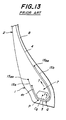
- a metal cord layer as a reinforcing layer for a bead portion 1 is divided at inside and outside of a bead core 3 into an outer metal cord layer (protection layer for end of turnup portion 4t) 15a and an inner metal cord layer (support reinforcing layer) 15b, respectively, noticing "settling" of the bead core in addition to falling-down of the bead portion.
- modulus at 1% elongation of the layer 15a is made smaller than that of the layer 15b and an inclination cord angle of each layer with respect to the radial plane of the tire on a circumference passing an upper end of the layer is within a range of 45-70° at maximum (20-45° with respect to the circumference of the tire), whereby the improvement of the bead portion durability is attained.
- the bead portion reinforcing layer is divided into the protection layer 15a for turnup 4t end and the support reinforcing layer 15 b (division ends P, Q of the layers 15a, 15b), the restraint by the ends 15ae, 15be of the layers at positions contacting with a rim is considerably moderate as compared with a case of using a single layer, and the layers 15a, 15b easily follow the remarkable shearing deformation in the circumferential direction of the tire at both stepping-in and kicking-out sides of the tread during the running of the tire under loading, and hence the concentration of strain acting to an outer end portion of each layer in the radial direction of the tire is largely mitigated.
- reference numeral 2 indicates a sidewall portion
- reference numeral 7 indicates a stuffener rubber.
- the tension T is a force of drawing out the carcass ply 4 from the bead core 3 in a direction shown by the arrow.
- the carcass ply 4 acts to largely rotate the bead core 3 around a graphic center of gravity Cg at a section of the bead core in a direction shown by an arrow r together with the force T and the moving easiness of the metal cord layers 15a, 15b.
- This action is applied to the bead core 3 every one rotation of the tire and the temperature of the bead portion 1 becomes high during the running of the vehicle, so that "settling" deformation as a plastic deformation is caused in the bead core 3 and the deformation degree proceeds as the running distance of the tire becomes long.
- Such a large "settling" deformation of the bead core 3 largely changes the sectional shape of the bead portion 1 from a new tire state.
- the deformation of the bead portion brings about a disadvantage that the bead portion reinforcing metal cord layer 15a located outside the turnup portion 4t of the carcass ply largely diverts from an arrangement of previously minimizing strain acting to the outer end portion of the layer in the radial direction of the tire and hence a large strain is concentrated in the vicinity of the outer end 15ae of the metal cord layer 15a and separation failure is apt to be caused in this end portion.
- an object of the invention to provide a heavy duty pneumatic radial tire having a light weight and a bead portion durability equal to or more than that of the conventional heavy duty pneumatic radial tire even when the winding number of steel wires in the bead core is decreased and the volume of rubber in the bead portion, particularly stiffener rubber is decreased accompanied therewith irrespective of being a tube-containing tire or tubeless tire.
- the tires according to the invention each comprise a pair of sidewall portions connecting to a pair of bead portions, a tread portion extending between both the sidewall portions, a belt reinforcing the tread portion on an outer periphery of the carcass and comprised of two or more cross cord layers, preferably two or more two cross steel cord layers according to custom.
- the carcass is one ply, it is preferable to use a rubberized steel cord.
- the cords of the carcass ply are arranged perpendicular or substantially perpendicular to an equatorial plane of the tire in the tread portion.
- inclination angle with respect to circumferential line of the tire means an angle defined between tangents of circumferential line and steel cord axial line at an assumption intersect of circumferential line at a given position (assumption line) and the cord axial line.
- a heavy duty pneumatic radial tire comprising a carcass of one or more rubberized cord plies extending between a pair of bead cores each embedded in a bead portion and containing cords arranged along a plane inclusive of a rotating axial center of the tire, at least one of which plies being wound around the bead core from the inside of the tire toward the outside thereof to form a turnup portion, and a bead portion reinforcing layer comprised of separately independent rubberized steel cord layer segments covering the carcass ply inclusive of its turnup portion in the bead portion, in which said bead portion reinforcing layer is comprised of two independent rubberized steel cord layer segments arranged at outside and inside regions of the bead portion with the bead core therebetween, and the outer end of the outer independent rubberized steel cord layer segment located at the outside region of the bead portion in the radial direction of the tire extends upward beyond the end of the turnup portion of the carcass p
- the term "vicinity" in the vicinity of the bead core means a partial gathering of all points wherein a distance from an arbitrary point I is smaller than a certain value in metric space, while the term “arbitrary point I” means all points existing on the bead core at section thereof. Also, the term “certain value of the distance from the point I” means a value that a distance measured from a point on a surface of the bead core in all directions is within a range of 0.5-20 mm. Furthermore, the term “adjoin each other” used herein includes a case of slightly separating away the opposed ends from each other in addition to a case of contacting the opposed ends with each other.
- the opposed ends of the two rubberized steel cord layer segments as the bead portion reinforcing layer are butted to each other.
- the butting position between the opposed ends is preferably existent around the bead core.
- the steel cords of the two layer segments located at the outside and inside regions of the bead portion are arranged in the same inclining direction with respect to a radius line of the tire.
- the steel cords of the two layer segments are arranged in an inclining direction opposite to each other with respect to a radius line of the tire.
- the adjoining position between the opposed ends of the two rubberized steel cord layer segments as the bead portion reinforcing layer is existent between a straight line passing through a graphic center of gravity in the bead core at section thereof and perpendicular to the rotating axis of the tire and a normal line drawn from an outermost end of a surface of the bead portion contacting with a flange of a rim in the radial direction of the tire to the carcass ply facing the inside of the tire.
- This type of tire is a radial ply tire for trucks and buses, in which a tire using the 15° drop center rim is a tubeless tire and a tire using the wide-width flat base rim as an approved rim is a tube-containing tire.
- the term "outermost end in the radial direction of the tire” used herein means a position when the tire is assembled onto the approved rim and inflated under a maximum air pressure corresponding to a maximum load capacity of the tire defined in "air pressure-load capacity table" according to the above standard.
- a heavy duty pneumatic radial tire comprising a carcass of one or more rubberized cord plies extending between a pair of bead cores each embedded in a bead portion and containing cords arranged along a plane inclusive of a rotating axial center of the tire, at least one of which plies being wound around the bead core from the inside of the tire toward the outside thereof to form a turnup portion, and a bead portion reinforcing layer comprised of separately independent rubberized steel cord layer segments covering the carcass ply inclusive of its turnup portion in the bead portion, in which said bead portion reinforcing layer comprises an inner reinforcing layer segment arranged at the inside region side of the carcass ply facing the inside of the tire, and an outer reinforcing layer segment arranged at the outside region side of the turnup portion of the carcass ply, the outer end of the outer reinforcing layer segment in the radial direction of the tire extends beyond the
- the steel cords in at least two layer segments among the three reinforcing layer segments as the bead portion reinforcing layer are arranged in the same inclining direction with respect to a radius line of the tire.
- a group of arranging two or more steel cords side by side is used as a steel cord in at least one layer segment among the (preferably three) reinforcing layer segments as the bead portion reinforcing layer.
- a coating rubber for steel cords in a layer segment arranged in at least the outer region of the bead portion has 100% modulus smaller than that of a coating rubber for cords in the carcass ply.
- At least one organic fiber cord layer is arranged so as to cover an outer surface of the bead portion reinforcing layer when at least one of load and running speed as a service condition is severe.
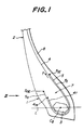
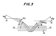
- Figs. 1 and 2 are diagrammatic left-half radial sections of two embodiments of a main part of a tubeless heavy duty pneumatic radial tire which is however not according to the present invention, respectively, and Fig. 3 is a schematic view illustrating arrangements of cords in the bead portion reinforcing layer and steel wires in the bead core opened-up from an arrow III shown in Fig. 1.
- a pair of bead portions 1 are connected to a pair of sidewall portions 2 and also a tread portion (not shown) extends between outer ends of the sidewall portions 2 in a radial direction of the tire.
- a carcass 4 is at least one rubberized cord ply (one ply in the illustrated embodiment) toroidally extending between a pair of bead cores 3 embedded in the bead portions 1 and containing, for example, steel cord arranged along a plane inclusive of a rotating axial center of the tire, which is wound around the bead core from the inside of the tire toward the outside thereof to form a turnup portion 4t.
- the bead portion 1 is provided with a bead portion reinforcing layer 5 comprised of a single rubberized steel cord layer (hereinafter referred to as a wire chafer).
- the wire chafer 5 extends from an outer position upward beyond an upper end 4te of the turnup portion 4t in the radial direction along an outer surface of the turnup portion 4t around the bead core 3 up to an inside region of the tire of a position beyond at least a maximum outer diameter of the bead core 3 so as to cover an outer surface of the carcass ply 4.
- a wire chafer 5 extends from an outer position upward beyond an upper end 4te of the turnup portion 4t in the radial direction along an outer surface of the turnup portion 4t around the bead core 3 up to an inside region of the tire of a position beyond at least a maximum outer diameter of the bead core 3 so as to cover an outer surface of the carcass ply 4.
- one or more organic fiber cord layers 6 (one layer in the illustrated embodiment), for example a nylon cord layer (hereinafter referred to as a nylon chafer) is further disposed along an outer surface of the wire chafer 5.
- a nylon cord layer hereinafter referred to as a nylon chafer
- each of the tires shown in Figs. 1 and 2 is provided with a stiffener rubber 7 and an innerliner 8 made from an air-impermeable rubber.
- the wire chafer 5 is divided into an outer portion 5 O and an inner portion 5 I .
- an inclination angle ⁇ OE of the cord 5C O in the vicinity of an end 5 OE of the outer portion 5 O with respect to a circumferential line Dt of the tire and an inclination angle ⁇ IE of the cord 5C I in the vicinity of an end 5 IE of the inner portion 5 I with respect to a circumferential line Dt of the tire are within a range of 22-35°, respectively.
- ⁇ I ( ⁇ IE + 5°) ⁇ ( ⁇ IE + 30°).
- the bead core 3 has a hexagonal shape in section formed by helically winding a steel wire 3w (see Fig. 3, circular section) covered with a coating rubber of a very thin gauge at an uncured stage in a given winding number (so-called hexagonal bead core).
- a so-called rectangular bead core formed by repeatedly winding and laminating a steel wire 3w having a rectangular shape at section or a bead core formed by repeatedly winding and laminating a steel wire 3w having a hexagonal shape at section may be used as the bead core 3.
- the carcass 4 inflated under a given air pressure causes a force for rotating the bead core 3 (rotational moment around the graphic center of gravity Cg) based on the above pulling-out force, whereby the bead core 3 is intended to rotate around the graphic center of gravity Cg.
- tension of the carcass 4 in the bead portion 1 becomes larger and hence the rotating force to the bead core 3 is further increased.
- the sectional shape at a new stage of the bead core as a gathering body of steel wires can not be maintained due to temperature rise through a great amount of heat generation in the bead portion during the running of the tire under loading and hence a large deformation is caused in the bead core. Since this deformation is irreversible, the bead core shows a large "settling" state and the shape of the bead portion as a whole is deformed accompanied therewith, which produces a large strain in an outer end portion of the wire chafer during the running of the tire under loading and finally causes a separation failure. In other words, the large plastic deformation of the bead core frequently brings about the occurrence of separation failure.
- the number of steel wires constituting the bead core is increased or a thick-diameter steel wire is used to make large the sectional shape of the bead core in the conventional tire, whereby torsional rigidity around the graphic center of gravity (Cg in Figs. 1 and 2) required for the deformation control is given to the bead core. In this case, however, it is obliged to increase the tire weight and the cost.
- positions of crossing the cords of the carcass 4 with the steel cords 5C O , 5C I of the wire chafer 5 around the bead core 3 can be increased to diminish the pulling-out force acting to the carcass 4 in the direction of arrow T under the inflation of a given air pressure.
- the rotation of the bead core 3 around the graphic center of gravity Cg can be controlled by the synergistic action of both the above features.
- the quantity of plastic deformation of the bead core 3 during the running of the tire under loading can largely be decreased, so that the deformation of the shape in the bead portion is very slight even when the wire amount of the bead core 3 is decreased. Therefore, strain in the vicinity of the end 5 OE of the wire chafer 5 can be decreased during the running of the tire under loading even with the reduction of the tire weight to improve the resistance to separation failure.
- the upper limit of the inclination angle difference ( ⁇ O - ⁇ OE ), ( ⁇ I - ⁇ IE ) may be 30°.
- the tire of Fig. 2 further added with the nylon chafer 6 is adaptable to a case of further improving the bead portion durability under a use condition of a larger load or under a condition of requiring recapping many times.
- a ratio of 100% modulus M 100W (kgf/cm 2 ) of a coating rubber for cords of the wire chafer 5 to 100% modulus M 100C (kgf/cm 2 ) of a coating rubber for cords of the carcass ply 4 is within a range of 0.6-1.0 in the case of considering the tire productivity, and the ratio is preferably within a range of 0.6-0.9 in the case of more improving the tire performances.
- the wire chafer 5 it is useful to use so-called cord groups formed by arranging two or more steel cords side by side along the surface of the chafer.
- the crack grows along the axis of the cord for the present and hence a time of connecting the cracks to each other in the circumferential direction can considerably be delayed to largely prolong the running distance of the tire until the occurrence of separation failure.
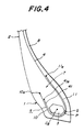
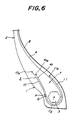
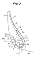
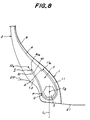
- FIG. 4 to 8 Various embodiments of the tire according to the first aspect of the invention are shown in Figs. 4 to 8, while two embodiments of the tire according to the second aspect of the invention are shown in Figs. 9 and 10, respectively.
- the same parts are represented by the same numerals and symbols as in the embodiments shown in Figs. 1 to 3.
- the bead portion 1 shown in Figs. 4-8 is provided with two independent rubberized steel cord layer segments 10, 11 as a bead portion reinforcing layer 5, while the bead portion 1 shown in Figs. 9-10 is provided with three independent rubberized steel cord layer segments 10, 11, 12 as a bead portion reinforcing layer 5.
- the two independent rubberized steel cord layer segments 10 and 11 are arranged at outside and inside regions of the bead portion 1 with the bead core 3 therebetween, in which the rubberized steel cord layer segment 10 mainly located at the side of the turnup portion 4t is called an outer reinforcing layer and the rubberized steel cord layer segment 11 mainly located at the side of the carcass ply 4 facing the inside of the tire is called an inner reinforcing layer.
- the rubberized steel cord layer segment 10 mainly located at the side of the turnup portion 4t is called an outer reinforcing layer
- the rubberized steel cord layer segment 11 mainly located at the side of the carcass ply 4 facing the inside of the tire is called an inner reinforcing layer.
- the three rubberized steel cord layer segments 10, 11 and 12 are arranged in the bead portion 1 inclusive of the bead core 3, in which the rubberized steel cord layer segment 10 located outside the turnup portion 4t is called an outer reinforcing layer, and the rubberized steel cord layer segment 11 located inside the carcass ply 4 facing the inside of the tire is called an inner reinforcing layer, and the rubberized steel cord layer segment 12 located around the bead core 3 is called a middle reinforcing layer.
- the outer reinforcing layer 10, the inner reinforcing layer 11 and further the middle reinforcing layer 12 are independent, they are arranged so as to adjoin each other as it they are a single continuous layer from the inside of the carcass ply 4 in the tire through the outside of the bead core 3 toward the outside of the turnup portion 4t.
- the outer reinforcing layer 10 located at the outside region of the bead portion 1 extends outward beyond an end 4te of the turnup portion 4t along the turnup portion of the carcass ply 4 in the radial direction of the tire.
- the opposed ends of the outer and inner reinforcing layers 10, 11 shown in Figs. 4-8, and the opposed ends of the outer, inner and middle reinforcing layers 10, 11, 12 shown in Figs. 9-10 are arranged in the vicinity of the bead core 3 so as to adjoin each other.
- an end P of the outer reinforcing layer 10 is adjoined to an end Q of the inner reinforcing layer 11.
- Such an adjoining relation of the opposed ends means butting these opposed ends to each other and slightly separating these opposed ends from each other.
- the case of slightly separating the opposed ends from each other is shown in all of Figs. 4-10.
- the adjoining position of the opposed ends P, Q is located at an inside of the tire around the bead core in Fig. 4, at an outside of the tire around the bead core in Fig. 5, at an outside of the tire in the vicinity of the bead core in Fig. 6, at an outside of the tire around the bead core in Fig. 7, and at an outside of the tire around the bead core in Fig. 8, respectively.
- the steel cords of the outer and inner reinforcing layers 10, 11 located at the outside and inside regions of the bead portion 1 and arranged in the vicinity of the outer ends 10e, 11e in the radial direction (outer end portion) have an inclination angle of 15-30° with respect to the circumferential line of the tire, while the steel cords arranged in the vicinity of the inner end of at least one of the outer and inner reinforcing layers 10, 11 in the radial direction or in at least one of the opposed ends P, Q thereof (inner end portion) have an inclination angle of 35-60° with respect to the circumferential line of the tire.
- the inclination angle of the steel cord arranged in the same layer is minimum at the outer end portion in the radial direction, and increases toward the opposed ends and is maximum at the vicinity of the opposed ends.
- the term "circumferential line of the tire” used herein means a circumferential line passing through a position specifying the inclination angle.
- Such a distribution of the inclination angle in the steel cord can be obtained by subjecting both surfaces of uncured materials as the outer and inner reinforcing layers 10, 11 to a given quantity of a forcedly deforming work prior to the building-up of an uncured tire.
- a case of giving the difference of inclination angle to the steel cords arranged in at least one of the reinforcing layers 10, 11 by taking account of the tire productivity and a case of giving the difference of inclination angle to both the reinforcing layers 10, 11 by taking account of the severity of use conditions.
- the inclination angle of the steel cord arranged in the vicinity of outer end 10e, 11e or in the vicinity of opposed ends P, Q with respect to the circumferential line of the tire is defined by an acute angle among angles between tangent of the circumferential line and tangent of central axis of the cord at an intersect between the central axis of the cord and the circumferential line of the tire.
- the reinforcing layer portion around the bead core 3 can develop a large resisting force to the rotation r of the bead core 3 around the graphic center of gravity Cg at section (see Fig. 13) due to the pulling-out tension T acting to the carcass ply 4.
- This resisting force develops an effect of preventing or largely mitigating the "settling" phenomenon of the bead core 3 inevitably produced in the bead portion together with the advance of the running distance in the conventional tire.
- a large plastic deformation of the bead portion 1 produced at the middle to last running stage of the tire is suppressed by the prevention or large mitigation of the "settling" phenomenon, which is possible to decrease strain applied to the outer end 10e of the outer reinforcing layer 10 in the radial direction and hence largely improve the resistance to separation failure.
- the term "settling" means a phenomenon based on plastic deformation of an extremely thin coating rubber for steel wire required in the production of the bead core 3 having a hexagonal shape at section as a wound body of the steel wire as shown in the illustrated embodiment.
- the section of the bead core 3 may take various polygonal shapes in addition to the hexagonal shape.
- the opposed ends of the outer and inner reinforcing layers 10, 11 are adjoined each other, whereby the fixation and restraint of the outer and inner reinforcing layers 10, 11 are loosened at the inflation of a tire-wheel assembly under a given air pressure and during the running of the tire under loading to decrease strain applied to the vicinity of the outer ends 10e, 11e of the outer and inner reinforcing layers 10, 11 in the radial direction.
- This largely contributes to improve the bead portion durability. That is, these three actions together can realize the bead portion durability equal to or more than that of the conventional tire having a heavy weight even when the winding number of the steel wires in the bead core 3 is decreased and the amount of rubber for the bead portion, e.g. rubber of the stiffener 7 is decreased to form a light weight tire.
- Numeral 8 is an innerliner, which is made from an air-impermeable rubber in the case of the tubeless tire.
- the inclining directions of the steel cords in the outer and inner reinforcing layers 10, 11 may be the same as each other with respect to the radius line of the tire.
- strain applied to the outer ends 10e, 11e of these layers 10, 11 can be mitigated and hence the invention can be utilized more advantageously. This is adaptable to tires for use in, for example, trucks running over a long distance.
- the inclining directions of the steel cords in the outer and inner reinforcing layers 10, 11 may be opposite to each other with respect to the radius line of the tire.
- the rigidity of the bead portion 1 to the rotating direction of the tire is substantially the same and the indication of the rotating direction is useless. This is adaptable to tires for city buses having a high frequency of starting and stopping.
- Fig. 7 is sectionally shown a main part of a tire-wheel assembly when a tubeless tire for truck and bus is assembled onto a 15° drop center rim (shown by only an outer profile) 20 and inflated under a maximum air pressure
- Fig. 8 is sectionally shown a main part of a tire-wheel assembly when a tube-containing tire for truck and bus is assembled onto a wide-width flat base rim (shown by only an outer profile) 21 and inflated under a maximum air pressure.
- positions of the opposed ends P, Q of the outer and inner reinforcing layers 10, 11 may be as follows.
- the opposed ends P, Q of the outer and inner reinforcing layers 10, 11 are located in a zone sandwiched between a straight line L 1 passing through the graphic center of gravity Cg in section of the bead core 3 and perpendicular to the rotating axis of the tire (not shown) and a normal line L 2 drawn from an outermost end A of a surface of the bead portion 1 contacting with a flange 20F, 21F of the rim 20, 21 in the radial direction to the carcass ply 4 facing the inside of the tire.
- the opposed ends of the outer and inner reinforcing layers 10, 11 are largely widened and the middle reinforcing layer 12 is disposed in the widened region between the opposed ends.
- the steel cords arranged at the outer ends 10e, 11e of the outer and inner reinforcing layers 10, 11, which are located at the outside and inside of the bead portion 1 sandwiching the bead core 3 therebetween, have an inclination angle of 15-30° with respect to the circumferential line of the tire and the steel cords arranged at the inner ends P, R of the outer and inner reinforcing layers 10, 11 have an inclination angle of 35-60° with respect to the circumferential line of the tire, which are the same as in the embodiments of Figs.
- the steel cords arranged in the middle reinforcing layer 12 around the bead core 3 between the outer and inner reinforcing layers 10 and 11 have an inclination angle larger than the inclination angle of the steel cord in the above inner ends P, R (35-60°) but not more than 90°.
- the position relation and adjoining relation between the opposed ends P and Q and between the opposed ends R and S are the same as previously mentioned.
- the steel cords in at least two of the outer, inner and middle reinforcing layers 10, 11 and 12 may be arranged in the same inclining direction with respect to the radius line of the tire.
- the function, effect and application are the same as previously mentioned.
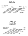
- the steel cords arranged in at least one of the outer, inner and middle reinforcing layers 10, 11, 12, desirably the outer reinforcing layer 10, have a cord group 10C (11C) of arranging two or more cords (two cords in the illustrated embodiment) side by side as shown by a developed view in Fig. 11 (in a direction of spreading the surface of the layer).
- Fig. 12 is developedly shown a behaviour of arranging steel cords in the conventional reinforcing layer likewise Fig. 11.
- cords per 5 cm is the same as in the conventional reinforcing layer 15, the distance between cords (space between cords is filled with a coating rubber) is wider by about 2 times than that of the conventional reinforcing layer and also the rigidity of the cord group 10C (11C) is higher than that of the single cord, so that cracks grow along the longitudinal direction of the cord group 10C (11C) as shown in Fig. 11 and the connection of cracks as shown in Fig. 12 hardly occurs and the occurrence of separation failure is not easily caused. Therefore, the use of the cord group 10C (11C) is particularly advantageous in the invention.
- 100% modulus of a coating rubber for steel cords in the outer reinforcing layer 10 located at the outside of the bead portion 1 may include the middle reinforcing layer 12 in accordance with the arrangement) among the outer, inner and middle reinforcing layers 10, 11, 12 is smaller than that of a coating rubber for the carcass ply 4.
- the deformation of the bead portion 1 is substantially a constant strain deformation during the running of the tire under loading, when the above relation of 100% modulus is applied to the coating rubber for at least the outer reinforcing layer 10, stress becomes smaller and hence the occurrence of cracks at the end 10e of the outer reinforcing layer 10 most liable to create the cracks among the above reinforcing layers can be controlled to largely contribute to the improvement of the bead portion durability.
- the organic fiber cord layer 6 shown by dotted lines in Fig. 5 so as to cover the outer surfaces of the outer and inner reinforcing layers 10, 11.
- the layer 6 it is preferable to arrange the layer 6 so as to extend upward beyond an outer end 10e of the outer reinforcing layer 10 in the radial direction. This is recommended in tires used under a severe condition input to the bead portion 1 (load and running speed) and in tires requiring recapping many times.
- the belt reinforcing the tread portion on the outer periphery of the carcass ply 4 is comprised of two or more cross steel cord layers.
- tires for truck and bus having a tire size of 11/70R22.5 and a bead portion structure as shown in Fig. 4, 5, 7 or 9 as Examples 1-10, each of which comprises a carcass 4 of a single rubberized steel cord ply and a belt of four cross steel cord layers.
- a bead core 3 is used a so-called hexagonal bead core as shown in these figures, wherein the winding number of steel wire having a gauge No. 15 is decreased from the conventional 72 turns to 65 turns. Therefore, the weight is decreased by about 0.4 kg only by such a bead core 3.
- the weight of a stiffener 7 is decreased by 0.3 kg, so that the tire weight is reduced by about 0.7 kg as compared with that of the conventional tire.
- an outer reinforcing layer 10 and an inner reinforcing layer 11 are arranged as a bead portion reinforcing layer according to Figs. 4, 5 and 7; while in the tire of Example 10, an outer reinforcing layer 10, an inner reinforcing layer 11 and a middle reinforcing layer 12 are arranged as a bead portion reinforcing layer according to Fig. 9.
- Comparative example 1 the same light weight bead core 3 as in Example 1 is used and two steel cord layers 15a, 15b shown in Fig. 13 are used as a bead portion reinforcing layer, which corresponds to a tire described in JP-A-59-216709.
- the positions of the outer ends 15ae and 15be of these layers are the same as in Example 1.
- Each tire of Examples 1-10 and Comparative Example 1 is assembled onto an acceptable rim of 7.50x22.5 as an approved rim defined in JATMA standard (1997) and inflated under a maximum air pressure of 8.5 kgf/cm 2 and then pushed onto a drum of 1.7 m in diameter rotating at a speed of 60 km/h under a load of 5000 kg (maximum load capacity in the above standard is 2725 kg in a single tire assembling and 2500 kg in a dual tire assembling) to conduct a test for evaluating bead portion durability.
- the evaluation is carried out by measuring a running distance until the occurrence of separation failure in the bead portion and represented by an index on the basis that Comparative example 1 is 100. The larger the index value, the better the bead portion durability.
- the test results are also shown in Table 1.
- the improvement of the bead portion durability is attained by about 5% even in the tire of Example 1 having a distribution of inclination angle similar to that of the comparative example, while in the tires of the remaining examples, the bead portion durability is considerably improved as the distribution of inclination angle becomes further from that of the comparative example.
- a heavy duty pneumatic radial tire having a light weight and capable of developing a bead portion durability equal to or more than that of the conventional tire having a heavy weight even when the weight of the bead portion based on the volume (weight) of the bead core is decreased irrespective of the dimension of aspect ratio.
Landscapes
- Engineering & Computer Science (AREA)
- Mechanical Engineering (AREA)
- Tires In General (AREA)
Claims (11)
- Un bandage pneumatique radial travaux durs comprenant une carcasse (4) constituée d'un ou plusieurs plis de cordes caoutchoutées s'étendant entre une paire de tringles (3) chacune enrobée dans une portion de talon (1) et contenant des cordes agencées le long d'un plan comprenant le centre axial de rotation du pneu, dont au moins un des plis est enroulé autour de la tringle à partir de l'intérieur du pneu vers l'extérieur de celui-ci pour former une portion de retournement (4t), et une couche de renforcement de portion de talon (5) constituée de segments séparément indépendants de couche de cordes en acier caoutchoutées (10, 11) couvrant le pli de carcasse comprenant sa portion de retournement (4t) dans la portion de talon, dans lequel ladite couche de renforcement de portion de talon (5) est constituée de deux segments indépendants de couche de cordes en acier caoutchoutées (10, 11) agencés en des régions extérieure et intérieure de la portion de talon avec la tringle (3) entre celles-ci, et l'extrémité extérieure (10e) du segment extérieur indépendant de couche de cordes en acier caoutchoutées (10) situé en la région extérieure de la portion de talon (1) dans la direction radiale du pneu s'étend vers le haut au-delà de l'extrémité (4te) de la portion de retournement (4t) du pli de carcasse, et les extrémités intérieures radialement opposées (P, Q) des deux segments de couche de cordes en acier caoutchoutées (10, 11) sont agencées de manière à se rejoindre l'une l'autre au voisinage de la tringle (3), caractérisé en ce que l'angle d'inclinaison de la corde en acier dans les deux segments indépendants de couche de cordes en acier caoutchoutées (10, 11) agencés en les régions extérieure et intérieure de la portion de talon avec la tringle entre celles-ci par rapport à la ligne circonférentielle du pneu est compris dans un domaine de 15-30° dans la portion d'extrémité extérieure (10e, 11a) de chacun des deux segments de couche de cordes en acier caoutchoutées (10, 11) dans la direction radiale du pneu, et l'angle d'inclinaison de la corde en acier dans la portion d'extrémité intérieure dans la direction radiale du pneu est compris dans un domaine de 35-60° dans au moins un des deux segments de couche de cordes en acier caoutchoutées (10, 11).
- Un bandage pneumatique radial comme revendiqué dans la revendication 1, caractérisé en ce que les extrémités opposées (P, Q) des deux segments de couche de cordes en acier caoutchoutées (10, 11) utilisés comme la couche de renforcement de la portion de talon (5) aboutissent l'un contre l'autre.
- Un bandage pneumatique radial comme revendiqué dans la revendication 2, caractérisé en ce que la position d'aboutissement entre les extrémités opposées est existante autour de la tringle (3).
- Un bandage pneumatique radial comme revendiqué dans une quelconque des revendications 1 à 3, caractérisé en ce que les cordes en acier des deux segments de couche (10, 11) situés en des régions extérieure et intérieure de la portion de talon (1) sont agencées selon la même direction d'inclinaison par rapport à une ligne de rayon du pneu.
- Un bandage pneumatique radial comme revendiqué dans une quelconque des revendications 1 à 3, caractérisé en ce que les cordes en acier des deux segments de couche (10, 11) sont agencées selon des directions d'inclinaison opposées l'une à l'autre par rapport à un ligne de rayon du pneu.
- Un bandage pneumatique radial comme revendiqué dans une quelconque des revendications 1 à 5, caractérisé en ce que lorsqu'une jante à base creuse de 15° (20) ou une jante à base plate de grande largeur (21) est utilisée, la position de jonction entre les extrémités opposées (P, Q) des deux segments de couche de cordes en acier caoutchoutées (10, 11) utilisés comme la couche de renforcement de la portion de talon (5) est existante entre une ligne droite (L1) passant à travers un centre graphique de gravité (Cg) dans la tringle (3) en une section de celle-ci et perpendiculaire à l'axe de rotation du pneu et une ligne normale (L2) tracée à partir de l'extrémité la plus extérieure (A) de la surface de la portion de talon (1) en contact avec le rebord (20F, 21F) de la jante (20, 21) dans la direction radiale du pneu vers le pli de carcasse (4) faisant face à l'intérieur du pneu.
- Un bandage pneumatique radial travaux durs comprenant une carcasse (4) constituée d'un ou plusieurs plis de cordes caoutchoutées s'étendant entre une paire de tringles (3) chacune enrobée dans une portion de talon (1) et contenant des cordes agencées le long d'un plan comprenant le centre axial de rotation du pneu, dont au moins un des plis est enroulé autour de la tringle à partir de l'intérieur du pneu vers l'extérieur de celui-ci pour former une portion de retournement (4t), et une couche de renforcement de la portion de talon (5) constituée de segments séparément indépendants de couche de cordes en acier caoutchoutées couvrant le pli de carcasse comprenant sa portion de retournement (4t) dans portion de talon, dans lequel ladite couche de renforcement de portion de talon (5) est constituée d'un segment de couche de renforcement intérieur (11) agencé sur le côté de la région intérieure du pli de carcasse faisant face à l'intérieur du pneu, et d'un segment de couche de renforcement extérieur (10) agencé du côté de la région extérieure de la portion de retournement (4t) du pli de carcasse, l'extrémité extérieure (10e) du segment extérieur de couche de renforcement (10) dans la direction radiale du pneu s'étend au-delà de l'extrémité (4te) de la portion de retournement (4t) du pli de carcasse, et les extrémités opposées (P, Q, R, S) parmi les segments de couche de cordes en acier caoutchoutées (10, 11, 12) sont agencées de manière à se rejoindre l'une l'autre au voisinage de la tringle (3), caractérisé en ce que ladite couche de renforcement de portion de talon (5) est constituée de trois segments indépendants de couche de cordes en acier caoutchoutées (10, 11, 12) incluant un segment de couche de renforcement du milieu (12) agencé autour de la tringle (3) entre le segment de couche de renforcement intérieur (11) et le segment de couche de renforcement extérieur (10), l'angle d'inclinaison de la corde en acier dans la couche de renforcement de la portion de talon (5) par rapport à la ligne circonférentielle du pneu est comprise dans un domaine de 15-30° en la portion d'extrémité extérieure de chacun des segments de couche de renforcement intérieur et extérieur (10, 11) dans la direction radiale du pneu, et dans un domaine de 35-60° en la portion d'extrémité intérieure de celui-ci, et l'angle d'inclinaison de la corde en acier dans le segment de couche de renforcement du milieu (12) est rendu plus grand que l'angle d'inclinaison de la corde en acier en la portion d'extrémité radialement intérieure de chacun des segments de couche de renforcement intérieur et extérieur (10, 11).
- Un bandage pneumatique radial comme revendiqué dans la revendication 7, caractérisé en ce que les cordes en acier dans au moins deux segments de couche parmi les trois segments de couche de renforcement (10, 11, 12) utilisés comme la couche de renforcement de portion de talon (5) sont agencées selon la même direction d'inclinaison par rapport à un ligne de rayon du pneu.
- Un bandage pneumatique radial comme revendiqué dans une quelconque des revendications 1 à 8, caractérisé en ce qu'un groupe d'agencement côte à côte de deux ou de plus de deux cordes en acier est utilisé comme corde en acier dans au moins un segment de couche parmi les segments de couche de renforcement utilisés comme la couche de renforcement de la portion de talon (5).
- Un bandage pneumatique radial comme revendiqué dans une quelconque des revendications 1 à 9, caractérisé en ce qu'un caoutchouc de revêtement pour les cordes en acier dans un segment de couche agencé dans au moins la région extérieure de la portion de talon possède un module 100% plus petit que celui d'un caoutchouc de revêtement pour les cordes dans le pli de carcasse (4).
- Un bandage pneumatique radial comme revendiqué dans une quelconque des revendications 1 à 10, caractérisé en ce qu'au moins une couche de cordes en fibre organique (6) est agencée de manière à couvrir la surface extérieure de la couche de renforcement de portion de talon (5).
Priority Applications (1)
| Application Number | Priority Date | Filing Date | Title |
|---|---|---|---|
| EP03011046A EP1346853B1 (fr) | 1997-06-12 | 1998-06-09 | Bandage pneumatique radial pour poids-lourds |
Applications Claiming Priority (6)
| Application Number | Priority Date | Filing Date | Title |
|---|---|---|---|
| JP15489497A JP3903351B2 (ja) | 1997-06-12 | 1997-06-12 | 重荷重用空気入りラジアルタイヤ |
| JP154894/97 | 1997-06-12 | ||
| JP15489497 | 1997-06-12 | ||
| JP17163297 | 1997-06-27 | ||
| JP17163297A JP3808595B2 (ja) | 1997-06-27 | 1997-06-27 | 重荷重用空気入りラジアルタイヤ |
| JP171632/97 | 1997-06-27 |
Related Child Applications (1)
| Application Number | Title | Priority Date | Filing Date |
|---|---|---|---|
| EP03011046A Division EP1346853B1 (fr) | 1997-06-12 | 1998-06-09 | Bandage pneumatique radial pour poids-lourds |
Publications (3)
| Publication Number | Publication Date |
|---|---|
| EP0884200A2 EP0884200A2 (fr) | 1998-12-16 |
| EP0884200A3 EP0884200A3 (fr) | 2000-11-15 |
| EP0884200B1 true EP0884200B1 (fr) | 2003-11-05 |
Family
ID=26483041
Family Applications (2)
| Application Number | Title | Priority Date | Filing Date |
|---|---|---|---|
| EP03011046A Expired - Lifetime EP1346853B1 (fr) | 1997-06-12 | 1998-06-09 | Bandage pneumatique radial pour poids-lourds |
| EP98304546A Expired - Lifetime EP0884200B1 (fr) | 1997-06-12 | 1998-06-09 | Bandage pneumatiques radiaux pour poids-lourds |
Family Applications Before (1)
| Application Number | Title | Priority Date | Filing Date |
|---|---|---|---|
| EP03011046A Expired - Lifetime EP1346853B1 (fr) | 1997-06-12 | 1998-06-09 | Bandage pneumatique radial pour poids-lourds |
Country Status (4)
| Country | Link |
|---|---|
| US (3) | US5979528A (fr) |
| EP (2) | EP1346853B1 (fr) |
| DE (2) | DE69839926D1 (fr) |
| ES (2) | ES2310633T3 (fr) |
Families Citing this family (15)
| Publication number | Priority date | Publication date | Assignee | Title |
|---|---|---|---|---|
| DE60020418T2 (de) * | 1999-01-28 | 2006-03-16 | Bridgestone Corp. | Luftreifen |
| ES2249392T3 (es) * | 2000-04-12 | 2006-04-01 | Bridgestone Corporation | Elemento de refuerzo de una cubierta y una cubierta neumatica reforzada. |
| JP2002192921A (ja) * | 2000-11-20 | 2002-07-10 | Goodyear Tire & Rubber Co:The | らせん六角ビードおよび製造方法 |
| EP1405736B1 (fr) * | 2001-07-10 | 2011-01-05 | Bridgestone Corporation | Pneumatique |
| US20040007303A1 (en) * | 2002-07-10 | 2004-01-15 | Jordan Fishman | Tire with enhanced sidewall |
| US7163673B2 (en) * | 2003-06-17 | 2007-01-16 | The United States Of America As Represented By The Secretary Of Agriculture | Sunscreen reagents from hydroxy-substituted acylglycerides |
| EP1911607B1 (fr) * | 2005-08-02 | 2011-03-23 | Bridgestone Corporation | Pneumatique radial pour charge lourde |
| US7552754B2 (en) * | 2005-12-21 | 2009-06-30 | The Goodyear Tire & Rubber Company | Pneumatic tire |
| JP5060108B2 (ja) * | 2006-11-20 | 2012-10-31 | 住友ゴム工業株式会社 | 重荷重用タイヤ |
| JP4966687B2 (ja) * | 2007-02-15 | 2012-07-04 | 株式会社ブリヂストン | 空気入りタイヤ |
| JP5309240B2 (ja) * | 2012-03-19 | 2013-10-09 | 東洋ゴム工業株式会社 | 空気入りラジアルタイヤ |
| CN103754070B (zh) * | 2014-01-07 | 2016-03-23 | 中策橡胶集团有限公司 | 一种胎圈外加强的全钢子午线轮胎及其制备方法 |
| CN103754071B (zh) * | 2014-01-08 | 2016-03-23 | 中策橡胶集团有限公司 | 一种胎圈内加强的全钢子午线轮胎及其制备方法 |
| FR3053931B1 (fr) * | 2016-07-13 | 2018-07-13 | Compagnie Generale Des Etablissements Michelin | Pneumatique dont la zone du bourrelet est allegee |
| CN106626988A (zh) * | 2017-01-03 | 2017-05-10 | 万力轮胎股份有限公司 | 一种轮胎 |
Family Cites Families (13)
| Publication number | Priority date | Publication date | Assignee | Title |
|---|---|---|---|---|
| JPS59109406A (ja) * | 1982-12-14 | 1984-06-25 | Yokohama Rubber Co Ltd:The | 重荷重用空気入りラジアルタイヤ |
| JPS59216709A (ja) * | 1983-05-24 | 1984-12-06 | Bridgestone Corp | ビ−ド部耐久性にすぐれるラジアルタイヤ |
| JPS61268507A (ja) * | 1985-05-21 | 1986-11-28 | Sumitomo Rubber Ind Ltd | 重荷重用ラジアルタイヤ |
| JPH06442B2 (ja) * | 1985-06-05 | 1994-01-05 | 横浜ゴム株式会社 | 乗用車用空気入りラジアルタイヤ |
| JP2530807B2 (ja) * | 1985-06-13 | 1996-09-04 | 住友ゴム工業 株式会社 | 重荷重用ラジアルタイヤのビ−ド部補強構造 |
| US4699194A (en) * | 1985-06-26 | 1987-10-13 | Sumitomo Rubber Industries, Ltd. | Pneumatic radial tires for heavy vehicles |
| JPS6387304A (ja) * | 1986-09-30 | 1988-04-18 | Bridgestone Corp | 重荷重用空気入りラジアルタイヤ |
| JPS6426884A (en) * | 1987-07-23 | 1989-01-30 | Mitsubishi Electric Corp | Monitor tv simulator |
| JPH01254409A (ja) * | 1987-12-23 | 1989-10-11 | Bridgestone Corp | 重荷重用空気入りラジアルタイヤ |
| JPH02179512A (ja) * | 1988-12-30 | 1990-07-12 | Yokohama Rubber Co Ltd:The | 重荷重用空気入りラジアルタイヤ |
| JP2920540B2 (ja) * | 1989-07-17 | 1999-07-19 | 横浜ゴム株式会社 | 重荷重用空気入りラジアルタイヤ |
| JPH0463705A (ja) * | 1990-07-03 | 1992-02-28 | Sumitomo Rubber Ind Ltd | ラジアルタイヤ |
| JP2975088B2 (ja) * | 1990-10-30 | 1999-11-10 | 株式会社ブリヂストン | 空気入りラジアルタイヤ |
-
1998
- 1998-06-09 DE DE69839926T patent/DE69839926D1/de not_active Expired - Lifetime
- 1998-06-09 EP EP03011046A patent/EP1346853B1/fr not_active Expired - Lifetime
- 1998-06-09 ES ES03011046T patent/ES2310633T3/es not_active Expired - Lifetime
- 1998-06-09 EP EP98304546A patent/EP0884200B1/fr not_active Expired - Lifetime
- 1998-06-09 DE DE69819410T patent/DE69819410T2/de not_active Expired - Lifetime
- 1998-06-09 ES ES98304546T patent/ES2210674T3/es not_active Expired - Lifetime
- 1998-06-12 US US09/094,574 patent/US5979528A/en not_active Expired - Lifetime
-
1999
- 1999-09-24 US US09/404,545 patent/US6354351B1/en not_active Expired - Lifetime
- 1999-09-24 US US09/404,788 patent/US6279635B1/en not_active Expired - Lifetime
Also Published As
| Publication number | Publication date |
|---|---|
| US6279635B1 (en) | 2001-08-28 |
| EP1346853B1 (fr) | 2008-08-20 |
| DE69819410D1 (de) | 2003-12-11 |
| EP1346853A1 (fr) | 2003-09-24 |
| DE69839926D1 (de) | 2008-10-02 |
| US5979528A (en) | 1999-11-09 |
| US6354351B1 (en) | 2002-03-12 |
| ES2210674T3 (es) | 2004-07-01 |
| ES2310633T3 (es) | 2009-01-16 |
| DE69819410T2 (de) | 2004-09-09 |
| EP0884200A2 (fr) | 1998-12-16 |
| EP0884200A3 (fr) | 2000-11-15 |
Similar Documents
| Publication | Publication Date | Title |
|---|---|---|
| EP0826524B1 (fr) | Bandages pneumatiques radiaux | |
| EP0960750B1 (fr) | Bandages pneumatiques radiaux | |
| EP0949091B1 (fr) | Bandage pneumatique | |
| EP1095797B1 (fr) | Pneumatique | |
| EP0605177B1 (fr) | Bandage pneumatique | |
| EP0884200B1 (fr) | Bandage pneumatiques radiaux pour poids-lourds | |
| US4917166A (en) | Pneumatic radial tire having an improved durability in bead section | |
| EP0736400B1 (fr) | Pneumatiques à carcasse radiale pour poids lourds | |
| US6736178B2 (en) | Pneumatic tire with specified bead portion | |
| EP0689949B1 (fr) | Bandages pneumatiques radiaux | |
| US6260597B1 (en) | Heavy duty pneumatic radial tires with organic fiber cord bead reinforcing layer | |
| EP1145874B1 (fr) | Structure de bande de renfort de talon pour pneumatiques adaptés au roulage à plat | |
| US4705091A (en) | Heavy duty pneumatic radial tires | |
| EP1116605A2 (fr) | Bandage pneumatique | |
| EP1072444A1 (fr) | Pneu radial resistant | |
| JP2786805B2 (ja) | 高速重荷重用タイヤ | |
| EP0243558B1 (fr) | Pneumatique radial pour usage sous fortes charges | |
| EP4005826B1 (fr) | Pneu radial | |
| JP3578558B2 (ja) | 重荷重用偏平空気入りラジアルタイヤ | |
| JP3124937B2 (ja) | 空気入りタイヤ | |
| EP0371754A2 (fr) | Pneumatique radial | |
| JPH08175128A (ja) | 空気入りラジアルタイヤ | |
| WO2022091117A1 (fr) | Pneu renforcé | |
| JPH10211806A (ja) | 重荷重用空気入りラジアルタイヤ |
Legal Events
| Date | Code | Title | Description |
|---|---|---|---|
| PUAI | Public reference made under article 153(3) epc to a published international application that has entered the european phase |
Free format text: ORIGINAL CODE: 0009012 |
|
| AK | Designated contracting states |
Kind code of ref document: A2 Designated state(s): DE ES FR GB IT |
|
| AX | Request for extension of the european patent |
Free format text: AL;LT;LV;MK;RO;SI |
|
| PUAL | Search report despatched |
Free format text: ORIGINAL CODE: 0009013 |
|
| AK | Designated contracting states |
Kind code of ref document: A3 Designated state(s): AT BE CH CY DE DK ES FI FR GB GR IE IT LI LU MC NL PT SE |
|
| AX | Request for extension of the european patent |
Free format text: AL;LT;LV;MK;RO;SI |
|
| 17P | Request for examination filed |
Effective date: 20001110 |
|
| AKX | Designation fees paid |
Free format text: DE ES FR GB IT |
|
| 17Q | First examination report despatched |
Effective date: 20011217 |
|
| GRAH | Despatch of communication of intention to grant a patent |
Free format text: ORIGINAL CODE: EPIDOS IGRA |
|
| GRAS | Grant fee paid |
Free format text: ORIGINAL CODE: EPIDOSNIGR3 |
|
| GRAA | (expected) grant |
Free format text: ORIGINAL CODE: 0009210 |
|
| AK | Designated contracting states |
Kind code of ref document: B1 Designated state(s): DE ES FR GB IT |
|
| REG | Reference to a national code |
Ref country code: GB Ref legal event code: FG4D |
|
| REF | Corresponds to: |
Ref document number: 69819410 Country of ref document: DE Date of ref document: 20031211 Kind code of ref document: P |
|
| ET | Fr: translation filed | ||
| REG | Reference to a national code |
Ref country code: ES Ref legal event code: FG2A Ref document number: 2210674 Country of ref document: ES Kind code of ref document: T3 |
|
| PLBE | No opposition filed within time limit |
Free format text: ORIGINAL CODE: 0009261 |
|
| STAA | Information on the status of an ep patent application or granted ep patent |
Free format text: STATUS: NO OPPOSITION FILED WITHIN TIME LIMIT |
|
| 26N | No opposition filed |
Effective date: 20040806 |
|
| PGFP | Annual fee paid to national office [announced via postgrant information from national office to epo] |
Ref country code: GB Payment date: 20120606 Year of fee payment: 15 |
|
| PGFP | Annual fee paid to national office [announced via postgrant information from national office to epo] |
Ref country code: IT Payment date: 20120616 Year of fee payment: 15 |
|
| PGFP | Annual fee paid to national office [announced via postgrant information from national office to epo] |
Ref country code: ES Payment date: 20120621 Year of fee payment: 15 |
|
| GBPC | Gb: european patent ceased through non-payment of renewal fee |
Effective date: 20130609 |
|
| PG25 | Lapsed in a contracting state [announced via postgrant information from national office to epo] |
Ref country code: GB Free format text: LAPSE BECAUSE OF NON-PAYMENT OF DUE FEES Effective date: 20130609 |
|
| PG25 | Lapsed in a contracting state [announced via postgrant information from national office to epo] |
Ref country code: IT Free format text: LAPSE BECAUSE OF NON-PAYMENT OF DUE FEES Effective date: 20130609 |
|
| REG | Reference to a national code |
Ref country code: ES Ref legal event code: FD2A Effective date: 20140707 |
|
| REG | Reference to a national code |
Ref country code: FR Ref legal event code: CA Effective date: 20140812 |
|
| REG | Reference to a national code |
Ref country code: DE Ref legal event code: R081 Ref document number: 69819410 Country of ref document: DE Owner name: BRIDGESTONE CORPORATION, JP Free format text: FORMER OWNER: BRIDGESTONE CORP., TOKIO/TOKYO, JP Effective date: 20140828 |
|
| PG25 | Lapsed in a contracting state [announced via postgrant information from national office to epo] |
Ref country code: ES Free format text: LAPSE BECAUSE OF NON-PAYMENT OF DUE FEES Effective date: 20130610 |
|
| REG | Reference to a national code |
Ref country code: FR Ref legal event code: PLFP Year of fee payment: 19 |
|
| PGFP | Annual fee paid to national office [announced via postgrant information from national office to epo] |
Ref country code: DE Payment date: 20160621 Year of fee payment: 19 |
|
| PGFP | Annual fee paid to national office [announced via postgrant information from national office to epo] |
Ref country code: FR Payment date: 20160627 Year of fee payment: 19 |
|
| REG | Reference to a national code |
Ref country code: DE Ref legal event code: R119 Ref document number: 69819410 Country of ref document: DE |
|
| REG | Reference to a national code |
Ref country code: FR Ref legal event code: ST Effective date: 20180228 |
|
| PG25 | Lapsed in a contracting state [announced via postgrant information from national office to epo] |
Ref country code: DE Free format text: LAPSE BECAUSE OF NON-PAYMENT OF DUE FEES Effective date: 20180103 |
|
| PG25 | Lapsed in a contracting state [announced via postgrant information from national office to epo] |
Ref country code: FR Free format text: LAPSE BECAUSE OF NON-PAYMENT OF DUE FEES Effective date: 20170630 |