EP0883561B1 - Verfahren und vorrichtung zur verminderung von geräuschverursachenden schwingungen bei der entleerung von silos - Google Patents
Verfahren und vorrichtung zur verminderung von geräuschverursachenden schwingungen bei der entleerung von silos Download PDFInfo
- Publication number
- EP0883561B1 EP0883561B1 EP97906111A EP97906111A EP0883561B1 EP 0883561 B1 EP0883561 B1 EP 0883561B1 EP 97906111 A EP97906111 A EP 97906111A EP 97906111 A EP97906111 A EP 97906111A EP 0883561 B1 EP0883561 B1 EP 0883561B1
- Authority
- EP
- European Patent Office
- Prior art keywords
- wall
- bulk material
- silo
- profile
- sheet metal
- Prior art date
- Legal status (The legal status is an assumption and is not a legal conclusion. Google has not performed a legal analysis and makes no representation as to the accuracy of the status listed.)
- Expired - Lifetime
Links
- 238000000034 method Methods 0.000 title claims abstract description 16
- 238000007599 discharging Methods 0.000 title 1
- 239000013590 bulk material Substances 0.000 claims abstract description 74
- 229910052751 metal Inorganic materials 0.000 claims abstract description 22
- 239000002184 metal Substances 0.000 claims abstract description 22
- 230000002829 reductive effect Effects 0.000 claims abstract description 9
- 239000002245 particle Substances 0.000 claims description 17
- 230000036961 partial effect Effects 0.000 claims description 14
- 235000012773 waffles Nutrition 0.000 claims description 11
- 239000008187 granular material Substances 0.000 claims description 9
- 230000003247 decreasing effect Effects 0.000 claims description 3
- 238000003466 welding Methods 0.000 claims 3
- 230000010355 oscillation Effects 0.000 claims 2
- 230000002265 prevention Effects 0.000 claims 1
- 230000000694 effects Effects 0.000 abstract description 22
- 230000033001 locomotion Effects 0.000 abstract description 13
- 239000000463 material Substances 0.000 abstract description 8
- 238000010276 construction Methods 0.000 description 13
- 239000003795 chemical substances by application Substances 0.000 description 7
- 239000011150 reinforced concrete Substances 0.000 description 7
- 238000011161 development Methods 0.000 description 6
- 230000018109 developmental process Effects 0.000 description 6
- 229910052782 aluminium Inorganic materials 0.000 description 4
- XAGFODPZIPBFFR-UHFFFAOYSA-N aluminium Chemical compound [Al] XAGFODPZIPBFFR-UHFFFAOYSA-N 0.000 description 4
- 238000009434 installation Methods 0.000 description 4
- 230000001788 irregular Effects 0.000 description 4
- 230000007704 transition Effects 0.000 description 4
- 229910000831 Steel Inorganic materials 0.000 description 3
- 230000005284 excitation Effects 0.000 description 3
- 239000010959 steel Substances 0.000 description 3
- XEEYBQQBJWHFJM-UHFFFAOYSA-N Iron Chemical compound [Fe] XEEYBQQBJWHFJM-UHFFFAOYSA-N 0.000 description 2
- 238000004519 manufacturing process Methods 0.000 description 2
- 229920000642 polymer Polymers 0.000 description 2
- 229920000426 Microplastic Polymers 0.000 description 1
- 238000005299 abrasion Methods 0.000 description 1
- 230000001133 acceleration Effects 0.000 description 1
- 206010000496 acne Diseases 0.000 description 1
- 239000011324 bead Substances 0.000 description 1
- 239000010884 boiler slag Substances 0.000 description 1
- 239000002817 coal dust Substances 0.000 description 1
- 239000000571 coke Substances 0.000 description 1
- 230000008602 contraction Effects 0.000 description 1
- 230000001419 dependent effect Effects 0.000 description 1
- 230000009977 dual effect Effects 0.000 description 1
- 238000005516 engineering process Methods 0.000 description 1
- 230000000763 evoking effect Effects 0.000 description 1
- -1 gravel Substances 0.000 description 1
- 238000007373 indentation Methods 0.000 description 1
- 238000009413 insulation Methods 0.000 description 1
- 229910052742 iron Inorganic materials 0.000 description 1
- 238000005259 measurement Methods 0.000 description 1
- 210000000056 organ Anatomy 0.000 description 1
- 229920003023 plastic Polymers 0.000 description 1
- 230000010349 pulsation Effects 0.000 description 1
- 230000000979 retarding effect Effects 0.000 description 1
- 238000009420 retrofitting Methods 0.000 description 1
- 230000000087 stabilizing effect Effects 0.000 description 1
- 230000003068 static effect Effects 0.000 description 1
- 230000001629 suppression Effects 0.000 description 1
Images





Classifications
-
- B—PERFORMING OPERATIONS; TRANSPORTING
- B65—CONVEYING; PACKING; STORING; HANDLING THIN OR FILAMENTARY MATERIAL
- B65D—CONTAINERS FOR STORAGE OR TRANSPORT OF ARTICLES OR MATERIALS, e.g. BAGS, BARRELS, BOTTLES, BOXES, CANS, CARTONS, CRATES, DRUMS, JARS, TANKS, HOPPERS, FORWARDING CONTAINERS; ACCESSORIES, CLOSURES, OR FITTINGS THEREFOR; PACKAGING ELEMENTS; PACKAGES
- B65D88/00—Large containers
- B65D88/26—Hoppers, i.e. containers having funnel-shaped discharge sections
-
- B—PERFORMING OPERATIONS; TRANSPORTING
- B65—CONVEYING; PACKING; STORING; HANDLING THIN OR FILAMENTARY MATERIAL
- B65G—TRANSPORT OR STORAGE DEVICES, e.g. CONVEYORS FOR LOADING OR TIPPING, SHOP CONVEYOR SYSTEMS OR PNEUMATIC TUBE CONVEYORS
- B65G69/00—Auxiliary measures taken, or devices used, in connection with loading or unloading
- B65G69/10—Obtaining an average product from stored bulk material
Definitions
- the invention relates to a method and a device for reduction of noise-causing vibrations of a container, in particular a silo, when bulk goods are removed from the container.
- Bulk storage is used to store bulk goods mostly vertically extending containers at an upper end filled and emptied at a lower end.
- Large containers hereinafter referred to as silos, can for example a reinforced concrete structure or a metal structure.
- the large container is usually supported by a support structure.
- the shape of the large container can be designed differently. Usually points the container has a shaft-shaped and a funnel-shaped part.
- the bulk material is actually bunkered in the shaft-shaped part.
- the cross section of the silo shaft can, for example, be circular or be angular.
- the wall of the silo shaft is usually vertical.
- the funnel-shaped part is used to remove the bulk material and can or have several outlet openings.
- Some Embodiments consist of a combination of a round Silo shaft with a wedge-shaped funnel.
- the bulk material usually consists of granular, irregular shaped parts or particles. It can be different Materials such as gravel, coal dust, coke, Plastic granules, boiler slag, exist.
- the vibration excitation of the silo wall can be under certain circumstances are also audible sound emissions reproduce - so-called "silo horns" can occur.
- This Phenomenon often only occurs with certain properties of the bulk material, for example with a certain particle size and / or Particle hardness or a specific material of the silo.
- the Temperature can affect sound emissions. Often the phenomenon occurs only with a certain container geometry or with a certain one Filling status of the container appears. It can even happen that in the case of a silo, the "silo horn" only when a certain one is removed Silo good occurs - often unpredictably and only at night. In particular when the silo system is operated in the vicinity of a living area this noise development is very annoying. There can be volume levels around 100 dBA occur what elaborate measures for sound insulation may require.
- a conical Installation installed inside the silo near the outlet opening can change the flow zone of a core river silo.
- a funnel-shaped Installation also known as Binsert, can be used with certain Generate bulk flow of bulk material in silo designs. By means of a Emptying pipe can avoid vibrations when emptying become. However, the bulk material acts on such internals large loads, which in turn affect the silo construction impact. These internals are also technically complex.
- Vibrating device known in the funnel-shaped part of the silo a base frame with a cage is elastically attached. Base frame and Cage act as when excited by a vibrating motor Dual mass vibration system and loosen the bulk material even in vertical Direction. Any bridges that hinder the outlet mass flow are destroyed.
- DE 41 20 201 describes a device for stepless control of the outflow of bulk materials that are difficult to flow disclosed.
- the funnel-shaped part of the silo which by means of a elastic ring is attached to the silo shaft, is in Torsional vibrations offset and enables a steady Flow movement through the outlet opening.
- vibration or vibrating devices Above “silo horns” are affected. Operation of vibration or Vibrators, however, place additional strain on the silo wall and usually causes noise itself. Such devices that are active act, are technically complex and prone to failure.
- FR-A-1 290 269 is a double-walled silo with an inner wall known, which is formed from a smooth sheet or from a corrugated sheet.
- LU-A-58 526 is a silo with a stabilizing and a metering zone is known without the inside of this document Silo wall is received.
- the object of the invention is to provide a method and a device that the when bulk goods are removed from a silo dynamic movement processes of the bulk material and their Reduce the impact on the silo wall and noise emissions, in particular the so-called "silo horn” prevented.
- the speed of the Bulk material in the wall area due to a macroscopic roughness reduce the wall so that a wide wall shear zone is formed which reduces dynamic effects in the bulk material and noise-causing vibrations from the silo wall be suppressed.
- the invention therefore provides on the inner surface of the shaft-shaped part of the silo, passive means to use the the flow rate of the bulk material in the area near the wall delay.
- the wall shear zone is to be understood as the zone that is due to the wall friction in the bulk material. In the Wall shear zones act on the individual particles of the bulk material Shear forces. The flow rate of the bulk material in the Wall shear zone is less than in the middle of the container.
- the macroscopic roughness according to the invention on the wall can, for example, by a specially designed flow technology Internal surface of the silo wall itself.
- the invention therefore proposes the inner wall of the silo should be "rough” and not “smooth". Under "rough” is not the microscopic roughness in the sense of the invention - the more or less has any technical surface - to understand, but a roughness of the wall matched to the bulk material.
- the inner surface of the silo wall thus has shape deviations in the form of a Roughness profile. These shape deviations can be regular or be irregular. It is important that these shape deviations of the The inner silo area is matched to the bulk material used. This is due to the macroscopic roughness, i.e.
- a wall roughness perceived by the bulk material as increased flow resistance becomes. It is essential that the speed of the bulk material is reduced in the wall area so that by forming a wall shear zone dynamic effects in bulk goods can be effectively reduced.
- the Macroscopic roughness therefore determines the effect of the Inner silo surface on the flow of the bulk material in the area near the wall.
- Technical Aids such as a microscope, are then used to perceive them inner surface designed according to the invention is not necessary.
- the specialist knows what measures he has to take so that the surface of the silo wall looks rough from the flow point of view. These measures can also consist, for example, of being close to the wall fixtures can be made.
- the specialist knows various means which unite for the flow of the bulk material represent increased flow resistance. These funds can e.g. protruding parts.
- the wall can be pimples or beads, or a Have grids.
- the agents according to the invention can be close to the Be attached to the wall or, as explained below, directly through the Silo wall, for example by a structure or a profile of the Inner surface of the wall.
- the silo wall is advantageously structured on the inner surface, that is to say it has a macroscopic roughness which has elevations and / or depressions in relation to a defined central line.
- the profiling thus formed forms half-spaces open towards the bulk material. These half-spaces are designed in such a way that they have a retarding effect on the speed of the particles moving past the wall. A wide wall shear zone is formed, which has a dampening effect on dynamic movement processes of the bulk material. This reduces dynamic loads on the silo wall.
- the silo construction is prevented from resonating.
- the half-space is designed according to the invention in such a way that the average grain diameter of adjacent particles at least partially fits into this half-space.
- the average grain diameter d 50 according to DIN 18 123 is used to describe the geometric expansion of the mostly irregularly shaped particles of the bulk material.
- Profiling of the inner silo surface is particularly preferred which is the macroscopic average roughness at least as large as one is fifth of the mean grain diameter of the bulk material.
- the Macroscopic mean roughness is the arithmetic mean of all Profile coordinates formed over a total measuring distance of silo inner surface designed according to the invention. Most notably dynamic effects can be effectively reduced if the Macroscopic average roughness at least as large as the average Is the grain diameter of the bulk material.
- only one Partial area of the inner surface of the shaft-shaped part is profiled in Shape of a structured sheet.
- the structured sheet forms the macroscopically rough inner surface.
- a commercial, structured sheet, a so-called waffle sheet or knobbed sheet prefers.
- Such sheets have a polyhedral shape or bale-structured surface. It was found that the effect according to the invention already occurs when only part of the Inner surface of the silo shaft with these sheets, in the area of the Transition between a core flow (due to the outlet opening) and a mass flow. The unwanted dynamic Effects in a silo can be reduced inexpensively.
- the agent according to the invention acts passively, ie the operation of the silo system is largely maintenance-free and reliable.
- Structured sheets are available in different materials, sizes and Embodiments customary in the trade.
- the partial area in a round silo the inner surface, which has a macroscopic roughness Section of a cylindrical surface is and this section in the lower Area of the silo shaft.
- the section is above the funnel at the transition between a core river and a masen river. All is particularly preferred if the section to the funnel or Base plate has a distance that is smaller than the diameter of the Is round silos.
- silo systems can be easily used with these retrofit agents according to the invention.
- a silo that consists of a There is a metal construction, a waffle plate or a Studded sheet technically simple through a riveted or welded connection attach. This retrofitting can be done with little effort Noise development when emptying the silo can be prevented.
- the agent according to the invention can also be a grid that is attached to the Wall or near the wall.
- the grid can for example made of steel or plastic.
- a reinforced concrete silo can be macroscopically rough Inner surface of the cell shaft easily manufactured by a convex or concave profiling of the inner surface can be achieved.
- a reinforced concrete silo for example, by crater-shaped mechanical reworking Indentations are made on the inner surface.
- the macroscopic Roughness of the wall can also be achieved with reinforced concrete silos through the above shown installation of structured sheets or grids can be achieved.
- the silo shaft is one Circular cross section or a polygon cross section.
- the funnel-shaped part as at the beginning mentions one or more outlet openings that Das funnel-shaped part can have a steep or flat angle of inclination have or be designed as a flat base plate.
- Fig. 1 shows a silo 1 in a schematic sectional view.
- the construction of the silo is divided into a shaft-shaped part 4 and into a funnel-shaped part 5.
- the funnel-shaped part 5 is opposite the horizontal inclined by the angle 10.
- the angle 10 can Interval between less than 90 degrees and 0 degrees. With a slope of 0 the funnel-shaped part is a flat base plate.
- the wall 2 of the shaft-shaped part 4 continues in the funnel-shaped part 5.
- the Wall 2 of the silo has a wall thickness 7 and an inner surface 3.
- the Holding structure of the large container is not shown in Fig. 1.
- the Silo has an opening 12 for filling and an opening 6 for emptying. The opening 6 is always none other than the cross-sectional area of the shaft-shaped part of the silo.
- the silo is stored in the shaft-shaped part, also called cell shaft.
- the direction of movement of the Bulk 8 during emptying is indicated by arrows. in the At the core of the container are the arrows 17, near the wall 2 Arrows 9.
- At core flow is part of the bulk material 8, in Fig.1 as bulk material 8 'marked, at rest.
- the boundary line 11 marks the Transition between stationary bulk material 8 'and moving Bulk material 8 ". With mass flow, however, the entire bulk material moves 8. Both flow states are shown in an image in FIG. 1.
- the means 26 according to the invention, the speed 9 of the bulk material decelerate near the wall are indicated by dashed lines in Fig. 1.
- the means 26 - compared to one conventional silo inner surface - increased flow resistance.
- the means 26 result in a wide wall shear zone 33 forms in the bulk material.
- This wall shear zone 33 dampens dynamic Effects of the bulk material that occur in the container during emptying. So that the acting on the wall 2 of the silo Damped vibrations. The so-called “silo horn” is prevented.
- FIG. 2 shows a macroscopically rough design according to the invention Inner surface of a silo in a detail view. Starting from an ideally smooth wall, shown as center line 15, shows the Surface of a profiling 19 with elevations 13 and depressions 14. An irregular profiling is shown in FIG. 2. Neighbors Elevations and depressions form open towards the bulk material Half spaces 18. The profiling is designed so that these half spaces can at least partially absorb individual particles of the bulk material. This is shown as an example for a particle 16 ". The bulk material but mostly consists of particles with different geometrical Dimensions. So it can also be that a certain mass fraction of the particles is smaller than the half-space 18, which is indicated in FIG Particle 16 'is shown. It is essential that the inner surface of the wall 2 looks macroscopically rough, so - from the perspective of the flowing past Bulk goods - one, compared to a conventional one Inner surface of a silo wall, forms increased flow resistance.
- FIG. 3 is an embodiment of an invention designed inner surface of a reinforced concrete silo in a schematic, cut representation shown.
- These wells either directly at the Manufacture or later on the wall of a reinforced concrete silo attached, delay the flow rate of the silo in the area close to the wall. It forms due to the crater-like A wide wall shear zone from the inside of the large container. In the Emptying the bulk container will be dynamic effects steamed by the wall shear zone. Dynamic loads will be decreased.
- a macroscopic wall roughness can also be caused by a Profiling 19 with regular surveys and / or deepening be achieved.
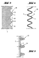
- Fig. 4 and in Fig. 5 is a bead-shaped or rib-shaped profiling shown.
- the bead-shaped profile 4 can be formed, for example, by a wall 2 made of corrugated iron the geometric shape of which is specifically tailored to the bulk material is.
- a rib-shaped profile 19 (FIG. 5) can, for example a smooth wall 2 can also be retrofitted.
- the Attachment of the rib-shaped profile can be done, for example, by Screw, rivet or welded connection.
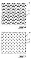
- the macroscopically rough inner surface of the silo wall through a waffle plate 27 (Fig. 6) or formed by a knobbed sheet 28 (Fig. 7).
- the polyhedral or ball shaped elevations of the waffle or Knob sheets are not sharp-edged. This ensures that the Wall friction coefficient of the silo is increased without it Abrasion or other damage to the bulk material comes.
- the Cell stem is a metal structure, this can be structured Sheets are advantageously fastened by means of riveted or welded connections become. It can completely or partially cover the inner surface of the cell shaft be carried out with such profiled sheets. Which embodiment to choose depends on the silo construction, the bulk material and the dynamic effects occurring when emptying.
- the Agents according to the invention can already in the construction and Production of the silo system can be provided. Existing silo systems can be easily retrofitted with these sheets.
- this is Means 26 according to the invention a sheet 21 with hole-shaped Recesses 20.
- the macroscopic roughness is determined by the thickness of the sheet and formed by the recesses 20.
- Fig. 8 is a sheet with round perforations
- Fig. 9 a sheet with Square perforation shown in diagonally staggered rows.
- the means 26 are formed by a grid 22 (Fig. 10).
- the grid 22 can be a steel grid, for example.
- the sheet 21 or the grid 22 can by means of a rivet connection 24 or Welded connection 25 to be attached to the wall 2 of the silo shaft.
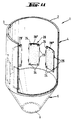
- FIG. 11 shows a preferred further development of a silo, in which only partial areas 29 ', 29 ", 29"' of the inner surface 3 of the Cell shaft 4 has a macroscopic roughness in the form of have structured sheets. These sheets can by means of Rivet connections 24 and / or weld connections 25 on the Inner surface 3 of the wall 2 attached.
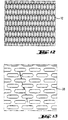
- FIG. 13 A commercially available expanded metal 32 is shown in FIG. Sheets with hole-shaped recesses, for example as an elongated hole 30 in Fig. 13 are shown in various materials, such as Aluminum and steel, commercially available.
- a so-called scale plate 31 is shown in Fig. 14.
- 15 and 16 show known basic designs of silos.
- the funnel-shaped part 5 inclined to the horizontal, the inner surface of the funnel therefore has an angle of inclination.
- the funnel consists of a horizontal bottom part.
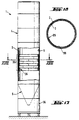
- the silo 17 is a round silo as an example according to the invention shown.
- the silo 1 is designed for mass flow.
- the shaft-shaped Part 4 is circular with a diameter of 3.5 m.
- the silo height is 20 m.
- the funnel 5 is drawn in dashed lines in FIG. 17.
- the shape of the Funnel 5 is conical.
- the silo 1 is supported by a support structure 34 supported.
- the wall of the silo is made up of cylindrical segments that consist of aluminum sheet, formed.
- the thickness of the aluminum sheets forms the wall thickness 7 of the silo and varies between 3.5 mm at the top and 7.5 mm at the bottom of the silo shaft.
- the sheet thickness in funnel-shaped part is 4 mm.
- the funnel is 3 m long and has an angle of 60 degrees. When silo is removed, the Mass flow between 10 and 12 tons per hour.
- silo When emptying this silo, which is filled with polymer granules was, at intervals of 7 to 15 seconds, pulse-shaped, very loud emptying noises. This "silo horn" sometimes occurred and only with certain polymer granules. There were volumes up to 100 dBA measured. The wall shear zone was about 5 to 10 cm.
- This silo was retrofitted by the Inner surface was made macroscopic rough.
- the Macroscopically rough inner surface was due to the installation commercially available waffle sheets.
- These were structured sheet metal only in a partial area of the inner surface identified in FIG. 17 appropriate.
- this partial area is a section 35 of a cylindrical surface and lies in the container at a height of 7.5 m to 11 m and covers the entire circumference of the round silo (Fig. 17).
- the sheets were in seven horizontal rows (7 x 0.5 m) and in five vertical columns (5 x 2.0 m) attached.
- the structured surface of the wafer sheet has polyhedral elevations with a height of 2 mm on.
- the waffle sheets were placed in the large container Rivet connection attached to the wall. There were commercial ones Aluminum sheets are used.
- a section through the silo 1 along the line XVIII-XVIII is in Fig. 18 shown.
- the inner surface 3 of the wall 2 has the agents 26 according to the invention.
- the means 26 commercially available Waffle tray. They extend along the preferred section 35 of the shaft-shaped part 4 of the round silo. It is particularly preferred if this section 35 lies at the transition between the core and the mass flow.
- the inventive Process the silo to be emptied so that no noise when Removal of bulk goods became audible.
- the silo system works trouble-free.
- a measurement of the acceleration on the cylinder wall shows that the vibration excitation of the wall by the invention could be significantly reduced.
- Dynamic loads during removal of bulk goods have an effect on the silo construction largely reduced by the invention.
Landscapes
- Engineering & Computer Science (AREA)
- Mechanical Engineering (AREA)
- Filling Or Emptying Of Bunkers, Hoppers, And Tanks (AREA)
- Storage Of Harvested Produce (AREA)
- Drying Of Solid Materials (AREA)
Description
- Figur 1
- ein Silo in schematischer geschnittener Darstellung, ohne Haltekonstruktion;
- Figur 2
- eine erfindungsgemäß makroskopisch rauh gestaltete Innenfläche eines Silos in einer Ausschnittsdarstellung;
- Figur 3
- eine Ausführungsform einer erfindungsgemäß gestalteten Innenfläche eines Stahlbetonsilos;
- Figur 4
- eine erfindungsgemäß makroskopisch rauh gestaltete Innenfläche einer Silowand mit sickenförmiger Profilierung;
- Figur 5
- eine erfindungsgemäß makroskopisch rauh gestaltete Silowand mit einer rippenförmigen Profilierung;
- Figur 6
- ein Waffelblech mit polyederförmigen Erhebungen;
- Figur 7
- ein Noppenblech mit ballenförmigen Erhebungen;
- Figur 8
- ein Blech mit lochförmigen Ausnehmungen;
- Figur 9
- ein Blech mit Quadratlochung;
- Figur 10
- ein an der Silowand befestigtes Gitter;
- Figur 11
- eine bevorzugte Weiterbildung der Erfindung, bei der nur ein Teilbereich der Innenfläche des Zellenschafts eine makroskopische Rauhigkeit aufweist;
- Figur 12
- ein strukturiertes Blech in Form eines Streckgitters;
- Figur 13
- ein strukturiertes Blech mit Langlöchern;
- Figur 14
- ein strukturiertes Blech in Form eines Schuppenbleches;
- Figur 15
- eine Grundbauform eines Silos mit einem konischen Trichter;
- Figur 16
- ein Grundbauform eines Silos mit ebener Bodenplatte;
- Figur 17
- ein erfindungsgemäßer Rundsilo;
- Figur 18
- ein Schnitt gemäß der Linie XVIII - XVIII in Figur 17.
Claims (13)
- Verfahren zur Verminderung von geräuschverursachenden Schwingungen eines Behälters, insbesondere eines Silos, bei der Entnahme von Schüttgut aus dem Behälter, derbei dem bei Entnahme von Schüttgut aus dem Behältermit einem schaftförmigen und einem trichterförmigen Teil (4,5) versehen ist, wobei der schaftförmige Teil (4) des Behälters eine im wesentlichen lotrechte Wand (2) mit einer Öffnung (12) zum Füllen aufweist,das Schüttgut durch eine Auslaßöffnung (6) im trichterförmigen Teil (5) austritt und an der Wand (2) des schaftförmigen Teils sich mit einer Geschwindigkeit (9) vorbeibewegt,wobei die Geschwindigkeit (9) des Schüttgutes nahe an der Wand (2) durch eine makroskopische Rauhigkeit zumindest eines Teilbereichs der Innenfläche (3) der Wand (2) so verringert wird, daß sich eine breite Wandscherzone (33) ausbildet, wodurch geräuschverursachende Schwingungsanregungen der Wand (2) vermindert werden.
- Verfahren nach Anspruch 1, dadurch gekennzeichnet, daß die makroskopische Rauhigkeit der Innenfläche (3) der Wand (2) dadurch gebildet wird, daßdie Innenfläche (3) eine Profilierung (19) aufweist,die Profilierung (19) Erhebungen (13) und/oder Vertiefungen (14) aufweist,jeweils Vertiefungen (14) bzw. benachbarte Erhebungen (13) und/oder Vertiefungen (14) zum Schüttgut hin einen offenen Halbraum (18) bilden,das Schüttgut (8) aus Teilchen (16) besteht, die einen mittleren Korndurchmesser aufweisen, undder Halbraum (18) so gewählt ist, daß der mittlere Korndurchmesser der Teilchen (16) des Schüttgutes (8) zumindest teilweise in den Halbraum (18) paßt.
- Verfahren nach Anspruch 2, dadurch gekennzeichnet, daß die Profilierung (19) einen makroskopischen Mittenrauhwert aufweist, der so groß wie ein fünftel des mittleren Korndurchmessers, besonders bevorzugt so groß wie der mittlere Korndurchmesser der Teilchen (16) des Schüttgutes (8) ist.
- Verfahren nach Anspruch 2, dadurch gekennzeichnet, daß die Innenfläche (3) einen Teilbereich (29) aufweist, der Teilbereich (29) eine Profilierung (19) aufweist und diese Profilierung (19) durch ein Waffelblech (27) oder durch ein Noppenblech (28) ausgebildet ist.
- Verfahren nach Anspruch 1, dadurch gekennzeichnet, daß die makroskopische Rauhigkeit an der Wand durch ein Blech (21) mit lochförmigen Ausnehmungen (20) oder durch ein Gitter (22) gebildet wird und daß das Blech (21) oder das Gitter (22) mittels einer Nietverbindung oder einer Schweißverbindung an der Wand (2) befestigt ist.
- Vorrichtung zur Verhinderung von geräuschverursachenden Schwingungen eines Behälters, insbesondere eines Silos, bei der Entnahme von Schüttgut aus dem Behälter, mitdadurch gekennzeichnet, daßeinem schaftförmigen und einem trichterförmigen Teil (4,5), wobeider schaftförmige Teil (4) des Behälters mindestens eine im wesentlichen lotrechte Wand (2) mit einer Innenfläche (3) und einer Öffnung (12) zum Füllen aufweist,der trichterförmige Teil (5) eine Auslaßöffnung (6) zur Entnahme von Schüttgut aufweist unddas Schüttgut bei Entnahme aus dem Behälter aus der Auslaßöffnung austritt und sich an der Wand (2) des schaftförmigen Teils mit einer Geschwindigkeit (9) vorbeibewegt,an der Innenfläche (3)der Wand (2) des schaftförmigen Teils (4) zumindest in einem Teilbereich Mittel (26) zur Schaffung einer makroskopischen Rauhigkeit und damit zur Schaffung einer breiten Wandscherzone (33) angeordnet sind, die die Geschwindigkeit (9) des Schüttgutes nahe an der Wand (2) so verringert, daß eine geräuschverursachende Schwingungsanregung der Wand (2) bei der Entnahme des Schüttgutes vermindert wird.
- Vorrichtung nach Anspruch 6, dadurch gekennzeichnet, daß die makroskopisch rauhe Innenfläche (3) durch eine Profilierung (19) dadurch gebildet wird, daßdie Profilierung (19) Erhebungen (13) und/oder Vertiefungen (14) aufweist,jeweils Vertiefungen (14) bzw. benachbarte Erhebungen (13) und/oder Vertiefungen (14) zum Schüttgut hin einen offenen Halbraum bilden,der Halbraum (18) so gewählt ist, daß der mittlere Korndurchmesser der Teilchen (16) des Schüttgutes (8) zumindest teilweise in den Halbraum (18) paßt.
- Vorrichtung nach Anspruch 6, dadurch gekennzeichnet, daßdie Wand (2) des schaftförmigen Teils (4) eine Blechwand ist,die Blechwand eine Innenfläche (3) mit einem Teilbereich (29) aufweist,der Teilbereich (29) eine Profilierung (19) aufweist, die durch ein Waffelblech (27) oder durch ein Noppenblech (28) gebildet sind, welches mittels einer Nietverbindung (24) oder einer Schweißverbindung (25) an der Blechwand befestigt ist.
- Vorrichtung nach Anspruch 7 oder 8, dadurch gekennzeichnet, daß die Profilierung (19) einen makroskopischen Mittenrauhwert aufweist, der so groß wie ein fünftel des mittleren Korndurchmessers, besonders bevorzugt so groß wie der mittlere Korndurchmesser der Teilchen (16) des Schüttgutes (8) ist.
- Vorrichtung nach Anspruch 6, dadurch gekennzeichnet, daß die makroskopsich rauhe Innenfläche (3) der Wand (2) durch eine Profilierung (19) eines Waffelbleches (27) oder eines Noppenbleches (28) gebildet wird.
- Vorrichtung nach Anspruch 6, dadurch gekennzeichnet, daß die makroskopisch rauhe Innenfläche (3) der Wand (2) durch eine Profilierung (19) eines Lochbleches (30) oder eines Schuppenbleches (31) oder eines Streckgitters (32) gebildet wird, welches in einem Teilbereich (29) des schaftförmigen Teils (4) mittels einer Nietverbindung (24) oder einer Schweißverbindung (25) befestigt ist.
- Vorrichtung nach Anspruch 8 oder 9, dadurch gekennzeichnet, daß die Innenfläche (3) der Wand (2) eine Mantelfläche eines Kreiszylinders bildet und der Teilbereich (29) ein Abschnitt (35) dieser Mantelfläche ist.
- Vorrichtung nach Anspruch 7 und 12, dadurch gekennzeichnet, daß der Abschnitt (35) zum trichterförmigen Teil (5) einen Abstand aufweist, der kleiner als der Durchmesser des Kreiszylinders ist.
Applications Claiming Priority (3)
| Application Number | Priority Date | Filing Date | Title |
|---|---|---|---|
| DE19606721A DE19606721A1 (de) | 1996-02-23 | 1996-02-23 | Verminderung von dynamischen Effekten bei der Entleerung von Silos |
| DE19606721 | 1996-02-23 | ||
| PCT/EP1997/000856 WO1997030915A1 (de) | 1996-02-23 | 1997-02-22 | Verminderung von dynamischen effekten bei der entleerung von silos |
Publications (2)
| Publication Number | Publication Date |
|---|---|
| EP0883561A1 EP0883561A1 (de) | 1998-12-16 |
| EP0883561B1 true EP0883561B1 (de) | 2000-05-03 |
Family
ID=7786176
Family Applications (1)
| Application Number | Title | Priority Date | Filing Date |
|---|---|---|---|
| EP97906111A Expired - Lifetime EP0883561B1 (de) | 1996-02-23 | 1997-02-22 | Verfahren und vorrichtung zur verminderung von geräuschverursachenden schwingungen bei der entleerung von silos |
Country Status (4)
| Country | Link |
|---|---|
| EP (1) | EP0883561B1 (de) |
| AT (1) | ATE192409T1 (de) |
| DE (2) | DE19606721A1 (de) |
| WO (1) | WO1997030915A1 (de) |
Cited By (3)
| Publication number | Priority date | Publication date | Assignee | Title |
|---|---|---|---|---|
| DE102004057226A1 (de) * | 2004-11-26 | 2006-06-08 | P+W Metallbau Gmbh & Co. Kg | Verfahren und Vorrichtung zur Verminderung von Geräuschen und Schwingungen bei der Entleerung von Silos |
| EP1801036A1 (de) | 2005-12-22 | 2007-06-27 | P+W Metallbau GmbH & Co. KG | Verfahren und Vorrichtung zur Verminderung von Geräuschen und Schwingungen bei der Entleerung von Silos |
| AU2018253634B1 (en) * | 2017-08-14 | 2018-12-20 | Tu Family Ip Pty Ltd | Silo dynamic vibration attenuation system and method |
Families Citing this family (3)
| Publication number | Priority date | Publication date | Assignee | Title |
|---|---|---|---|---|
| MX2020009126A (es) | 2018-03-08 | 2021-01-08 | Hyl Tech S A De C V | Contenedor, dispositivo y metodo para almacenar o procesar materiales en particulas para minimizar o eliminar vibraciones, como temblores o agitaciones. |
| DE102019118151B4 (de) | 2019-07-04 | 2022-12-22 | Markus Schinhärl | Speichervorrichtung für Schüttgut und Verfahren zum Speichern von Schüttgut |
| CN115285537B (zh) * | 2022-07-21 | 2023-09-01 | 长沙市奇俊机电科技有限公司 | 一种料仓实验系统 |
Family Cites Families (4)
| Publication number | Priority date | Publication date | Assignee | Title |
|---|---|---|---|---|
| US2741464A (en) * | 1953-07-07 | 1956-04-10 | Hewitt Robins Inc | Blending bin |
| FR1290269A (fr) * | 1961-03-01 | 1962-04-13 | Silos à fourrage et récipients de stockage | |
| BE731511A (de) * | 1968-05-10 | 1969-09-15 | ||
| DE4216853A1 (de) * | 1992-05-21 | 1994-02-24 | Ognjan Gruev | Anordnung an Silo-Zellen für radiale Ventilation |
-
1996
- 1996-02-23 DE DE19606721A patent/DE19606721A1/de not_active Ceased
-
1997
- 1997-02-22 AT AT97906111T patent/ATE192409T1/de active
- 1997-02-22 EP EP97906111A patent/EP0883561B1/de not_active Expired - Lifetime
- 1997-02-22 DE DE59701578T patent/DE59701578D1/de not_active Expired - Lifetime
- 1997-02-22 WO PCT/EP1997/000856 patent/WO1997030915A1/de not_active Ceased
Cited By (4)
| Publication number | Priority date | Publication date | Assignee | Title |
|---|---|---|---|---|
| DE102004057226A1 (de) * | 2004-11-26 | 2006-06-08 | P+W Metallbau Gmbh & Co. Kg | Verfahren und Vorrichtung zur Verminderung von Geräuschen und Schwingungen bei der Entleerung von Silos |
| EP1801036A1 (de) | 2005-12-22 | 2007-06-27 | P+W Metallbau GmbH & Co. KG | Verfahren und Vorrichtung zur Verminderung von Geräuschen und Schwingungen bei der Entleerung von Silos |
| AU2018253634B1 (en) * | 2017-08-14 | 2018-12-20 | Tu Family Ip Pty Ltd | Silo dynamic vibration attenuation system and method |
| WO2019033153A1 (en) * | 2017-08-14 | 2019-02-21 | Tu Phung | SYSTEM AND METHOD FOR MITIGATING DYNAMIC VIBRATIONS OF SILO |
Also Published As
| Publication number | Publication date |
|---|---|
| EP0883561A1 (de) | 1998-12-16 |
| WO1997030915A1 (de) | 1997-08-28 |
| DE59701578D1 (de) | 2000-06-08 |
| ATE192409T1 (de) | 2000-05-15 |
| DE19606721A1 (de) | 1997-08-28 |
Similar Documents
| Publication | Publication Date | Title |
|---|---|---|
| EP1959149B1 (de) | Luftlager mit Berücksichtigung hochfrequenter Resonanzen | |
| DE60310346T2 (de) | Verschlussstopfen für eine Öffnung in einem Bauteil | |
| DE2355254A1 (de) | Hydraulischer teleskopstossdaempfer und federungsanordnung mit einem solchen stossdaempfer | |
| DE3639091A1 (de) | Scherelement | |
| DE10143778A1 (de) | Vibrationsdämpfungsvorrichtung für ein Fahrzeug | |
| DE3606686A1 (de) | Viskosedaempfer fuer eine schwingungsisolierungsvorrichtung | |
| DE19606721A1 (de) | Verminderung von dynamischen Effekten bei der Entleerung von Silos | |
| CH618779A5 (en) | Sound-damping and vibration-damping fastening element, in particular for building construction | |
| DE3215428C2 (de) | Vorrichtung zur Schwingungsdämpfung an turmartigen Bauwerken wie Schornsteinen, Sendemasten o.dgl. | |
| EP0278325B1 (de) | Rahmen einer Abdeckung für eine durch einen Deckel oder Rost geschützte Öffnung | |
| WO2016037958A1 (de) | Einrichtung zum tilgen und dämpfen von schwingungen an bauwerken | |
| DE9311323U1 (de) | Schallabsorbierende Einrichtung für eine Schallisolationswand | |
| EP0443109B1 (de) | Vorrichtung zum Reinigen eines Abwasserkanals | |
| DE10145857B4 (de) | Lagerkonstruktion zur gedämpften Übertragung von Stoß- und/oder Schwingungskräften, insbesondere für Bauwerke, welche einer seismischen Belastung ausgesetzt sind | |
| EP0826834A2 (de) | Schachtabschluss | |
| EP0686733B2 (de) | Schwingungsdämpfer für schwingungsgefährdete Bauteile und Bauwerke | |
| DE2616899B2 (de) | Vorrichtung zur Schwingungsdämpfung an überschlanken Bauwerken wie Schornsteinen, Sendemasten o.dgl | |
| DE3703851C1 (de) | Zur Lagerung eines Motors in einem Kraftfahrzeug ausgebildeter Daempfungsblock | |
| EP1801036B1 (de) | Verwendung von Wandeinbauten zur Verminderung von Geräuschen und Schwingungen bei der Entleerung von Silos | |
| DE4418916A1 (de) | Schwingungsdämpfer für schwingungsgefährdete Bauwerke | |
| DE2144621A1 (de) | Schalldaemmendes trennwandelement | |
| CH659406A5 (en) | Method and device for damping shock waves in the explosive forming of workpieces | |
| DE3729865A1 (de) | Deckel fuer revisionsschaechte | |
| DE7703128U1 (de) | Prellbock fuer schiffe | |
| DE1634364C (de) | Gründung fur Gebäude, Gebäudeteile od dgl zum Schützen derselben gegen Zerstörung infolge heftiger Bewegungen ihrer Unterlage sowie Stutzkorper fur die se Gründung |
Legal Events
| Date | Code | Title | Description |
|---|---|---|---|
| PUAI | Public reference made under article 153(3) epc to a published international application that has entered the european phase |
Free format text: ORIGINAL CODE: 0009012 |
|
| 17P | Request for examination filed |
Effective date: 19980918 |
|
| AK | Designated contracting states |
Kind code of ref document: A1 Designated state(s): AT BE CH DE FR GB IT LI NL |
|
| 17Q | First examination report despatched |
Effective date: 19981202 |
|
| GRAG | Despatch of communication of intention to grant |
Free format text: ORIGINAL CODE: EPIDOS AGRA |
|
| RTI1 | Title (correction) |
Free format text: METHOD AND APPARATUS FOR THE REDUCTION OF NOISE GENERATING VIBRATIONS DURING SILO DISCHARGING |
|
| GRAG | Despatch of communication of intention to grant |
Free format text: ORIGINAL CODE: EPIDOS AGRA |
|
| GRAH | Despatch of communication of intention to grant a patent |
Free format text: ORIGINAL CODE: EPIDOS IGRA |
|
| GRAH | Despatch of communication of intention to grant a patent |
Free format text: ORIGINAL CODE: EPIDOS IGRA |
|
| GRAA | (expected) grant |
Free format text: ORIGINAL CODE: 0009210 |
|
| AK | Designated contracting states |
Kind code of ref document: B1 Designated state(s): AT BE CH DE FR GB IT LI NL |
|
| PG25 | Lapsed in a contracting state [announced via postgrant information from national office to epo] |
Ref country code: IT Free format text: LAPSE BECAUSE OF FAILURE TO SUBMIT A TRANSLATION OF THE DESCRIPTION OR TO PAY THE FEE WITHIN THE PRE;WARNING: LAPSES OF ITALIAN PATENTS WITH EFFECTIVE DATE BEFORE 2007 MAY HAVE OCCURRED AT ANY TIME BEFORE 2007. THE CORRECT EFFECTIVE DATE MAY BE DIFFERENT FROM THE ONE RECORDED.SCRIBED TIME-LIMIT Effective date: 20000503 |
|
| REF | Corresponds to: |
Ref document number: 192409 Country of ref document: AT Date of ref document: 20000515 Kind code of ref document: T |
|
| REG | Reference to a national code |
Ref country code: CH Ref legal event code: EP |
|
| REF | Corresponds to: |
Ref document number: 59701578 Country of ref document: DE Date of ref document: 20000608 |
|
| REG | Reference to a national code |
Ref country code: CH Ref legal event code: NV Representative=s name: TROESCH SCHEIDEGGER WERNER AG |
|
| GBT | Gb: translation of ep patent filed (gb section 77(6)(a)/1977) |
Effective date: 20000711 |
|
| ET | Fr: translation filed | ||
| PLBE | No opposition filed within time limit |
Free format text: ORIGINAL CODE: 0009261 |
|
| STAA | Information on the status of an ep patent application or granted ep patent |
Free format text: STATUS: NO OPPOSITION FILED WITHIN TIME LIMIT |
|
| 26N | No opposition filed | ||
| REG | Reference to a national code |
Ref country code: GB Ref legal event code: IF02 |
|
| PGFP | Annual fee paid to national office [announced via postgrant information from national office to epo] |
Ref country code: GB Payment date: 20130221 Year of fee payment: 17 Ref country code: CH Payment date: 20130225 Year of fee payment: 17 Ref country code: FR Payment date: 20130314 Year of fee payment: 17 |
|
| PGFP | Annual fee paid to national office [announced via postgrant information from national office to epo] |
Ref country code: AT Payment date: 20130225 Year of fee payment: 17 |
|
| PGFP | Annual fee paid to national office [announced via postgrant information from national office to epo] |
Ref country code: NL Payment date: 20140224 Year of fee payment: 18 Ref country code: DE Payment date: 20140225 Year of fee payment: 18 |
|
| PGFP | Annual fee paid to national office [announced via postgrant information from national office to epo] |
Ref country code: BE Payment date: 20140225 Year of fee payment: 18 |
|
| REG | Reference to a national code |
Ref country code: CH Ref legal event code: PL |
|
| REG | Reference to a national code |
Ref country code: AT Ref legal event code: MM01 Ref document number: 192409 Country of ref document: AT Kind code of ref document: T Effective date: 20140222 |
|
| GBPC | Gb: european patent ceased through non-payment of renewal fee |
Effective date: 20140222 |
|
| PG25 | Lapsed in a contracting state [announced via postgrant information from national office to epo] |
Ref country code: CH Free format text: LAPSE BECAUSE OF NON-PAYMENT OF DUE FEES Effective date: 20140228 Ref country code: LI Free format text: LAPSE BECAUSE OF NON-PAYMENT OF DUE FEES Effective date: 20140228 |
|
| REG | Reference to a national code |
Ref country code: FR Ref legal event code: ST Effective date: 20141031 |
|
| PG25 | Lapsed in a contracting state [announced via postgrant information from national office to epo] |
Ref country code: AT Free format text: LAPSE BECAUSE OF NON-PAYMENT OF DUE FEES Effective date: 20140222 |
|
| PG25 | Lapsed in a contracting state [announced via postgrant information from national office to epo] |
Ref country code: FR Free format text: LAPSE BECAUSE OF NON-PAYMENT OF DUE FEES Effective date: 20140228 Ref country code: GB Free format text: LAPSE BECAUSE OF NON-PAYMENT OF DUE FEES Effective date: 20140222 |
|
| PG25 | Lapsed in a contracting state [announced via postgrant information from national office to epo] |
Ref country code: BE Free format text: LAPSE BECAUSE OF NON-PAYMENT OF DUE FEES Effective date: 20150228 |
|
| REG | Reference to a national code |
Ref country code: DE Ref legal event code: R119 Ref document number: 59701578 Country of ref document: DE |
|
| REG | Reference to a national code |
Ref country code: NL Ref legal event code: V1 Effective date: 20150901 |
|
| PG25 | Lapsed in a contracting state [announced via postgrant information from national office to epo] |
Ref country code: NL Free format text: LAPSE BECAUSE OF NON-PAYMENT OF DUE FEES Effective date: 20150901 |
|
| PG25 | Lapsed in a contracting state [announced via postgrant information from national office to epo] |
Ref country code: DE Free format text: LAPSE BECAUSE OF NON-PAYMENT OF DUE FEES Effective date: 20150901 |