EP0883374B1 - Bobines mobiles de reception et d' emission pour systeme de localisation - Google Patents
Bobines mobiles de reception et d' emission pour systeme de localisation Download PDFInfo
- Publication number
- EP0883374B1 EP0883374B1 EP97904284A EP97904284A EP0883374B1 EP 0883374 B1 EP0883374 B1 EP 0883374B1 EP 97904284 A EP97904284 A EP 97904284A EP 97904284 A EP97904284 A EP 97904284A EP 0883374 B1 EP0883374 B1 EP 0883374B1
- Authority
- EP
- European Patent Office
- Prior art keywords
- transducers
- probe
- frame
- reference field
- patient
- Prior art date
- Legal status (The legal status is an assumption and is not a legal conclusion. Google has not performed a legal analysis and makes no representation as to the accuracy of the status listed.)
- Expired - Lifetime
Links
Images


Classifications
-
- A—HUMAN NECESSITIES
- A61—MEDICAL OR VETERINARY SCIENCE; HYGIENE
- A61B—DIAGNOSIS; SURGERY; IDENTIFICATION
- A61B5/00—Measuring for diagnostic purposes; Identification of persons
- A61B5/06—Devices, other than using radiation, for detecting or locating foreign bodies ; determining position of probes within or on the body of the patient
-
- A—HUMAN NECESSITIES
- A61—MEDICAL OR VETERINARY SCIENCE; HYGIENE
- A61B—DIAGNOSIS; SURGERY; IDENTIFICATION
- A61B34/00—Computer-aided surgery; Manipulators or robots specially adapted for use in surgery
- A61B34/20—Surgical navigation systems; Devices for tracking or guiding surgical instruments, e.g. for frameless stereotaxis
-
- A—HUMAN NECESSITIES
- A61—MEDICAL OR VETERINARY SCIENCE; HYGIENE
- A61B—DIAGNOSIS; SURGERY; IDENTIFICATION
- A61B5/00—Measuring for diagnostic purposes; Identification of persons
- A61B5/06—Devices, other than using radiation, for detecting or locating foreign bodies ; determining position of probes within or on the body of the patient
- A61B5/061—Determining position of a probe within the body employing means separate from the probe, e.g. sensing internal probe position employing impedance electrodes on the surface of the body
- A61B5/064—Determining position of a probe within the body employing means separate from the probe, e.g. sensing internal probe position employing impedance electrodes on the surface of the body using markers
-
- A—HUMAN NECESSITIES
- A61—MEDICAL OR VETERINARY SCIENCE; HYGIENE
- A61B—DIAGNOSIS; SURGERY; IDENTIFICATION
- A61B90/00—Instruments, implements or accessories specially adapted for surgery or diagnosis and not covered by any of the groups A61B1/00 - A61B50/00, e.g. for luxation treatment or for protecting wound edges
- A61B90/36—Image-producing devices or illumination devices not otherwise provided for
-
- A—HUMAN NECESSITIES
- A61—MEDICAL OR VETERINARY SCIENCE; HYGIENE
- A61B—DIAGNOSIS; SURGERY; IDENTIFICATION
- A61B17/00—Surgical instruments, devices or methods, e.g. tourniquets
- A61B2017/00681—Aspects not otherwise provided for
- A61B2017/00725—Calibration or performance testing
-
- A—HUMAN NECESSITIES
- A61—MEDICAL OR VETERINARY SCIENCE; HYGIENE
- A61B—DIAGNOSIS; SURGERY; IDENTIFICATION
- A61B34/00—Computer-aided surgery; Manipulators or robots specially adapted for use in surgery
- A61B34/20—Surgical navigation systems; Devices for tracking or guiding surgical instruments, e.g. for frameless stereotaxis
- A61B2034/2046—Tracking techniques
- A61B2034/2051—Electromagnetic tracking systems
-
- A—HUMAN NECESSITIES
- A61—MEDICAL OR VETERINARY SCIENCE; HYGIENE
- A61B—DIAGNOSIS; SURGERY; IDENTIFICATION
- A61B34/00—Computer-aided surgery; Manipulators or robots specially adapted for use in surgery
- A61B34/20—Surgical navigation systems; Devices for tracking or guiding surgical instruments, e.g. for frameless stereotaxis
- A61B2034/2072—Reference field transducer attached to an instrument or patient
-
- A—HUMAN NECESSITIES
- A61—MEDICAL OR VETERINARY SCIENCE; HYGIENE
- A61B—DIAGNOSIS; SURGERY; IDENTIFICATION
- A61B90/00—Instruments, implements or accessories specially adapted for surgery or diagnosis and not covered by any of the groups A61B1/00 - A61B50/00, e.g. for luxation treatment or for protecting wound edges
- A61B90/36—Image-producing devices or illumination devices not otherwise provided for
- A61B2090/363—Use of fiducial points
-
- A—HUMAN NECESSITIES
- A61—MEDICAL OR VETERINARY SCIENCE; HYGIENE
- A61B—DIAGNOSIS; SURGERY; IDENTIFICATION
- A61B90/00—Instruments, implements or accessories specially adapted for surgery or diagnosis and not covered by any of the groups A61B1/00 - A61B50/00, e.g. for luxation treatment or for protecting wound edges
- A61B90/36—Image-producing devices or illumination devices not otherwise provided for
- A61B90/37—Surgical systems with images on a monitor during operation
- A61B2090/376—Surgical systems with images on a monitor during operation using X-rays, e.g. fluoroscopy
-
- A—HUMAN NECESSITIES
- A61—MEDICAL OR VETERINARY SCIENCE; HYGIENE
- A61B—DIAGNOSIS; SURGERY; IDENTIFICATION
- A61B90/00—Instruments, implements or accessories specially adapted for surgery or diagnosis and not covered by any of the groups A61B1/00 - A61B50/00, e.g. for luxation treatment or for protecting wound edges
- A61B90/39—Markers, e.g. radio-opaque or breast lesions markers
- A61B2090/3925—Markers, e.g. radio-opaque or breast lesions markers ultrasonic
- A61B2090/3929—Active markers
-
- A—HUMAN NECESSITIES
- A61—MEDICAL OR VETERINARY SCIENCE; HYGIENE
- A61B—DIAGNOSIS; SURGERY; IDENTIFICATION
- A61B90/00—Instruments, implements or accessories specially adapted for surgery or diagnosis and not covered by any of the groups A61B1/00 - A61B50/00, e.g. for luxation treatment or for protecting wound edges
- A61B90/39—Markers, e.g. radio-opaque or breast lesions markers
- A61B2090/3954—Markers, e.g. radio-opaque or breast lesions markers magnetic, e.g. NMR or MRI
- A61B2090/3958—Markers, e.g. radio-opaque or breast lesions markers magnetic, e.g. NMR or MRI emitting a signal
-
- A—HUMAN NECESSITIES
- A61—MEDICAL OR VETERINARY SCIENCE; HYGIENE
- A61B—DIAGNOSIS; SURGERY; IDENTIFICATION
- A61B90/00—Instruments, implements or accessories specially adapted for surgery or diagnosis and not covered by any of the groups A61B1/00 - A61B50/00, e.g. for luxation treatment or for protecting wound edges
- A61B90/39—Markers, e.g. radio-opaque or breast lesions markers
- A61B2090/397—Markers, e.g. radio-opaque or breast lesions markers electromagnetic other than visible, e.g. microwave
- A61B2090/3975—Markers, e.g. radio-opaque or breast lesions markers electromagnetic other than visible, e.g. microwave active
-
- A—HUMAN NECESSITIES
- A61—MEDICAL OR VETERINARY SCIENCE; HYGIENE
- A61B—DIAGNOSIS; SURGERY; IDENTIFICATION
- A61B90/00—Instruments, implements or accessories specially adapted for surgery or diagnosis and not covered by any of the groups A61B1/00 - A61B50/00, e.g. for luxation treatment or for protecting wound edges
- A61B90/39—Markers, e.g. radio-opaque or breast lesions markers
- A61B2090/3983—Reference marker arrangements for use with image guided surgery
-
- A—HUMAN NECESSITIES
- A61—MEDICAL OR VETERINARY SCIENCE; HYGIENE
- A61B—DIAGNOSIS; SURGERY; IDENTIFICATION
- A61B90/00—Instruments, implements or accessories specially adapted for surgery or diagnosis and not covered by any of the groups A61B1/00 - A61B50/00, e.g. for luxation treatment or for protecting wound edges
- A61B90/10—Instruments, implements or accessories specially adapted for surgery or diagnosis and not covered by any of the groups A61B1/00 - A61B50/00, e.g. for luxation treatment or for protecting wound edges for stereotaxic surgery, e.g. frame-based stereotaxis
- A61B90/11—Instruments, implements or accessories specially adapted for surgery or diagnosis and not covered by any of the groups A61B1/00 - A61B50/00, e.g. for luxation treatment or for protecting wound edges for stereotaxic surgery, e.g. frame-based stereotaxis with guides for needles or instruments, e.g. arcuate slides or ball joints
Definitions
- the present invention relates to systems for medical diagnosis and treatment, and specifically to using reference field transducers and medical probes with probe field transducers to detect the position, orientation, or both of the probe within the body of a subject.
- probes such as catheters
- cardiac catheterization and neurosurgery it is often necessary for the physician or surgeon to know the location of the distal end of the probe inside the body.
- imaging methods such as fluoroscopy and ultrasound are sometimes used for this purpose, they are not always practical or desirable.
- fluoroscopic systems are often undesirable because that they expose the patient and physician to substantial ionizing radiation.
- Systems such as those disclosed in the '091, '199 and '489 patents and in the '768 publication determine the disposition (i.e., position, orientation, or both) of a probe using one or more field transducers, such as a Hall effect devices, magnetoresistive devices, coils or other antennas carried on the probe.
- the transducers are typically located at or adjacent the distal end of the probe or at a precisely known location relative to the distal end of the probe.
- Such systems further utilize one or more reference field transducers disposed outside the body to provide an external frame of reference.
- the reference field transducers are operative to transmit or detect non-ionizing fields or field components such as magnetic field, electromagnetic radiation or acoustical energy such as ultrasonic vibration.
- the frame of reference of the external field transducers can be registered with the frame of reference of imaging data such as magnetic resonance imaging data, computerized axial tomographic ("CAT") data, or conventional x-ray imaging data, and hence the position and/or orientation data derived from the system can be displayed as a representation of the probe superimposed on an image of the patient's body.
- the physician can use this information to guide the probe to the desired location within the patient's body, and to monitor its location and orientation during treatment or measurement of the internal body structure.
- This arrangement greatly enhances the ability of the physician to navigate the distal end of the probe through bodily structures and offers significant advantages over conventional methods of navigating probes within the body by feel alone.
- transducer-based systems Because it does not require acquiring an optical image of the surrounding tissues for navigation purposes, it can be used with probes which are too small to accommodate optical elements. These transducer-based systems also avoid the difficulties associated with navigation of a probe by continuous imaging of the probe and patient during the procedure and avoids, for example, prolonged exposure to ionizing radiation inherent in fluoroscopic systems.
- Such systems typically utilize reference field transducers or coils which are provided in a fixed, immovable array, in locations such as on the ceiling of an operating room or rigidly fixed to operating or catheterization table.
- the coil mounting may also interfere with free access by the physician to the patient.
- the aforementioned '768 publication describes a catheter system which uses a plurality of non-concentric coils adjacent to the distal end of the catheter. These coils generate signals in response to externally applied magnetic fields, which allow for the computation of six location and orientation coordinates, so that the disposition of the catheter is known without the need for simultaneous imaging.
- three such coils or radiators are arrayed in fixed locations outside the body, adjacent to the area of the body into which the catheter is introduced.
- three radiators are typically fixedly placed beneath the patient's thorax, in a fixed coplanar, triangular arrangement, with the centers of the coils from about 2 to 30 cm apart. Undesired movement of this array of radiators, however, can lead to errors in determination of the location or orientation of the catheter.
- the transducers or field radiating coils should desirably be positioned adjacent to the patient's head.
- the patient is often in a seated, upright position or else face-down.
- a triangular frame holding the three radiators as described above cannot be comfortably and stably positioned below the head.
- positioning the frame above or beside the head will generally interfere with the surgeon's manipulation of probes and surgical tools.
- transducers In addition, it would be desirable to provide greater flexibility as to where the transducers are placed about the subject. Such increased placement flexibility would allow the physician to have easier access to the patient. Flexibility over placement of the transducers would allow custom positioning of the transducers to move them to the closest possible locations to increase sensitivity of the locating system.
- the present invention addresses the need of providing greater flexibility in the positioning of position determining transducers by providing a system for determining the disposition of a probe within the body of a patient as defined in claim 1, comprising a probe having one or more probe field transducers mounted therein and one or more reference field transducers mounted on a frame.
- the system includes means for mounting the frame for movement relative to the patient so that the reference field transducers can be selectively positioned in different positions in close proximity to the body of the patient.
- the mounting means may desirably comprise a flexible, goose neck arm.
- Transmission means are provided to transmit one or more non-ionizing fields between the probe field transducers and the reference field transducers and detection means detect each such transmitted field.
- calculation means determine the relative disposition of said probe with respect to said reference field transducers from properties of the detected fields and from the relative dispositions of said reference field transducers with respect to one another.
- two or more reference field transducers are provided and the frame incorporates a linkage so as to allow each of said reference field transducers to be movable in a known spatial relationship with respect to one another.
- One or more fiducial transducers are attached to the body of the patient, translate the disposition of said probe relative to said reference field transducers to a known deposition relative to the body of the patient.
- the frame is suitable for positioning the reference field transducers in close proximity to the subject's head without interfering with neurosurgical procedures.
- a further object of the present invention is that the frame may be quickly and conveniently fixed in a desired position for optimal transmission of non-ionizing fields into a part of the subject's body, preferably surrounding the part of the body, and quickly removed from the position thereafter.
- the reference field transducers are radiator coils which generate electromagnetic fields.
- the apparatus for generating non-ionizing fields comprises three transducers or coils fixed to a rigid frame.
- the frame is conveniently and stably positioned below the thorax or abdomen during insertion of probes therein.
- the apparatus for generating fields comprises three coils fixed to a frame below the head, in close proximity to the head.
- the frame includes an opening that is adapted to fit around the head or neck.
- three or more co-planar reference field transducers define a polygonal shape, wherein the transducers correspond to the vertices of the polygon.
- a section of the frame corresponding to a side of the polygon is open, and the frame is positioned so that a part of the body is partly contained in this open section.
- the frame may comprises a mounting bracket, which couples rigidly to the operating table, bed or other apparatus used for fixing the subject's position.
- the frame couples to apparatus for fixing the position of a subject's head during neurosurgery.
- one or more reference field transducers are fixed to the head fixing apparatus. Electromagnetic fields generated by the transducers cause them to generate position-responsive electrical signals, which are analyzed in order to determine and verify the position of the apparatus relative to the frame.
- the frame or the head fixing apparatus further include predetermined, known locations, which are marked on the frame or head fixing apparatus, wherein a probe for insertion into the body is first placed in these locations for calibration and reference positioning.
- the mounting bracket includes a fixable joint, which allows the angular orientation of the frame relative to the bed or relative to the head fixing apparatus to be adjusted and then rigidly fixed at a desired angle.
- the frame comprises one or more adjustment hinges. Each such hinge may be flexed so as to adjust the angle between two sides of the frame adjacent thereto, and then fixed rigidly at the desired angle.
- the frame comprises head rest fixtures.
- the positions of these fixtures may be adjusted so that the fixtures fit snugly against the head, so as to maintain the head in a fixed position relative to the reference field transducers and prevent motion of the head relative to the frame.
- apparatus for generating non-ionizing fields inside the body of a subject comprising a plurality of reference field transducers, which generate non-ionizing fields, and a rigid frame to which the transducers are fixed.
- the rigid frame is constructed so as to allow the reference field transducers to be fixably positioned in close proximity to the body.
- the transducers define a polygon
- the frame is constructed so as to be positionable so that an axis perpendicular to the plane of the polygon and passing through the its center passes through the body.
- the frame is preferably constructed so as to be positionable so that a part of the body is substantially inside the polygon.
- the frame includes a mounting bracket, which couples rigidly to an operating table or bed.
- the mounting bracket preferably includes a fixable joint, which is constructed so as to allow the frame to be adjusted and fixed at a desired angle relative to the operating table or bed.
- the frame may preferably include a plurality of arms and an adjustment hinge, which couples two or more of the arms and is constructed so as to allow an angle defined by the two or more arms that it couples to be adjusted and fixed rigidly in a desired position.
- the frame be adapted so that the reference field transducers are fixably positioned in close proximity to the head and generate non-ionizing fields in a vicinity of the head.
- the frame is mechanically coupled to apparatus for fixing the position of the head during surgery.
- the frame may be adapted to fix the position of the head during surgery.
- the frame may further comprise head engaging elements, which bear against opposite sides of the head.
- the transducers are coils which generate magnetic fields.
- a system for determining the position and orientation of a probe inside the body of a subject including apparatus for generating fields, as described above; a probe for insertion into the body; and at least one device responsive to the fields for determining position and orientation coordinates of the probe.
- this system includes one or more position sensing devices, preferably fixed to the probe, and adapted so to allow the positions of the transducers to be determined.
- the fields are magnetic fields, and the field responsive device is a coil.
- the frame preferably further includes probe calibration receptacles.
- the frame preferably comprises a pair of arm members defining a triangle having two closed sides and an open side such that a portion of the head or neck can be readily positioned within the frame through the open side.
- transducers are positioned at at least the three corners of the frame and the arm members of the frame are hingedly connected to one another. Further, means for measuring the relative displacement between the arm members can be provided.
- the head clamp may be attached to the frame to prevent movement of the head.
- the frame may be integrally formed with a head clamp to prevent movement of the head.
- the frame may further include head engaging fixtures adjustable to tighten to the head.
- Fig. 1 shows a system for determining the position, orientation, or both of a probe, such as a catheter 20, disposed inside the body of a subject in use during a cardiac catheterization procedure, in accordance with a preferred embodiment of the present invention.
- the system is of a type described in the above mentioned '768 publication.
- the system includes means for generating the disposition of the distal end of the probe or catheter 20.
- disposition refers to the position, the orientation, or both of the probe or transducer.
- the probe includes a plurality of transducers in the form of non-concentric receiver coils 21 (only one being shown) adjacent to a locatable site in the catheter, for example near its distal end.
- These coils generate signals in response to magnetic fields generated by reference field transducers 22, fixed to a frame 23, which is in turn fixed to operating table 24 beneath thorax 26 of subject 28.
- the signals allow for the determination of six location and orientation coordinates, so that the disposition of catheter 20 is known without the need for simultaneous imaging.
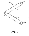
- Fig. 2 shows a schematic view of one aspect of the present invention which comprises a frame 22, to which three reference field transducers 30, 32 and 34 are fixed, in accordance with a preferred embodiment of the present invention.
- Frame 22 is preferably made of hard plastic or other rigid material and so mounted as to prevent motion of the reference field transducers during the catheterization or other medical procedure.
- Transducers 30, 32 and 34 are preferably field generating coils, which generate a multiplicity of distinguishable AC magnetic fields when driven by field generating circuits (not shown in the figure).
- transducers 30, 32 and 34 will be of approximately equal and maximal amplitudes in a region adjacent to an axis A that passes through the center of the triangle defined by the transducers and is perpendicular to the plane thereof. Empirically it has been found that the position of the probe and hence the catheter is determined with greatest accuracy in this region.
- the magnetic fields generated by transducers 30, 32 and 34 are distinguishable by virtue of having different AC frequencies.
- the transducers are coils, which are driven by driver circuitry (not shown in the figures) at respective resonant frequencies thereof and generate magnetic fields having substantially equal amplitudes at these frequencies.
- driver circuitry not shown in the figures
- D 2 given two resonant coils of respective diameters D 1 and D 2 , and respective frequencies ⁇ 1 and ⁇ 2 , if ⁇ 1 > ⁇ 2 and both coils are driven at equal levels of input power, then D 2 must generally be greater than D 1 in order that the amplitudes of the magnetic fields at the respective frequencies ⁇ 1 and ⁇ 2 be substantially equal. Therefore, transducers 30, 32 and 34 are preferably of different diameters, as shown, for example, in Fig. 8B, with the coil whose resonant frequency is largest having the smallest diameter, and vice-versa.
- transducers 30, 32 and 34 are fixed to frame 22 so as to define an isosceles triangle.
- this triangle is not equilateral, but rather has an apex that is more acute than the other two vertices, so that the frame may fit easily under operating table 24 (Fig. 1) without protruding at the sides.
- the largest of the coils is positioned at the apex of the triangle.
- Fig. 2 shows a triangular frame 22 and three transducers 30, 32 and 34
- the frame to which the transducers are fixed may be of some other polygonal or non-polygonal shape, which may be planar or non-planar, so long as the shape of the frame is such as to allow the transducers to be stably positioned adjacent to the portion of the body where the probe is located.
- the frame is positioned and oriented so that the portion of the body where the probe is located is adjacent to a central axis defined by the positions of the transducers.
- center and central in this context are taken to refer to the center of an equilateral polygon, if the transducers define such a geometrical figure, or to the geometrical center of mass of a figure defined by the transducers, as determined according to methods known in the art.
- a system for determining disposition of a probe preferably a catheter 40, inside the head 42 of a subject 44, is used during neurosurgery.
- the system is of a type described in the above mentioned '103 PCT patent application, although the preferred embodiment of the invention shown in Fig. 3 is equally applicable to other types of systems for determining probe disposition .
- Frame 38 holds reference field transducers 30, 32 and 34 adjacent to the head 42 of subject 44.
- frame 38 comprises rigid arms 36 and 37, which form two sides of a triangle. Arms 36 and 37 are preferably made of hard plastic or other rigid material. The third side of the triangle is open, so that the rear portion of head 42 of patient 44 can be positioned in the space between arms 36 and 37, as shown in Fig. 3. In this way transducers 30, 32 and 34 are positioned so that head 42 is located within the region wherein the position of catheter 40 may be determined most accurately, as explained above.
- frame 38 may be fixed by a mounting bracket 50 to operating table 46, which is positioned so as to maintain the patient in a sitting position during surgery.
- Head clamp 47 is fixed to table 46 and is fastened tightly to head 42 so as to prevent motion of the head. It will be appreciated that surgeon 48 is free to operate on the front portion of head 42, unhampered by frame 38.
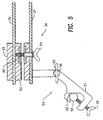
- bracket 50 comprises a clamp 51 with a groove 52 that engages rail 54, which is rigidly attached to table 46.
- a thumbscrew 56 is tightened against rail 54 to hold the bracket in the desired position.
- Bracket 50 is coupled to frame 38 by a fixable joint 58, which is preferably a ball joint. After joint 58 has been positioned at the desired angle, thumbscrew 60 is tightened to hold joint 58 rigidly in position.
- adjustable hinge 62 allows the angle between arms 36 and 37 of frame 38 to be adjusted. After the arms are set to the desired angle, thumbscrew 64 is tightened to prevent further motion of the hinge.
- Hinge 62 preferably includes a rotation measuring device 65, of a type known in the art, such as an optical encoder device, which allows the angle between arms 36 and 37 to be accurately determined, so that the relative positions of transducers 30, 32 and 34 are known.
- frames to which transducers are fixed in accordance with the present invention may include hinges or joints that allow angles and the displacement between arms of the frames to be varied, so as to position the transducers optimally in proximity to a part of the body of a subject, for accurate determination of the position of a probe therein.
- Frames in accordance with these embodiments may preferably include means, known in the art, for measurement of the angles and displacement between the arms of the frames.
- the relative positions of the transducers with respect to one another can be determined through geometric methods such as by measuring the angles between the transducers or displacement of the arms which carry the transducers, other methods may be used.
- one or more calibration field transducers can be provided in association with each reference field transducer.
- the calibration transducers determine the relative positions of the field transducers with respect to one another after they are located in their desired positions by the transmitting and detecting non-ionizing fields between the calibration and reference field transducers.
- a device for generating position information is placed adjacent to each of the transducers on the frame, thereby allowing the relative positions of the transducers to be accurately determined.
- These devices for generating position information may, for example, comprise transducers such as sensor coils, which generate position-responsive electrical signals in response to externally-applied magnetic fields, and which signals are analyzed in order to determine the position of the apparatus relative to the frame.
- frame 38 includes head engaging fixtures 70 at the ends of arms 36 and 37 that are adjacent to the head. Fixtures 70 are adjusted and tightened so as to bear firmly against opposite sides of the head, for example by turning thumbscrews 68 to advance threaded rods 66, coupled to fixtures 70, through respective threaded holes in arms 36 and 37. Thus, transducers 30, 32 and 34 are maintained in fixed positions relative to the head during the entire surgical operation. Furthermore, in this embodiment frame 38 may also be useful in holding head 42 in a desired orientation relative to operating table 46, in conjunction with head clamp 47.
- transducers 30, 32 and 34 are fixed to a rigid head clamp 71, which thereby serves as the frame for mounting the radiators in accordance with the invention.
- Head clamp is preferably fastened to the patient's head in a similar manner to head clamp 47, shown in Fig. 3.
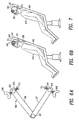
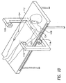
- Figs. 8A and 8B show another preferred embodiment of the present invention, useful in ensuring that the positions of transducers 30, 32 and 34 are securely fixed, and will not move in the course of the surgical operation.
- Fig. 8A shows a frame 72 attached to an operating table 94.
- Frame 72 includes mounts 74 to which transducers 30, 32 and 34 are fixed.
- frame 72 further comprises two pairs of pin receptacles 76 and 78 on opposing sides of the frame, which are engaged by hinge pins 80 and guide pins 82 respectively.
- Frame 72 may be made of a single, rigid piece of material, which is preferably plastic.
- Hinge pins 80 engage holes in guide rings 84 and in holders 86 on both sides of frame 72, so that the frame may rotate about an axis 88 defined by the pair of pins 80, as shown in Fig. 8B.
- Guide pins 82 engage slots 90 of guide rings 84, so that as frame 72 rotates about axis 88, pins 82 slide along the slots.
- Holders 86 are engaged by rods 92, which couple frame 72 and guide rings 84 to operating table 94.
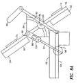
- a subject lies on mattress 95 of operating table 94, with his head in contact with and clamped firmly to head support 96, whose details are not shown in the figure.
- Frame 72 is rotated about axis 88 so as to position radiators fixed to mounts 74 in the desired positions adjacent to the head.
- Knobs 98, 100, 102 and 104 are then tightened to hold frame 72 rigidly in the desired orientation.
- Knobs 98 and 104 together prevent motion of rods 92, while knobs 100 tighten guide pins 82 in slots 90, and knobs 102 prevent rotation of hinge pins 80 in holders 86. This redundancy of tightening knobs ensures that frame 72 will not move accidentally.
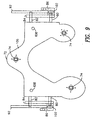
- Fig. 9 shows an alternative preferred embodiment of the present invention, wherein frame 106 is identical in operation to frame 72 shown in Figs. 8A and 8B. In the embodiment shown in Fig. 9, however, the portion of frame 106 that engages pins 80 and 82 is made wider, so that the frame will hold its position relative to table 94 with greater rigidity when fixed by tightening knobs 98, 100, 102 and 104.
- Frame 106 further includes catheter calibration receptacles 108, positioned in known locations relative to transducers mounts 74.
- the catheter is calibrated by placing the distal tip thereof, which carried the probe, in each of receptacles 108 in turn, and comparing the respective known position of the receptacle with position information derived from signals generated by position information generating means in the catheter, as described above.
- the calibration data derived from this procedure may be used in conjunction with calibration data stored in the catheter, as described in an unpublished U.S. provisional patent application 60/017,634 by Osadchy, Fried and Ben-Haim, entitled, "Catheter Calibration System,” and filed on May 17, 1996.
- a U-shaped frame 110 provides a stable mount for transducers 122, 124 and 126 attached thereto, which may be used as part of a system for tracking a probe inside the abdomen of the patient 128.
- Frame 110 allows transducers 122 and 126 to be positioned above the left and right sides of the abdomen respectively, while transducer 124 is positioned below the back.
- Frame 110 is connected to operating table 112 by mounting mechanism 114, which is similar in function and construction to mounting bracket 50, as shown in Fig. 5.
- Mechanism 114 allows the frame to tilt from side to side and to be suitably slid back and forth along the length of table 112, until it is locked in the desired position.
- a movable transducer assembly 300 also referred to as a "goose-neck" mini-radiator, which includes one or more reference field transducers 302 which are preferably field transmitting coils of a very small size, and may incorporate ferrite cores. Small coils are preferred since they tend to act more like point source dipoles which provides more accurate calculations by the computer of probe disposition.
- Each coil 302 is attached to a coil retaining arm 304 forming support 306, which is preferably formed of a lightweight material such as plastic.
- attachment bolt 308 At the center of support 306 is attachment bolt 308 which allows the support to be attached to a flexible, goose neck arm 310 as shown in Fig.
- the entire movable transducer assembly 300 may be mounted to an operating table or the like by an adjustable mounting mechanism 312, which includes a movable bracket 314 tightenable against upper arm 316 by rotation of tightening screw 318.
- a support disk 309 is optionally included to provide enhanced support to the coils 302. Support disk 309, however, can be eliminated in situations where undesirable shadows may be cast due to lighting in the room in which the patient is located.
- three transducers 302 are preferred, one, two or more than three transducers can be used.
- a single multi-axis, solid-state position sensor can be used where the probe transducers comprises field generating transducers.
- one or more patient reference transducers 320 are attached to the body of patient 322 and used to determine the position of the transducers on the movable transducer assembly 300 with respect to the patient frame of reference after the movable transducer assembly is moved to its desired position.
- patient reference transducer 320 comprises a solid-state 3-axis position sensor.
- the movable transducer assembly 300 shown in Figs. 11A and 11B is only one example of the support that can be used to provide readily repositionable reference field transducers.
- Other means for providing a movable and repositionable support can be employed, such as replacing goose neck arm 310 with a number of smaller rigid arm members attached to one another by adjustable and tightenable joints such as the joint and thumbscrew arrangement shown in Fig. 5.
- more than three coils can be employed on the movable transducer assembly and the coils need not be set in a co-planar relationship, so long as the relative positions among the coils is known or determinable.
- the movable transducer assembly is movable close to the region of interest during the surgical procedure and also repositionable away from areas to which the surgeon must gain access.
- the movable transducer assembly is small and directable thereby providing an adjustable and stable suspension system for the field transducers for directing the fields created to the only the particular volume of tissue to be image correlated.
- Superior signal-to-noise ratio performance is also achieved with the movable transducer assembly of the present invention.
- a region of volume associated with the transducers in which the signal-to-noise ratio of the assembly is optimized allowing higher accuracy field measurements to be made.
- this optimal region will typically encompass a large area to account for possible movement of the probe throughout the patient. For example, if the probe such as a catheter must be tracked from the leg of the patent to the heart, the optimal region defined by the fixed transducers must be large enough to cover most of the patient.
- this optimal area can be made smaller and highly concentrated since the assembly is movable, even during the surgical procedure, to the region of interest of the patient, Accordingly, preferred embodiments of the present invention can provide enhanced signal-to-noise performance in comparison to a fixed transducer assembly using the same transducers in a large fixed array.
- the signal-to-noise performance of the system also depends on the properties of the probe transducer.
- the enhanced performance provided by preferred embodiments of the present invention can provide acceptable signal-to-noise performance with a less sensitive probe transducer, which in turn facilitates miniaturization of the probe transducer and probe.
- the benefit provided by the movable transducer assembly can permit use of smaller, cheaper and less obtrusive reference transducers while maintaining satisfactory performance.
- the movable transducer assembly can be optimally positioned so as not to obstruct the view of the assistant surgeon nor obstruct access to the patient.
- the movable transducer assembly may be attached to the operating bed rail and may be slid up and down the rail as desired. Since a patient reference transducer may be provided to account for the movement of the reference field transducers with respect to the patient, re-registration with the pre-acquired image data is readily accomplished.
- system software can also be provided and feedback techniques can be used to correct inappropriate placement of the movable transducer assembly. For instance, an indicator signal such as a light or tone can be generated when the positioning of the reference field transducers is too remote from the position sensor on the distal tip of the probe to generate reliable field detection and position information.
- an indicator signal such as a light or tone can be generated when the positioning of the reference field transducers is too remote from the position sensor on the distal tip of the probe to generate reliable field detection and position information.
- small point source electromagnets are advantageous since they are lightweight and can therefore be readily and easily moved into desired positions, or out of the way of the physician, during a surgical procedure.
- the use of small point source electromagnets also allows more accurate computer modeling since the coils behave as better dipoles as compared to presently used fixed coil systems.
- non-movable coil systems can obstruct the physicians and can block the assistant surgeon from standing opposite from the primary surgeon.
- Non-movable coil systems cannot generally be positioned above the patient as they would block the lighting.
- non-movable coil systems may not be positionable under the patient since the metal patient bed can cause interference and not all beds can be replaced or retrofitted to eliminate this problem.
- current systems typically are provided parallel to the patient bed and can cause both visual and logistical obstructions.
- high accuracy mapping volumes are too small to be useful if the coils cannot be moved from moment to moment.
- transducers can be moved closer to area of interest to provide better readings and allowing the use of even smaller transducers since the transducers can now be provided in a smaller, more focused area.
- the transducers can also be moved out of the way or to a new location for a particular procedure.
- the present invention may also simultaneously use two or more sets of reference field transducers located at different areas on the patient, effectively defining two or more external reference frames. With this arrangement, the system can then be operative to switch between the sets of transducers as the probe moves between the transducer sets.
- the present invention can also be used in conjunction with the system disclosed in U.S. Application Serial No. 08/476,380.
- adaptive feedback is used to adjust the currents supplied to the reference field transducers or coils to ensure that the sensor on the probe receive fields within a preselected range of magnitudes regardless of the location of the probe. This ensures that the sensor operates within its optimal range and allows the use of compact transmitters and sensors.
- the adaptive feed back techniques disclosed in the '380 application can be used with the present invention to adjust the strengths of the non-ionizing fields generated between the reference field transducers and the probe field transducer.
- the present invention may further be used in conjunction with the "site probe/instrument probe system" disclosed in the PCT application filed on even date herewith entitled “Medical Procedures And Apparatus Using Intrabody Probes” and which is commonly assigned to the assignee of the present application.
- a medical probe such as a catheter is guided within the body of a patient by determining the relative positions of the probe relative to another probe, as by transmitting non-ionizing radiation to or from field transducers mounted on both probes.
- a site probe may be secured to a lesion within the body, and an instrument probe for treating the lesion may be guided to the lesion by monitoring relative positions of the probes.
- Simultaneous imaging of the disposition of the medical and/or imaging probe within the patient need not be provided since it may be only necessary to guide the instrument probe to the site prove to deliver medication or biopsy a tissue sample.
- the various movable transducer arrangements of the present invention can therefore be used with the site probe/instrument probe system, with or without simultaneous patient imaging, to locate the dispositions of the probes in the frame of reference defined by the reference field transducers.
- the invention can be used in medical and related procedures.
Landscapes
- Health & Medical Sciences (AREA)
- Life Sciences & Earth Sciences (AREA)
- Engineering & Computer Science (AREA)
- Surgery (AREA)
- Animal Behavior & Ethology (AREA)
- Veterinary Medicine (AREA)
- Public Health (AREA)
- General Health & Medical Sciences (AREA)
- Biomedical Technology (AREA)
- Heart & Thoracic Surgery (AREA)
- Medical Informatics (AREA)
- Molecular Biology (AREA)
- Pathology (AREA)
- Biophysics (AREA)
- Physics & Mathematics (AREA)
- Human Computer Interaction (AREA)
- Nuclear Medicine, Radiotherapy & Molecular Imaging (AREA)
- Robotics (AREA)
- Oral & Maxillofacial Surgery (AREA)
- Magnetic Resonance Imaging Apparatus (AREA)
- Ultra Sonic Daignosis Equipment (AREA)
- Vehicle Body Suspensions (AREA)
- Devices For Conveying Motion By Means Of Endless Flexible Members (AREA)
- Air Bags (AREA)
Abstract
Claims (4)
- Système pour déterminer la position d'une sonde (20 ; 40) à l'intérieur du corps d'un patient, comprenant :caractérisé en ce que :(a) une sonde (20 ; 40) ayant un ou davantage de transducteurs de champ de sonde (21) montés dans celle-là ;(b) un ou davantage de transducteurs de champ de référence (30, 32, 34 ; 74 ; 302) montés sur un cadre (23 ; 22 ; 38 ; 71 ; 72 ; 110 ; 300) ;(c) un moyen pour monter ledit cadre (23 ; 22 ; 38 ; 71 ; 72 ; 110 ; 300) pour un mouvement relatif par rapport au patient de telle sorte que lesdits transducteurs de champ de référence (30, 32, 34 ; 74 ; 302) peuvent être sélectivement positionnés dans différentes positions juste à proximité du corps du patient ;(d) un moyen de transmission pour transmettre un ou davantage de champs non-ionisants entre lesdits transducteurs de champ de sonde (21) et lesdits transducteurs de champ de référence ;(e) un moyen de détection pour détecter chacun de ces champs transmis ou un composant de celui-là ;(f) un moyen de calcul pour déterminer la disposition relative de ladite sonde (20 ; 40) par rapport auxdits transducteurs de champ de référence (30, 32, 34 ; 74 ; 302) à partir des propriétés des champs détectés et à partir des dispositions relatives desdits transducteurs de champ de référence (30, 32, 34 ; 74 ; 302) les uns par rapport aux autres ; et(g) un moyen de translation pour translater la disposition de ladite sonde (20 ; 40) par rapport auxdits transducteurs de champ de référence (30, 32, 34 ; 74 ; 302) jusqu'à une disposition connue par rapport au corps du patient ;ledit moyen de translation inclut un ou davantage de transducteurs fiduciels (320)pouvant être fixés au corps du patient, ladite disposition dudit un ou davantage de transducteurs de référence (30, 32, 34 ; 74 ; 302) étant déterminée par la transmission et la réception des champs non-ionisants entre un ou davantage de transducteurs fiduciels (320) et un ou davantage de transducteurs de champ de référence.
- Système comme revendiqué dans la revendication 1, dans lequel ledit un ou davantage de transducteurs de champ de référence (30, 32, 34 ; 74 ; 302) sont dans une relation spatiale connue les uns par rapport aux autres.
- Système comme revendiqué dans la revendication 1 ou dans la revendication 2, dans lequel ledit cadre (23 ; 22 ; 38 ; 71 ; 72 ; 110 ; 300) est rigide et maintient lesdits transducteurs de champ de référence (30, 32, 34 ; 74 ; 302) dans une position fixe les uns par rapport aux autres.
- Système comme revendiqué dans la revendication 1, dans la revendication 2 ou dans la revendication 3, dans lequel ledit moyen pour le support comprend un bras flexible.
Priority Applications (1)
| Application Number | Priority Date | Filing Date | Title |
|---|---|---|---|
| EP04077482A EP1481635B1 (fr) | 1996-02-15 | 1997-02-14 | Bobines mobiles de réception et d'émission pour un système de localisation |
Applications Claiming Priority (5)
| Application Number | Priority Date | Filing Date | Title |
|---|---|---|---|
| US1172096P | 1996-02-15 | 1996-02-15 | |
| US11720 | 1996-02-15 | ||
| US1224196P | 1996-02-26 | 1996-02-26 | |
| US12241 | 1996-02-26 | ||
| PCT/US1997/002440 WO1997029683A1 (fr) | 1996-02-15 | 1997-02-14 | Bobine mobile de reception et transmission pour systeme de localisation |
Related Child Applications (1)
| Application Number | Title | Priority Date | Filing Date |
|---|---|---|---|
| EP04077482A Division EP1481635B1 (fr) | 1996-02-15 | 1997-02-14 | Bobines mobiles de réception et d'émission pour un système de localisation |
Publications (3)
| Publication Number | Publication Date |
|---|---|
| EP0883374A1 EP0883374A1 (fr) | 1998-12-16 |
| EP0883374A4 EP0883374A4 (fr) | 1999-04-28 |
| EP0883374B1 true EP0883374B1 (fr) | 2005-06-22 |
Family
ID=26682712
Family Applications (2)
| Application Number | Title | Priority Date | Filing Date |
|---|---|---|---|
| EP04077482A Expired - Lifetime EP1481635B1 (fr) | 1996-02-15 | 1997-02-14 | Bobines mobiles de réception et d'émission pour un système de localisation |
| EP97904284A Expired - Lifetime EP0883374B1 (fr) | 1996-02-15 | 1997-02-14 | Bobines mobiles de reception et d' emission pour systeme de localisation |
Family Applications Before (1)
| Application Number | Title | Priority Date | Filing Date |
|---|---|---|---|
| EP04077482A Expired - Lifetime EP1481635B1 (fr) | 1996-02-15 | 1997-02-14 | Bobines mobiles de réception et d'émission pour un système de localisation |
Country Status (10)
| Country | Link |
|---|---|
| US (1) | US6366799B1 (fr) |
| EP (2) | EP1481635B1 (fr) |
| JP (1) | JP3881028B2 (fr) |
| AU (1) | AU706052B2 (fr) |
| CA (1) | CA2246343C (fr) |
| DE (2) | DE69733604T2 (fr) |
| ES (2) | ES2243976T3 (fr) |
| HK (1) | HK1070259A1 (fr) |
| IL (1) | IL125760A (fr) |
| WO (1) | WO1997029683A1 (fr) |
Families Citing this family (190)
| Publication number | Priority date | Publication date | Assignee | Title |
|---|---|---|---|---|
| US5935061A (en) | 1997-01-03 | 1999-08-10 | Biosense, Inc. | Obstetrical instrument system and method |
| US5973595A (en) * | 1997-11-25 | 1999-10-26 | Ranger Security Detectors, Inc. | Body cavity metal detection system |
| DE59806474D1 (de) * | 1998-01-27 | 2003-01-09 | Synthes Ag | Vorrichtung zur kalibrierung und verifizierung der genauigkeit von chirurgischen instrumenten |
| US6447504B1 (en) | 1998-07-02 | 2002-09-10 | Biosense, Inc. | System for treatment of heart tissue using viability map |
| JP2000081303A (ja) * | 1998-09-04 | 2000-03-21 | Olympus Optical Co Ltd | 位置検出装置 |
| WO2000037955A2 (fr) | 1998-12-23 | 2000-06-29 | Jakab Peter D | Scanner a resonance magnetique dote d'un dispositif electromagnetique de suivi de position et d'orientation |
| US11331150B2 (en) | 1999-10-28 | 2022-05-17 | Medtronic Navigation, Inc. | Method and apparatus for surgical navigation |
| US6468203B2 (en) | 2000-04-03 | 2002-10-22 | Neoguide Systems, Inc. | Steerable endoscope and improved method of insertion |
| US6984203B2 (en) * | 2000-04-03 | 2006-01-10 | Neoguide Systems, Inc. | Endoscope with adjacently positioned guiding apparatus |
| US8888688B2 (en) | 2000-04-03 | 2014-11-18 | Intuitive Surgical Operations, Inc. | Connector device for a controllable instrument |
| US6610007B2 (en) | 2000-04-03 | 2003-08-26 | Neoguide Systems, Inc. | Steerable segmented endoscope and method of insertion |
| US6858005B2 (en) * | 2000-04-03 | 2005-02-22 | Neo Guide Systems, Inc. | Tendon-driven endoscope and methods of insertion |
| US8517923B2 (en) | 2000-04-03 | 2013-08-27 | Intuitive Surgical Operations, Inc. | Apparatus and methods for facilitating treatment of tissue via improved delivery of energy based and non-energy based modalities |
| WO2002015973A1 (fr) | 2000-08-23 | 2002-02-28 | Micronix Pty Ltd | Appareil de localisation de catheter et procede d'utilisation |
| CA2467522C (fr) * | 2000-12-19 | 2011-03-29 | At&T Wireless Services, Inc. | Synchronisation de chiffrement dans un systeme de communication sans fil |
| JP2005514145A (ja) | 2002-01-09 | 2005-05-19 | ネオガイド システムズ, インコーポレイテッド | 内視鏡結腸切除のための装置および方法 |
| US7998062B2 (en) | 2004-03-29 | 2011-08-16 | Superdimension, Ltd. | Endoscope structures and techniques for navigating to a target in branched structure |
| US20040068178A1 (en) | 2002-09-17 | 2004-04-08 | Assaf Govari | High-gradient recursive locating system |
| US6980002B1 (en) * | 2002-11-04 | 2005-12-27 | General Electric Company | Integrated cervical-thoracic-lumbar spine MRI array coil |
| US7945309B2 (en) * | 2002-11-22 | 2011-05-17 | Biosense, Inc. | Dynamic metal immunity |
| JP2004208858A (ja) * | 2002-12-27 | 2004-07-29 | Toshiba Corp | 超音波診断装置及び超音波画像処理装置 |
| US7505809B2 (en) * | 2003-01-13 | 2009-03-17 | Mediguide Ltd. | Method and system for registering a first image with a second image relative to the body of a patient |
| US7081096B2 (en) * | 2003-01-24 | 2006-07-25 | Medtronic Vascular, Inc. | Temperature mapping balloon |
| US20040176683A1 (en) * | 2003-03-07 | 2004-09-09 | Katherine Whitin | Method and apparatus for tracking insertion depth |
| US8882657B2 (en) | 2003-03-07 | 2014-11-11 | Intuitive Surgical Operations, Inc. | Instrument having radio frequency identification systems and methods for use |
| US7591783B2 (en) | 2003-04-01 | 2009-09-22 | Boston Scientific Scimed, Inc. | Articulation joint for video endoscope |
| US7578786B2 (en) | 2003-04-01 | 2009-08-25 | Boston Scientific Scimed, Inc. | Video endoscope |
| US20040199052A1 (en) | 2003-04-01 | 2004-10-07 | Scimed Life Systems, Inc. | Endoscopic imaging system |
| US20050245789A1 (en) | 2003-04-01 | 2005-11-03 | Boston Scientific Scimed, Inc. | Fluid manifold for endoscope system |
| US8118732B2 (en) | 2003-04-01 | 2012-02-21 | Boston Scientific Scimed, Inc. | Force feedback control system for video endoscope |
| US7974680B2 (en) * | 2003-05-29 | 2011-07-05 | Biosense, Inc. | Hysteresis assessment for metal immunity |
| US7090639B2 (en) * | 2003-05-29 | 2006-08-15 | Biosense, Inc. | Ultrasound catheter calibration system |
| US7321228B2 (en) * | 2003-07-31 | 2008-01-22 | Biosense Webster, Inc. | Detection of metal disturbance in a magnetic tracking system |
| US7313430B2 (en) * | 2003-08-28 | 2007-12-25 | Medtronic Navigation, Inc. | Method and apparatus for performing stereotactic surgery |
| EP2316328B1 (fr) | 2003-09-15 | 2012-05-09 | Super Dimension Ltd. | Dispositif de fixation à enroulement pour utilisation avec des bronchoscopes |
| DE602004022432D1 (de) | 2003-09-15 | 2009-09-17 | Super Dimension Ltd | System aus zubehör zur verwendung mit bronchoskopen |
| US7195599B2 (en) * | 2003-10-22 | 2007-03-27 | Medtronic Vascular, Inc. | Instrumented catheter with distance compensation to sense vulnerable plaque |
| US7966058B2 (en) | 2003-12-31 | 2011-06-21 | General Electric Company | System and method for registering an image with a representation of a probe |
| US20050154279A1 (en) * | 2003-12-31 | 2005-07-14 | Wenguang Li | System and method for registering an image with a representation of a probe |
| US20050154282A1 (en) * | 2003-12-31 | 2005-07-14 | Wenguang Li | System and method for registering an image with a representation of a probe |
| US20050154285A1 (en) * | 2004-01-02 | 2005-07-14 | Neason Curtis G. | System and method for receiving and displaying information pertaining to a patient |
| US20050154286A1 (en) * | 2004-01-02 | 2005-07-14 | Neason Curtis G. | System and method for receiving and displaying information pertaining to a patient |
| WO2005067807A1 (fr) * | 2004-01-09 | 2005-07-28 | Ecole Polytechnique Federale De Lausanne (Epfl) | Systeme de navigation chirurgicale |
| US8764725B2 (en) | 2004-02-09 | 2014-07-01 | Covidien Lp | Directional anchoring mechanism, method and applications thereof |
| US8046050B2 (en) * | 2004-03-05 | 2011-10-25 | Biosense Webster, Inc. | Position sensing system for orthopedic applications |
| ATE442082T1 (de) | 2004-03-05 | 2009-09-15 | Biosense Webster Inc | Positionserfassungssystem für orthopädische anwendungen |
| US20050209524A1 (en) * | 2004-03-10 | 2005-09-22 | General Electric Company | System and method for receiving and storing information pertaining to a patient |
| US20050228251A1 (en) * | 2004-03-30 | 2005-10-13 | General Electric Company | System and method for displaying a three-dimensional image of an organ or structure inside the body |
| WO2005096982A1 (fr) * | 2004-03-31 | 2005-10-20 | Smith & Nephew, Inc. | Procedes et dispositifs pour l'etablissement d'un dispositif d'entree de reseau de reference |
| US20050228252A1 (en) * | 2004-04-02 | 2005-10-13 | General Electric Company | Electrophysiology system and method |
| US20050222509A1 (en) * | 2004-04-02 | 2005-10-06 | General Electric Company | Electrophysiology system and method |
| US20060025668A1 (en) * | 2004-08-02 | 2006-02-02 | Peterson Thomas H | Operating table with embedded tracking technology |
| WO2006039267A2 (fr) | 2004-09-30 | 2006-04-13 | Boston Scientific Scimed, Inc. | Systeme endoscopique multifonctionnel pour une utilisation dans des applications electrochirurgicales |
| US7241263B2 (en) | 2004-09-30 | 2007-07-10 | Scimed Life Systems, Inc. | Selectively rotatable shaft coupler |
| WO2006039522A2 (fr) | 2004-09-30 | 2006-04-13 | Boston Scientific Scimed, Inc. | Adaptateur destine a etre utilise avec un dispositif medical d'imagerie numerique |
| US8083671B2 (en) | 2004-09-30 | 2011-12-27 | Boston Scientific Scimed, Inc. | Fluid delivery system for use with an endoscope |
| US7479106B2 (en) | 2004-09-30 | 2009-01-20 | Boston Scientific Scimed, Inc. | Automated control of irrigation and aspiration in a single-use endoscope |
| EP1799096A2 (fr) | 2004-09-30 | 2007-06-27 | Boston Scientific Scimed, Inc. | Systeme et procede pour retirer une obstruction |
| US7976518B2 (en) | 2005-01-13 | 2011-07-12 | Corpak Medsystems, Inc. | Tubing assembly and signal generator placement control device and method for use with catheter guidance systems |
| US7775966B2 (en) * | 2005-02-24 | 2010-08-17 | Ethicon Endo-Surgery, Inc. | Non-invasive pressure measurement in a fluid adjustable restrictive device |
| DE102005044889A1 (de) * | 2005-09-20 | 2007-03-29 | Siemens Ag | Zahnmedizinisches Untersuchungs- und/oder Behandlungswerkezug |
| US20060241397A1 (en) * | 2005-02-22 | 2006-10-26 | Assaf Govari | Reference pad for position sensing |
| US8066629B2 (en) | 2005-02-24 | 2011-11-29 | Ethicon Endo-Surgery, Inc. | Apparatus for adjustment and sensing of gastric band pressure |
| US7658196B2 (en) | 2005-02-24 | 2010-02-09 | Ethicon Endo-Surgery, Inc. | System and method for determining implanted device orientation |
| US7699770B2 (en) * | 2005-02-24 | 2010-04-20 | Ethicon Endo-Surgery, Inc. | Device for non-invasive measurement of fluid pressure in an adjustable restriction device |
| US7775215B2 (en) * | 2005-02-24 | 2010-08-17 | Ethicon Endo-Surgery, Inc. | System and method for determining implanted device positioning and obtaining pressure data |
| US8016744B2 (en) | 2005-02-24 | 2011-09-13 | Ethicon Endo-Surgery, Inc. | External pressure-based gastric band adjustment system and method |
| US7927270B2 (en) | 2005-02-24 | 2011-04-19 | Ethicon Endo-Surgery, Inc. | External mechanical pressure sensor for gastric band pressure measurements |
| US8097003B2 (en) | 2005-05-13 | 2012-01-17 | Boston Scientific Scimed, Inc. | Endoscopic apparatus with integrated variceal ligation device |
| US7846107B2 (en) | 2005-05-13 | 2010-12-07 | Boston Scientific Scimed, Inc. | Endoscopic apparatus with integrated multiple biopsy device |
| US20070005141A1 (en) * | 2005-06-30 | 2007-01-04 | Jason Sherman | Apparatus, system, and method for transcutaneously transferring energy |
| US7780613B2 (en) * | 2005-06-30 | 2010-08-24 | Depuy Products, Inc. | Apparatus, system, and method for transcutaneously transferring energy |
| US8784336B2 (en) | 2005-08-24 | 2014-07-22 | C. R. Bard, Inc. | Stylet apparatuses and methods of manufacture |
| US8052597B2 (en) | 2005-08-30 | 2011-11-08 | Boston Scientific Scimed, Inc. | Method for forming an endoscope articulation joint |
| EP1931237A2 (fr) * | 2005-09-14 | 2008-06-18 | Neoguide Systems, Inc. | Procédés et appareil pour effectuer des procédures transluminales et autres |
| DE102005045362B4 (de) * | 2005-09-22 | 2012-03-22 | Siemens Ag | Vorrichtung zur Positionsbestimmung eines medizinischen Instruments, dazugehörige bildgebende Untersuchungseinrichtung nebst dazugehörigem Verfahren |
| DE102005045373A1 (de) * | 2005-09-22 | 2007-04-05 | Siemens Ag | Kathetervorrichtung |
| EP1956962B1 (fr) | 2005-11-22 | 2020-09-16 | Intuitive Surgical Operations, Inc. | SYSTèME DE DéTERMINATION DE LA FORME D'UN INSTRUMENT PLIABLE |
| JP2009517608A (ja) | 2005-11-23 | 2009-04-30 | ネオガイド システムズ, インコーポレイテッド | 操舵可能な装置用の非金属マルチストランド制御ケーブル |
| CN101330870B (zh) * | 2005-12-15 | 2010-06-16 | 皇家飞利浦电子股份有限公司 | 用于场发生器位置优化的方法和设备 |
| US7525309B2 (en) | 2005-12-30 | 2009-04-28 | Depuy Products, Inc. | Magnetic sensor array |
| US20070161888A1 (en) * | 2005-12-30 | 2007-07-12 | Sherman Jason T | System and method for registering a bone of a patient with a computer assisted orthopaedic surgery system |
| US8862200B2 (en) * | 2005-12-30 | 2014-10-14 | DePuy Synthes Products, LLC | Method for determining a position of a magnetic source |
| US20070167741A1 (en) * | 2005-12-30 | 2007-07-19 | Sherman Jason T | Apparatus and method for registering a bone of a patient with a computer assisted orthopaedic surgery system |
| US7816915B2 (en) * | 2006-01-06 | 2010-10-19 | Biosense Webster, Inc. | Miniature coils on core with printed circuit |
| US7967759B2 (en) | 2006-01-19 | 2011-06-28 | Boston Scientific Scimed, Inc. | Endoscopic system with integrated patient respiratory status indicator |
| US8016749B2 (en) | 2006-03-21 | 2011-09-13 | Boston Scientific Scimed, Inc. | Vision catheter having electromechanical navigation |
| US8888684B2 (en) | 2006-03-27 | 2014-11-18 | Boston Scientific Scimed, Inc. | Medical devices with local drug delivery capabilities |
| US7471202B2 (en) | 2006-03-29 | 2008-12-30 | General Electric Co. | Conformal coil array for a medical tracking system |
| US20070270660A1 (en) * | 2006-03-29 | 2007-11-22 | Caylor Edward J Iii | System and method for determining a location of an orthopaedic medical device |
| US20070238982A1 (en) * | 2006-03-29 | 2007-10-11 | Caylor Edward J Iii | System and method for monitoring kinematic motion of a patient |
| US8870742B2 (en) | 2006-04-06 | 2014-10-28 | Ethicon Endo-Surgery, Inc. | GUI for an implantable restriction device and a data logger |
| US8152710B2 (en) | 2006-04-06 | 2012-04-10 | Ethicon Endo-Surgery, Inc. | Physiological parameter analysis for an implantable restriction device and a data logger |
| US8015024B2 (en) | 2006-04-07 | 2011-09-06 | Depuy Products, Inc. | System and method for managing patient-related data |
| US8075627B2 (en) * | 2006-04-07 | 2011-12-13 | Depuy Products, Inc. | System and method for transmitting orthopaedic implant data |
| US7532997B2 (en) | 2006-04-17 | 2009-05-12 | General Electric Company | Electromagnetic tracking using a discretized numerical field model |
| US8202265B2 (en) | 2006-04-20 | 2012-06-19 | Boston Scientific Scimed, Inc. | Multiple lumen assembly for use in endoscopes or other medical devices |
| US7955255B2 (en) | 2006-04-20 | 2011-06-07 | Boston Scientific Scimed, Inc. | Imaging assembly with transparent distal cap |
| US20070265526A1 (en) * | 2006-05-11 | 2007-11-15 | Assaf Govari | Low-profile location pad |
| DE502006002064D1 (de) * | 2006-05-16 | 2008-12-24 | Brainlab Ag | Medizintechnische Beckenpositionierungs- und Trackingvorrichtung |
| US8568299B2 (en) | 2006-05-19 | 2013-10-29 | Intuitive Surgical Operations, Inc. | Methods and apparatus for displaying three-dimensional orientation of a steerable distal tip of an endoscope |
| US8197494B2 (en) | 2006-09-08 | 2012-06-12 | Corpak Medsystems, Inc. | Medical device position guidance system with wireless connectivity between a noninvasive device and an invasive device |
| US8632464B2 (en) * | 2006-09-11 | 2014-01-21 | DePuy Synthes Products, LLC | System and method for monitoring orthopaedic implant data |
| US7769422B2 (en) * | 2006-09-29 | 2010-08-03 | Depuy Products, Inc. | Apparatus and method for monitoring the position of an orthopaedic prosthesis |
| US8388546B2 (en) | 2006-10-23 | 2013-03-05 | Bard Access Systems, Inc. | Method of locating the tip of a central venous catheter |
| US7794407B2 (en) | 2006-10-23 | 2010-09-14 | Bard Access Systems, Inc. | Method of locating the tip of a central venous catheter |
| EP2086399B1 (fr) | 2006-11-10 | 2017-08-09 | Covidien LP | Technique de guidage adaptative destinée à guider un cathéter dans une cavité ou un canal corporel |
| US8068648B2 (en) * | 2006-12-21 | 2011-11-29 | Depuy Products, Inc. | Method and system for registering a bone of a patient with a computer assisted orthopaedic surgery system |
| US20080167639A1 (en) * | 2007-01-08 | 2008-07-10 | Superdimension Ltd. | Methods for localized intra-body treatment of tissue |
| IL188262A (en) | 2007-01-10 | 2011-10-31 | Mediguide Ltd | System and method for superimposing a representation of the tip of a catheter on an image acquired by a moving imager |
| US9883818B2 (en) * | 2007-06-19 | 2018-02-06 | Accuray Incorporated | Fiducial localization |
| US8080064B2 (en) * | 2007-06-29 | 2011-12-20 | Depuy Products, Inc. | Tibial tray assembly having a wireless communication device |
| EP2192855B1 (fr) | 2007-07-09 | 2020-03-25 | Covidien LP | Modélisation de la respiration d'un patient |
| US8905920B2 (en) | 2007-09-27 | 2014-12-09 | Covidien Lp | Bronchoscope adapter and method |
| US8391952B2 (en) | 2007-10-11 | 2013-03-05 | General Electric Company | Coil arrangement for an electromagnetic tracking system |
| US9220398B2 (en) | 2007-10-11 | 2015-12-29 | Intuitive Surgical Operations, Inc. | System for managing Bowden cables in articulating instruments |
| DE102007055205A1 (de) * | 2007-11-19 | 2009-05-20 | Kuka Roboter Gmbh | Verfahren zum Ermitteln eines Aufstellortes und zum Aufstellen einer Erfassungsvorrichtung eines Navigationssystems |
| US9649048B2 (en) | 2007-11-26 | 2017-05-16 | C. R. Bard, Inc. | Systems and methods for breaching a sterile field for intravascular placement of a catheter |
| US9521961B2 (en) | 2007-11-26 | 2016-12-20 | C. R. Bard, Inc. | Systems and methods for guiding a medical instrument |
| US10751509B2 (en) | 2007-11-26 | 2020-08-25 | C. R. Bard, Inc. | Iconic representations for guidance of an indwelling medical device |
| US8849382B2 (en) | 2007-11-26 | 2014-09-30 | C. R. Bard, Inc. | Apparatus and display methods relating to intravascular placement of a catheter |
| ES2557084T3 (es) | 2007-11-26 | 2016-01-21 | C. R. Bard, Inc. | Sistema integrado para la colocación intravascular de un catéter |
| US8781555B2 (en) | 2007-11-26 | 2014-07-15 | C. R. Bard, Inc. | System for placement of a catheter including a signal-generating stylet |
| US10449330B2 (en) | 2007-11-26 | 2019-10-22 | C. R. Bard, Inc. | Magnetic element-equipped needle assemblies |
| US10524691B2 (en) | 2007-11-26 | 2020-01-07 | C. R. Bard, Inc. | Needle assembly including an aligned magnetic element |
| EP2249690B1 (fr) | 2008-02-06 | 2021-09-29 | Intuitive Surgical Operations, Inc. | Instrument segmenté ayant des capacités de freinage |
| US8478382B2 (en) | 2008-02-11 | 2013-07-02 | C. R. Bard, Inc. | Systems and methods for positioning a catheter |
| US8182418B2 (en) | 2008-02-25 | 2012-05-22 | Intuitive Surgical Operations, Inc. | Systems and methods for articulating an elongate body |
| DE102008012342A1 (de) * | 2008-03-03 | 2009-09-10 | Siemens Aktiengesellschaft | Medizinsystem |
| WO2009122273A2 (fr) | 2008-04-03 | 2009-10-08 | Superdimension, Ltd. | Système et procédé de détection d'interférence magnétique |
| US8218846B2 (en) | 2008-05-15 | 2012-07-10 | Superdimension, Ltd. | Automatic pathway and waypoint generation and navigation method |
| EP2297673B1 (fr) | 2008-06-03 | 2020-04-22 | Covidien LP | Procédé d'alignement basé sur des caractéristiques |
| US8218847B2 (en) | 2008-06-06 | 2012-07-10 | Superdimension, Ltd. | Hybrid registration method |
| US8932207B2 (en) | 2008-07-10 | 2015-01-13 | Covidien Lp | Integrated multi-functional endoscopic tool |
| US8926528B2 (en) | 2008-08-06 | 2015-01-06 | Biosense Webster, Inc. | Single-axis sensors on flexible backbone |
| WO2010022370A1 (fr) | 2008-08-22 | 2010-02-25 | C.R. Bard, Inc. | Ensemble cathéter comprenant un capteur d'électrocardiogramme et ensembles magnétiques |
| US8437833B2 (en) | 2008-10-07 | 2013-05-07 | Bard Access Systems, Inc. | Percutaneous magnetic gastrostomy |
| US8483800B2 (en) * | 2008-11-29 | 2013-07-09 | General Electric Company | Surgical navigation enabled imaging table environment |
| US8611984B2 (en) | 2009-04-08 | 2013-12-17 | Covidien Lp | Locatable catheter |
| US9532724B2 (en) | 2009-06-12 | 2017-01-03 | Bard Access Systems, Inc. | Apparatus and method for catheter navigation using endovascular energy mapping |
| CN102802514B (zh) | 2009-06-12 | 2015-12-02 | 巴德阿克塞斯系统股份有限公司 | 导管末端定位设备 |
| EP2464407A4 (fr) | 2009-08-10 | 2014-04-02 | Bard Access Systems Inc | Dispositifs et procédés pour électrographie endovasculaire |
| EP2517622A3 (fr) | 2009-09-29 | 2013-04-24 | C. R. Bard, Inc. | Stylets destinés à être utilisés avec un appareil de placement intravasculaire d'un cathéter |
| US11103213B2 (en) | 2009-10-08 | 2021-08-31 | C. R. Bard, Inc. | Spacers for use with an ultrasound probe |
| US8428328B2 (en) | 2010-02-01 | 2013-04-23 | Superdimension, Ltd | Region-growing algorithm |
| WO2011097312A1 (fr) | 2010-02-02 | 2011-08-11 | C.R. Bard, Inc. | Appareil et procédé destinés à la navigation d'un cathéter et à la localisation d'une pointe |
| EP2912999B1 (fr) | 2010-05-28 | 2022-06-29 | C. R. Bard, Inc. | Appareil destiné à être utilisé avec un système de guidage d'insertion d'aiguille |
| EP2913000B1 (fr) | 2010-05-28 | 2020-02-12 | C.R. Bard, Inc. | Appareil destiné à être utilisé avec un système de guidage d'insertion d'aiguille |
| US10582834B2 (en) | 2010-06-15 | 2020-03-10 | Covidien Lp | Locatable expandable working channel and method |
| AU2011289513B2 (en) | 2010-08-09 | 2014-05-29 | C.R. Bard, Inc. | Support and cover structures for an ultrasound probe head |
| WO2012024577A2 (fr) | 2010-08-20 | 2012-02-23 | C.R. Bard, Inc. | Reconfirmation de positionnement de bout de cathéter assistée par ecg |
| US8702592B2 (en) | 2010-09-30 | 2014-04-22 | David Allan Langlois | System and method for inhibiting injury to a patient during laparoscopic surgery |
| WO2012058461A1 (fr) | 2010-10-29 | 2012-05-03 | C.R.Bard, Inc. | Mise en place assistée par bio-impédance d'un dispositif médical |
| WO2013006817A1 (fr) | 2011-07-06 | 2013-01-10 | C.R. Bard, Inc. | Détermination et étalonnage de longueur d'aiguille pour un système de guidage d'introduction |
| US8847587B2 (en) | 2011-07-13 | 2014-09-30 | Biosense Webster (Israel) Ltd. | Field generator patch with distortion cancellation |
| USD699359S1 (en) | 2011-08-09 | 2014-02-11 | C. R. Bard, Inc. | Ultrasound probe head |
| USD724745S1 (en) | 2011-08-09 | 2015-03-17 | C. R. Bard, Inc. | Cap for an ultrasound probe |
| US9028441B2 (en) | 2011-09-08 | 2015-05-12 | Corpak Medsystems, Inc. | Apparatus and method used with guidance system for feeding and suctioning |
| US9452276B2 (en) | 2011-10-14 | 2016-09-27 | Intuitive Surgical Operations, Inc. | Catheter with removable vision probe |
| US20130303944A1 (en) | 2012-05-14 | 2013-11-14 | Intuitive Surgical Operations, Inc. | Off-axis electromagnetic sensor |
| US10238837B2 (en) | 2011-10-14 | 2019-03-26 | Intuitive Surgical Operations, Inc. | Catheters with control modes for interchangeable probes |
| US9387048B2 (en) | 2011-10-14 | 2016-07-12 | Intuitive Surgical Operations, Inc. | Catheter sensor systems |
| US9211107B2 (en) | 2011-11-07 | 2015-12-15 | C. R. Bard, Inc. | Ruggedized ultrasound hydrogel insert |
| EP2612606B1 (fr) * | 2012-01-03 | 2015-10-28 | David Allen Langlois | Système et procédé pour l'inhibition des lésions chez un patient durant une chirurgie laparoscopique |
| WO2013188833A2 (fr) | 2012-06-15 | 2013-12-19 | C.R. Bard, Inc. | Appareil et procédés permettant la détection d'un capuchon amovible sur une sonde à ultrasons |
| US11583697B2 (en) * | 2012-08-28 | 2023-02-21 | Koninklijke Philips N.V. | Interventional guidance system with integrated tracking setup |
| ES2811323T3 (es) | 2014-02-06 | 2021-03-11 | Bard Inc C R | Sistemas para el guiado y la colocación de un dispositivo intravascular |
| US10952593B2 (en) | 2014-06-10 | 2021-03-23 | Covidien Lp | Bronchoscope adapter |
| US10973584B2 (en) | 2015-01-19 | 2021-04-13 | Bard Access Systems, Inc. | Device and method for vascular access |
| US10426555B2 (en) | 2015-06-03 | 2019-10-01 | Covidien Lp | Medical instrument with sensor for use in a system and method for electromagnetic navigation |
| WO2016210325A1 (fr) | 2015-06-26 | 2016-12-29 | C.R. Bard, Inc. | Interface de raccord pour système de positionnement de cathéter basé sur ecg |
| US11109774B2 (en) | 2015-07-06 | 2021-09-07 | Biosense Webster (Israel) Ltd. | Flat location pad using nonconcentric coils |
| US11000207B2 (en) | 2016-01-29 | 2021-05-11 | C. R. Bard, Inc. | Multiple coil system for tracking a medical device |
| US10478254B2 (en) | 2016-05-16 | 2019-11-19 | Covidien Lp | System and method to access lung tissue |
| US10751126B2 (en) | 2016-10-28 | 2020-08-25 | Covidien Lp | System and method for generating a map for electromagnetic navigation |
| US10446931B2 (en) | 2016-10-28 | 2019-10-15 | Covidien Lp | Electromagnetic navigation antenna assembly and electromagnetic navigation system including the same |
| US10615500B2 (en) | 2016-10-28 | 2020-04-07 | Covidien Lp | System and method for designing electromagnetic navigation antenna assemblies |
| US10638952B2 (en) | 2016-10-28 | 2020-05-05 | Covidien Lp | Methods, systems, and computer-readable media for calibrating an electromagnetic navigation system |
| US10418705B2 (en) | 2016-10-28 | 2019-09-17 | Covidien Lp | Electromagnetic navigation antenna assembly and electromagnetic navigation system including the same |
| US10517505B2 (en) | 2016-10-28 | 2019-12-31 | Covidien Lp | Systems, methods, and computer-readable media for optimizing an electromagnetic navigation system |
| US10792106B2 (en) | 2016-10-28 | 2020-10-06 | Covidien Lp | System for calibrating an electromagnetic navigation system |
| US10722311B2 (en) | 2016-10-28 | 2020-07-28 | Covidien Lp | System and method for identifying a location and/or an orientation of an electromagnetic sensor based on a map |
| US10561370B2 (en) * | 2017-04-26 | 2020-02-18 | Accalrent, Inc. | Apparatus to secure field generating device to chair |
| US11612437B2 (en) | 2017-05-10 | 2023-03-28 | Biosense Webster (Israel) Ltd. | Location pad with improved immunity to interference |
| US11219489B2 (en) | 2017-10-31 | 2022-01-11 | Covidien Lp | Devices and systems for providing sensors in parallel with medical tools |
| US20190159843A1 (en) * | 2017-11-28 | 2019-05-30 | Biosense Webster (Israel) Ltd. | Low profile dual pad magnetic field location system with self tracking |
| US20190357984A1 (en) * | 2018-05-24 | 2019-11-28 | Biosense Webster (Israel) Ltd. | Position Sensor on Brain-Clot Removal Sheath and Location Pad Collar |
| CN112867443B (zh) | 2018-10-16 | 2024-04-26 | 巴德阿克塞斯系统股份有限公司 | 用于建立电连接的安全装备连接系统及其方法 |
| US12089902B2 (en) | 2019-07-30 | 2024-09-17 | Coviden Lp | Cone beam and 3D fluoroscope lung navigation |
| CN115151192A (zh) * | 2020-02-19 | 2022-10-04 | 皇家飞利浦有限公司 | 将医学仪器临时连接到对象支持撑体 |
Family Cites Families (94)
| Publication number | Priority date | Publication date | Assignee | Title |
|---|---|---|---|---|
| US3644825A (en) | 1969-12-31 | 1972-02-22 | Texas Instruments Inc | Magnetic detection system for detecting movement of an object utilizing signals derived from two orthogonal pickup coils |
| US3868565A (en) | 1973-07-30 | 1975-02-25 | Jack Kuipers | Object tracking and orientation determination means, system and process |
| US4017858A (en) | 1973-07-30 | 1977-04-12 | Polhemus Navigation Sciences, Inc. | Apparatus for generating a nutating electromagnetic field |
| US4054881A (en) | 1976-04-26 | 1977-10-18 | The Austin Company | Remote object position locater |
| US4710708A (en) | 1981-04-27 | 1987-12-01 | Develco | Method and apparatus employing received independent magnetic field components of a transmitted alternating magnetic field for determining location |
| JPS59672A (ja) | 1982-06-27 | 1984-01-05 | Tsutomu Jinno | 測距センサ |
| US4613866A (en) | 1983-05-13 | 1986-09-23 | Mcdonnell Douglas Corporation | Three dimensional digitizer with electromagnetic coupling |
| US4642786A (en) | 1984-05-25 | 1987-02-10 | Position Orientation Systems, Ltd. | Method and apparatus for position and orientation measurement using a magnetic field and retransmission |
| US4570354A (en) | 1984-08-03 | 1986-02-18 | Humphrey Inc. | Radius of curvature transducer |
| US4592356A (en) | 1984-09-28 | 1986-06-03 | Pedro Gutierrez | Localizing device |
| US4651436A (en) | 1985-06-05 | 1987-03-24 | Gaal Peter S | Probe for measuring deviations from linearity |
| US4917095A (en) | 1985-11-18 | 1990-04-17 | Indianapolis Center For Advanced Research, Inc. | Ultrasound location and therapy method and apparatus for calculi in the body |
| EP0242522B1 (fr) | 1986-02-27 | 1991-05-29 | Siemens Aktiengesellschaft | Appareil de mesure de la position, de l'orientation, et/ou de la variation de position et d'orientation d'un objet rigide dans l'espace |
| US4849692A (en) | 1986-10-09 | 1989-07-18 | Ascension Technology Corporation | Device for quantitatively measuring the relative position and orientation of two bodies in the presence of metals utilizing direct current magnetic fields |
| US4945305A (en) | 1986-10-09 | 1990-07-31 | Ascension Technology Corporation | Device for quantitatively measuring the relative position and orientation of two bodies in the presence of metals utilizing direct current magnetic fields |
| US4931059A (en) | 1986-11-24 | 1990-06-05 | Markham Charles W | Needle/stylet combination |
| US5588432A (en) | 1988-03-21 | 1996-12-31 | Boston Scientific Corporation | Catheters for imaging, sensing electrical potentials, and ablating tissue |
| US4869238A (en) | 1988-04-22 | 1989-09-26 | Opielab, Inc. | Endoscope for use with a disposable sheath |
| US5078144A (en) | 1988-08-19 | 1992-01-07 | Olympus Optical Co. Ltd. | System for applying ultrasonic waves and a treatment instrument to a body part |
| EP0357314B1 (fr) | 1988-09-02 | 1993-09-22 | British Gas plc | Dispositif pour contrôler la position d'un outil de forage autopropulsé |
| US4905698A (en) | 1988-09-13 | 1990-03-06 | Pharmacia Deltec Inc. | Method and apparatus for catheter location determination |
| US4921482A (en) | 1989-01-09 | 1990-05-01 | Hammerslag Julius G | Steerable angioplasty device |
| US5301682A (en) | 1989-02-03 | 1994-04-12 | Elie Debbas | Method for locating a breast mass |
| GB2230191B (en) | 1989-04-15 | 1992-04-22 | Robert Graham Urie | Lesion location device |
| DE3914619A1 (de) | 1989-05-03 | 1990-11-08 | Kontron Elektronik | Vorrichtung zur transoesophagealen echokardiographie |
| CN1049287A (zh) | 1989-05-24 | 1991-02-20 | 住友电气工业株式会社 | 治疗导管 |
| US5234426A (en) | 1989-06-15 | 1993-08-10 | Research Corporation Technologies, Inc. | Helical-tipped lesion localization needle device and method of using the same |
| US5197482A (en) | 1989-06-15 | 1993-03-30 | Research Corporation Technologies, Inc. | Helical-tipped lesion localization needle device and method of using the same |
| EP0419729A1 (fr) | 1989-09-29 | 1991-04-03 | Siemens Aktiengesellschaft | Localisation d'un cathéter à l'aide de champs non ionisants |
| US5158084A (en) | 1989-11-22 | 1992-10-27 | Board Of Regents, The University Of Texas System | Modified localization wire for excisional biopsy |
| US5195968A (en) | 1990-02-02 | 1993-03-23 | Ingemar Lundquist | Catheter steering mechanism |
| US5267960A (en) | 1990-03-19 | 1993-12-07 | Omnitron International Inc. | Tissue engaging catheter for a radioactive source wire |
| US5253647A (en) * | 1990-04-13 | 1993-10-19 | Olympus Optical Co., Ltd. | Insertion position and orientation state pickup for endoscope |
| JP2750201B2 (ja) | 1990-04-13 | 1998-05-13 | オリンパス光学工業株式会社 | 内視鏡の挿入状態検出装置 |
| US5215680A (en) | 1990-07-10 | 1993-06-01 | Cavitation-Control Technology, Inc. | Method for the production of medical-grade lipid-coated microbubbles, paramagnetic labeling of such microbubbles and therapeutic uses of microbubbles |
| FR2665530B1 (fr) | 1990-08-03 | 1994-04-08 | Sextant Avionique | Radiateur et capteur magnetiques pour la determination de la position et de l'orientation d'un mobile. |
| GB9018660D0 (en) | 1990-08-24 | 1990-10-10 | Imperial College | Probe system |
| US5125926A (en) | 1990-09-24 | 1992-06-30 | Laser Engineering, Inc. | Heart-synchronized pulsed laser system |
| US5125924A (en) | 1990-09-24 | 1992-06-30 | Laser Engineering, Inc. | Heart-synchronized vacuum-assisted pulsed laser system and method |
| EP1210916B1 (fr) | 1990-10-19 | 2006-09-20 | ST. Louis University | Système pour indiquer un lieu dans le corps d'un patient |
| US5383923A (en) | 1990-10-20 | 1995-01-24 | Webster Laboratories, Inc. | Steerable catheter having puller wire with shape memory |
| US5389096A (en) | 1990-12-18 | 1995-02-14 | Advanced Cardiovascular Systems | System and method for percutaneous myocardial revascularization |
| US5380316A (en) | 1990-12-18 | 1995-01-10 | Advanced Cardiovascular Systems, Inc. | Method for intra-operative myocardial device revascularization |
| US5465717A (en) | 1991-02-15 | 1995-11-14 | Cardiac Pathways Corporation | Apparatus and Method for ventricular mapping and ablation |
| US5217484A (en) | 1991-06-07 | 1993-06-08 | Marks Michael P | Retractable-wire catheter device and method |
| US5195540A (en) | 1991-08-12 | 1993-03-23 | Samuel Shiber | Lesion marking process |
| US5255680A (en) | 1991-09-03 | 1993-10-26 | General Electric Company | Automatic gantry positioning for imaging systems |
| JP2735747B2 (ja) | 1991-09-03 | 1998-04-02 | ゼネラル・エレクトリック・カンパニイ | 追跡及びイメージング・システム |
| US5211165A (en) | 1991-09-03 | 1993-05-18 | General Electric Company | Tracking system to follow the position and orientation of a device with radiofrequency field gradients |
| US5265610A (en) | 1991-09-03 | 1993-11-30 | General Electric Company | Multi-planar X-ray fluoroscopy system using radiofrequency fields |
| US5251635A (en) | 1991-09-03 | 1993-10-12 | General Electric Company | Stereoscopic X-ray fluoroscopy system using radiofrequency fields |
| US5425367A (en) | 1991-09-04 | 1995-06-20 | Navion Biomedical Corporation | Catheter depth, position and orientation location system |
| US5383874A (en) | 1991-11-08 | 1995-01-24 | Ep Technologies, Inc. | Systems for identifying catheters and monitoring their use |
| US5437277A (en) | 1991-11-18 | 1995-08-01 | General Electric Company | Inductively coupled RF tracking system for use in invasive imaging of a living body |
| WO1995005773A1 (fr) | 1992-02-11 | 1995-03-02 | Cardiac Pathways Corporation | Catheter de cartographie endocardique electrique |
| US5555883A (en) | 1992-02-24 | 1996-09-17 | Avitall; Boaz | Loop electrode array mapping and ablation catheter for cardiac chambers |
| WO1993020886A1 (fr) | 1992-04-13 | 1993-10-28 | Ep Technologies, Inc. | Systemes articules utilises pour effectuer des ablations cardiaques |
| US5423807A (en) | 1992-04-16 | 1995-06-13 | Implemed, Inc. | Cryogenic mapping and ablation catheter |
| US5295484A (en) | 1992-05-19 | 1994-03-22 | Arizona Board Of Regents For And On Behalf Of The University Of Arizona | Apparatus and method for intra-cardiac ablation of arrhythmias |
| US5341807A (en) | 1992-06-30 | 1994-08-30 | American Cardiac Ablation Co., Inc. | Ablation catheter positioning system |
| US5325873A (en) | 1992-07-23 | 1994-07-05 | Abbott Laboratories | Tube placement verifier system |
| US5913820A (en) | 1992-08-14 | 1999-06-22 | British Telecommunications Public Limited Company | Position location system |
| CA2678625A1 (fr) | 1992-09-23 | 1994-03-31 | St. Jude Medical, Atrial Fibrillation Division, Inc. | Systeme de cartographie endocardiaque |
| US5375596A (en) | 1992-09-29 | 1994-12-27 | Hdc Corporation | Method and apparatus for determining the position of catheters, tubes, placement guidewires and implantable ports within biological tissue |
| US5471982A (en) | 1992-09-29 | 1995-12-05 | Ep Technologies, Inc. | Cardiac mapping and ablation systems |
| US5275166A (en) | 1992-11-16 | 1994-01-04 | Ethicon, Inc. | Method and apparatus for performing ultrasonic assisted surgical procedures |
| US5309913A (en) * | 1992-11-30 | 1994-05-10 | The Cleveland Clinic Foundation | Frameless stereotaxy system |
| US5368564A (en) | 1992-12-23 | 1994-11-29 | Angeion Corporation | Steerable catheter |
| US5385146A (en) | 1993-01-08 | 1995-01-31 | Goldreyer; Bruce N. | Orthogonal sensing for use in clinical electrophysiology |
| AU5822094A (en) | 1993-01-18 | 1994-08-15 | John Crowe | Endoscope forceps |
| US5373849A (en) | 1993-01-19 | 1994-12-20 | Cardiovascular Imaging Systems, Inc. | Forward viewing imaging catheter |
| US5423321A (en) | 1993-02-11 | 1995-06-13 | Fontenot; Mark G. | Detection of anatomic passages using infrared emitting catheter |
| US5433198A (en) | 1993-03-11 | 1995-07-18 | Desai; Jawahar M. | Apparatus and method for cardiac ablation |
| CA2161126C (fr) * | 1993-04-22 | 2007-07-31 | Waldean A. Schulz | Systeme pour determiner les positions relatives des objets |
| US5403356A (en) | 1993-04-28 | 1995-04-04 | Medtronic, Inc. | Method and apparatus for prevention of atrial tachy arrhythmias |
| JPH08500045A (ja) | 1993-06-03 | 1996-01-09 | ゾーメッド トリース,インコーポレイテッド | 使い捨て内視鏡シース |
| US5409004A (en) | 1993-06-11 | 1995-04-25 | Cook Incorporated | Localization device with radiopaque markings |
| US5391199A (en) | 1993-07-20 | 1995-02-21 | Biosense, Inc. | Apparatus and method for treating cardiac arrhythmias |
| US5385148A (en) | 1993-07-30 | 1995-01-31 | The Regents Of The University Of California | Cardiac imaging and ablation catheter |
| US5431168A (en) | 1993-08-23 | 1995-07-11 | Cordis-Webster, Inc. | Steerable open-lumen catheter |
| US5425382A (en) | 1993-09-14 | 1995-06-20 | University Of Washington | Apparatus and method for locating a medical tube in the body of a patient |
| US5409000A (en) | 1993-09-14 | 1995-04-25 | Cardiac Pathways Corporation | Endocardial mapping and ablation system utilizing separately controlled steerable ablation catheter with ultrasonic imaging capabilities and method |
| US5558091A (en) | 1993-10-06 | 1996-09-24 | Biosense, Inc. | Magnetic determination of position and orientation |
| WO1995010226A1 (fr) | 1993-10-14 | 1995-04-20 | Ep Technologies, Inc. | Localisation et ablation de voies accessoires dans le coeur |
| US5471988A (en) | 1993-12-24 | 1995-12-05 | Olympus Optical Co., Ltd. | Ultrasonic diagnosis and therapy system in which focusing point of therapeutic ultrasonic wave is locked at predetermined position within observation ultrasonic scanning range |
| US5404297A (en) | 1994-01-21 | 1995-04-04 | Puritan-Bennett Corporation | Aircraft reading light |
| US5487391A (en) | 1994-01-28 | 1996-01-30 | Ep Technologies, Inc. | Systems and methods for deriving and displaying the propagation velocities of electrical events in the heart |
| US5483951A (en) | 1994-02-25 | 1996-01-16 | Vision-Sciences, Inc. | Working channels for a disposable sheath for an endoscope |
| AU1693095A (en) | 1994-08-19 | 1996-03-14 | Biosense, Inc. | Medical diagnosis, treatment and imaging systems |
| US5577502A (en) * | 1995-04-03 | 1996-11-26 | General Electric Company | Imaging of interventional devices during medical procedures |
| US5558092A (en) | 1995-06-06 | 1996-09-24 | Imarx Pharmaceutical Corp. | Methods and apparatus for performing diagnostic and therapeutic ultrasound simultaneously |
| US5617857A (en) | 1995-06-06 | 1997-04-08 | Image Guided Technologies, Inc. | Imaging system having interactive medical instruments and methods |
| US5729129A (en) | 1995-06-07 | 1998-03-17 | Biosense, Inc. | Magnetic location system with feedback adjustment of magnetic field generator |
| US5715822A (en) | 1995-09-28 | 1998-02-10 | General Electric Company | Magnetic resonance devices suitable for both tracking and imaging |
-
1997
- 1997-02-14 DE DE69733604T patent/DE69733604T2/de not_active Expired - Lifetime
- 1997-02-14 ES ES97904284T patent/ES2243976T3/es not_active Expired - Lifetime
- 1997-02-14 DE DE69738274T patent/DE69738274T2/de not_active Expired - Lifetime
- 1997-02-14 US US09/117,791 patent/US6366799B1/en not_active Expired - Lifetime
- 1997-02-14 AU AU18605/97A patent/AU706052B2/en not_active Expired
- 1997-02-14 EP EP04077482A patent/EP1481635B1/fr not_active Expired - Lifetime
- 1997-02-14 ES ES04077482T patent/ES2295767T3/es not_active Expired - Lifetime
- 1997-02-14 IL IL12576097A patent/IL125760A/xx not_active IP Right Cessation
- 1997-02-14 JP JP52954097A patent/JP3881028B2/ja not_active Expired - Lifetime
- 1997-02-14 CA CA002246343A patent/CA2246343C/fr not_active Expired - Lifetime
- 1997-02-14 WO PCT/US1997/002440 patent/WO1997029683A1/fr active IP Right Grant
- 1997-02-14 EP EP97904284A patent/EP0883374B1/fr not_active Expired - Lifetime
-
2005
- 2005-04-07 HK HK05102925A patent/HK1070259A1/xx not_active IP Right Cessation
Also Published As
| Publication number | Publication date |
|---|---|
| WO1997029683A1 (fr) | 1997-08-21 |
| US6366799B1 (en) | 2002-04-02 |
| DE69738274T2 (de) | 2008-08-28 |
| AU1860597A (en) | 1997-09-02 |
| EP1481635B1 (fr) | 2007-11-07 |
| DE69738274D1 (de) | 2007-12-20 |
| EP1481635A2 (fr) | 2004-12-01 |
| ES2295767T3 (es) | 2008-04-16 |
| CA2246343C (fr) | 2005-07-12 |
| EP1481635A3 (fr) | 2005-05-25 |
| DE69733604D1 (de) | 2005-07-28 |
| EP0883374A1 (fr) | 1998-12-16 |
| CA2246343A1 (fr) | 1997-08-21 |
| IL125760A (en) | 2003-07-31 |
| JP2000507845A (ja) | 2000-06-27 |
| ES2243976T3 (es) | 2005-12-01 |
| DE69733604T2 (de) | 2006-05-11 |
| IL125760A0 (en) | 1999-04-11 |
| JP3881028B2 (ja) | 2007-02-14 |
| HK1070259A1 (en) | 2005-06-17 |
| AU706052B2 (en) | 1999-06-10 |
| EP0883374A4 (fr) | 1999-04-28 |
Similar Documents
| Publication | Publication Date | Title |
|---|---|---|
| EP0883374B1 (fr) | Bobines mobiles de reception et d' emission pour systeme de localisation | |
| AU729805B2 (en) | Independently positionable transducers for location system | |
| CA2325540C (fr) | Capteur a bobine magnetique trois axes | |
| US9737235B2 (en) | System and method for image-guided navigation | |
| US5904691A (en) | Trackable guide block | |
| EP0904741B1 (fr) | Dispositif de support pour un instrument de chirurgie | |
| EP1400216A1 (fr) | Système de localisation récursif à gradient élevé | |
| JPH11188045A (ja) | ツール較正装置及び方法 | |
| EP0832610A2 (fr) | Dispositif de guidage détectable pour instrument chirurgical |
Legal Events
| Date | Code | Title | Description |
|---|---|---|---|
| PUAI | Public reference made under article 153(3) epc to a published international application that has entered the european phase |
Free format text: ORIGINAL CODE: 0009012 |
|
| 17P | Request for examination filed |
Effective date: 19980914 |
|
| AK | Designated contracting states |
Kind code of ref document: A1 Designated state(s): DE ES FR GB IT NL |
|
| A4 | Supplementary search report drawn up and despatched |
Effective date: 19990312 |
|
| AK | Designated contracting states |
Kind code of ref document: A4 Designated state(s): DE ES FR GB IT NL |
|
| 17Q | First examination report despatched |
Effective date: 20021022 |
|
| RAP1 | Party data changed (applicant data changed or rights of an application transferred) |
Owner name: BIOSENSE WEBSTER, INC. |
|
| GRAP | Despatch of communication of intention to grant a patent |
Free format text: ORIGINAL CODE: EPIDOSNIGR1 |
|
| GRAS | Grant fee paid |
Free format text: ORIGINAL CODE: EPIDOSNIGR3 |
|
| GRAA | (expected) grant |
Free format text: ORIGINAL CODE: 0009210 |
|
| AK | Designated contracting states |
Kind code of ref document: B1 Designated state(s): DE ES FR GB IT NL |
|
| REG | Reference to a national code |
Ref country code: GB Ref legal event code: FG4D |
|
| REF | Corresponds to: |
Ref document number: 69733604 Country of ref document: DE Date of ref document: 20050728 Kind code of ref document: P |
|
| REG | Reference to a national code |
Ref country code: ES Ref legal event code: FG2A Ref document number: 2243976 Country of ref document: ES Kind code of ref document: T3 |
|
| ET | Fr: translation filed | ||
| PLBE | No opposition filed within time limit |
Free format text: ORIGINAL CODE: 0009261 |
|
| STAA | Information on the status of an ep patent application or granted ep patent |
Free format text: STATUS: NO OPPOSITION FILED WITHIN TIME LIMIT |
|
| 26N | No opposition filed |
Effective date: 20060323 |
|
| REG | Reference to a national code |
Ref country code: FR Ref legal event code: PLFP Year of fee payment: 20 |
|
| PGFP | Annual fee paid to national office [announced via postgrant information from national office to epo] |
Ref country code: IT Payment date: 20160222 Year of fee payment: 20 Ref country code: ES Payment date: 20160113 Year of fee payment: 20 Ref country code: DE Payment date: 20160209 Year of fee payment: 20 |
|
| PGFP | Annual fee paid to national office [announced via postgrant information from national office to epo] |
Ref country code: GB Payment date: 20160210 Year of fee payment: 20 Ref country code: FR Payment date: 20160108 Year of fee payment: 20 Ref country code: NL Payment date: 20160210 Year of fee payment: 20 |
|
| REG | Reference to a national code |
Ref country code: DE Ref legal event code: R071 Ref document number: 69733604 Country of ref document: DE |
|
| REG | Reference to a national code |
Ref country code: NL Ref legal event code: MK Effective date: 20170213 |
|
| REG | Reference to a national code |
Ref country code: GB Ref legal event code: PE20 Expiry date: 20170213 |
|
| REG | Reference to a national code |
Ref country code: ES Ref legal event code: FD2A Effective date: 20170526 |
|
| PG25 | Lapsed in a contracting state [announced via postgrant information from national office to epo] |
Ref country code: GB Free format text: LAPSE BECAUSE OF EXPIRATION OF PROTECTION Effective date: 20170213 |
|
| PG25 | Lapsed in a contracting state [announced via postgrant information from national office to epo] |
Ref country code: ES Free format text: LAPSE BECAUSE OF EXPIRATION OF PROTECTION Effective date: 20170215 |