EP0878636B1 - Verfahren zur Herstellung eine Kernplatte mit Multi Reibungsmaterialsegmenten - Google Patents
Verfahren zur Herstellung eine Kernplatte mit Multi Reibungsmaterialsegmenten Download PDFInfo
- Publication number
- EP0878636B1 EP0878636B1 EP98302782A EP98302782A EP0878636B1 EP 0878636 B1 EP0878636 B1 EP 0878636B1 EP 98302782 A EP98302782 A EP 98302782A EP 98302782 A EP98302782 A EP 98302782A EP 0878636 B1 EP0878636 B1 EP 0878636B1
- Authority
- EP
- European Patent Office
- Prior art keywords
- friction material
- core plate
- segment
- die
- groove
- Prior art date
- Legal status (The legal status is an assumption and is not a legal conclusion. Google has not performed a legal analysis and makes no representation as to the accuracy of the status listed.)
- Expired - Lifetime
Links
- 239000002783 friction material Substances 0.000 title claims description 47
- 238000000034 method Methods 0.000 title claims description 33
- 239000000853 adhesive Substances 0.000 claims description 12
- 230000001070 adhesive effect Effects 0.000 claims description 12
- 239000000835 fiber Substances 0.000 claims description 9
- 238000009966 trimming Methods 0.000 claims description 3
- 230000015572 biosynthetic process Effects 0.000 claims description 2
- 238000011144 upstream manufacturing Methods 0.000 description 5
- 239000000463 material Substances 0.000 description 4
- 239000002699 waste material Substances 0.000 description 4
- 230000001788 irregular Effects 0.000 description 2
- 230000002950 deficient Effects 0.000 description 1
- 230000013011 mating Effects 0.000 description 1
- NJPPVKZQTLUDBO-UHFFFAOYSA-N novaluron Chemical compound C1=C(Cl)C(OC(F)(F)C(OC(F)(F)F)F)=CC=C1NC(=O)NC(=O)C1=C(F)C=CC=C1F NJPPVKZQTLUDBO-UHFFFAOYSA-N 0.000 description 1
- ISWSIDIOOBJBQZ-UHFFFAOYSA-N phenol group Chemical group C1(=CC=CC=C1)O ISWSIDIOOBJBQZ-UHFFFAOYSA-N 0.000 description 1
- 229920006395 saturated elastomer Polymers 0.000 description 1
- 239000007787 solid Substances 0.000 description 1
Images


Classifications
-
- F—MECHANICAL ENGINEERING; LIGHTING; HEATING; WEAPONS; BLASTING
- F16—ENGINEERING ELEMENTS AND UNITS; GENERAL MEASURES FOR PRODUCING AND MAINTAINING EFFECTIVE FUNCTIONING OF MACHINES OR INSTALLATIONS; THERMAL INSULATION IN GENERAL
- F16D—COUPLINGS FOR TRANSMITTING ROTATION; CLUTCHES; BRAKES
- F16D69/00—Friction linings; Attachment thereof; Selection of coacting friction substances or surfaces
- F16D69/04—Attachment of linings
- F16D69/0408—Attachment of linings specially adapted for plane linings
-
- F—MECHANICAL ENGINEERING; LIGHTING; HEATING; WEAPONS; BLASTING
- F16—ENGINEERING ELEMENTS AND UNITS; GENERAL MEASURES FOR PRODUCING AND MAINTAINING EFFECTIVE FUNCTIONING OF MACHINES OR INSTALLATIONS; THERMAL INSULATION IN GENERAL
- F16D—COUPLINGS FOR TRANSMITTING ROTATION; CLUTCHES; BRAKES
- F16D13/00—Friction clutches
- F16D13/58—Details
- F16D13/60—Clutching elements
- F16D13/64—Clutch-plates; Clutch-lamellae
-
- F—MECHANICAL ENGINEERING; LIGHTING; HEATING; WEAPONS; BLASTING
- F16—ENGINEERING ELEMENTS AND UNITS; GENERAL MEASURES FOR PRODUCING AND MAINTAINING EFFECTIVE FUNCTIONING OF MACHINES OR INSTALLATIONS; THERMAL INSULATION IN GENERAL
- F16D—COUPLINGS FOR TRANSMITTING ROTATION; CLUTCHES; BRAKES
- F16D69/00—Friction linings; Attachment thereof; Selection of coacting friction substances or surfaces
- F16D2069/004—Profiled friction surfaces, e.g. grooves, dimples
-
- F—MECHANICAL ENGINEERING; LIGHTING; HEATING; WEAPONS; BLASTING
- F16—ENGINEERING ELEMENTS AND UNITS; GENERAL MEASURES FOR PRODUCING AND MAINTAINING EFFECTIVE FUNCTIONING OF MACHINES OR INSTALLATIONS; THERMAL INSULATION IN GENERAL
- F16D—COUPLINGS FOR TRANSMITTING ROTATION; CLUTCHES; BRAKES
- F16D69/00—Friction linings; Attachment thereof; Selection of coacting friction substances or surfaces
- F16D69/04—Attachment of linings
- F16D2069/0425—Attachment methods or devices
- F16D2069/045—Bonding
- F16D2069/0466—Bonding chemical, e.g. using adhesives, vulcanising
-
- F—MECHANICAL ENGINEERING; LIGHTING; HEATING; WEAPONS; BLASTING
- F16—ENGINEERING ELEMENTS AND UNITS; GENERAL MEASURES FOR PRODUCING AND MAINTAINING EFFECTIVE FUNCTIONING OF MACHINES OR INSTALLATIONS; THERMAL INSULATION IN GENERAL
- F16D—COUPLINGS FOR TRANSMITTING ROTATION; CLUTCHES; BRAKES
- F16D69/00—Friction linings; Attachment thereof; Selection of coacting friction substances or surfaces
- F16D69/04—Attachment of linings
- F16D2069/0425—Attachment methods or devices
- F16D2069/0491—Tools, machines, processes
-
- Y—GENERAL TAGGING OF NEW TECHNOLOGICAL DEVELOPMENTS; GENERAL TAGGING OF CROSS-SECTIONAL TECHNOLOGIES SPANNING OVER SEVERAL SECTIONS OF THE IPC; TECHNICAL SUBJECTS COVERED BY FORMER USPC CROSS-REFERENCE ART COLLECTIONS [XRACs] AND DIGESTS
- Y10—TECHNICAL SUBJECTS COVERED BY FORMER USPC
- Y10T—TECHNICAL SUBJECTS COVERED BY FORMER US CLASSIFICATION
- Y10T156/00—Adhesive bonding and miscellaneous chemical manufacture
- Y10T156/10—Methods of surface bonding and/or assembly therefor
- Y10T156/1052—Methods of surface bonding and/or assembly therefor with cutting, punching, tearing or severing
- Y10T156/1054—Methods of surface bonding and/or assembly therefor with cutting, punching, tearing or severing and simultaneously bonding [e.g., cut-seaming]
-
- Y—GENERAL TAGGING OF NEW TECHNOLOGICAL DEVELOPMENTS; GENERAL TAGGING OF CROSS-SECTIONAL TECHNOLOGIES SPANNING OVER SEVERAL SECTIONS OF THE IPC; TECHNICAL SUBJECTS COVERED BY FORMER USPC CROSS-REFERENCE ART COLLECTIONS [XRACs] AND DIGESTS
- Y10—TECHNICAL SUBJECTS COVERED BY FORMER USPC
- Y10T—TECHNICAL SUBJECTS COVERED BY FORMER US CLASSIFICATION
- Y10T156/00—Adhesive bonding and miscellaneous chemical manufacture
- Y10T156/10—Methods of surface bonding and/or assembly therefor
- Y10T156/1052—Methods of surface bonding and/or assembly therefor with cutting, punching, tearing or severing
- Y10T156/1062—Prior to assembly
- Y10T156/1064—Partial cutting [e.g., grooving or incising]
-
- Y—GENERAL TAGGING OF NEW TECHNOLOGICAL DEVELOPMENTS; GENERAL TAGGING OF CROSS-SECTIONAL TECHNOLOGIES SPANNING OVER SEVERAL SECTIONS OF THE IPC; TECHNICAL SUBJECTS COVERED BY FORMER USPC CROSS-REFERENCE ART COLLECTIONS [XRACs] AND DIGESTS
- Y10—TECHNICAL SUBJECTS COVERED BY FORMER USPC
- Y10T—TECHNICAL SUBJECTS COVERED BY FORMER US CLASSIFICATION
- Y10T156/00—Adhesive bonding and miscellaneous chemical manufacture
- Y10T156/10—Methods of surface bonding and/or assembly therefor
- Y10T156/1052—Methods of surface bonding and/or assembly therefor with cutting, punching, tearing or severing
- Y10T156/1062—Prior to assembly
- Y10T156/1075—Prior to assembly of plural laminae from single stock and assembling to each other or to additional lamina
- Y10T156/1077—Applying plural cut laminae to single face of additional lamina
-
- Y—GENERAL TAGGING OF NEW TECHNOLOGICAL DEVELOPMENTS; GENERAL TAGGING OF CROSS-SECTIONAL TECHNOLOGIES SPANNING OVER SEVERAL SECTIONS OF THE IPC; TECHNICAL SUBJECTS COVERED BY FORMER USPC CROSS-REFERENCE ART COLLECTIONS [XRACs] AND DIGESTS
- Y10—TECHNICAL SUBJECTS COVERED BY FORMER USPC
- Y10T—TECHNICAL SUBJECTS COVERED BY FORMER US CLASSIFICATION
- Y10T156/00—Adhesive bonding and miscellaneous chemical manufacture
- Y10T156/10—Methods of surface bonding and/or assembly therefor
- Y10T156/1089—Methods of surface bonding and/or assembly therefor of discrete laminae to single face of additional lamina
- Y10T156/1092—All laminae planar and face to face
-
- Y—GENERAL TAGGING OF NEW TECHNOLOGICAL DEVELOPMENTS; GENERAL TAGGING OF CROSS-SECTIONAL TECHNOLOGIES SPANNING OVER SEVERAL SECTIONS OF THE IPC; TECHNICAL SUBJECTS COVERED BY FORMER USPC CROSS-REFERENCE ART COLLECTIONS [XRACs] AND DIGESTS
- Y10—TECHNICAL SUBJECTS COVERED BY FORMER USPC
- Y10T—TECHNICAL SUBJECTS COVERED BY FORMER US CLASSIFICATION
- Y10T156/00—Adhesive bonding and miscellaneous chemical manufacture
- Y10T156/12—Surface bonding means and/or assembly means with cutting, punching, piercing, severing or tearing
- Y10T156/1317—Means feeding plural workpieces to be joined
- Y10T156/1322—Severing before bonding or assembling of parts
- Y10T156/1326—Severing means or member secured thereto also bonds
-
- Y—GENERAL TAGGING OF NEW TECHNOLOGICAL DEVELOPMENTS; GENERAL TAGGING OF CROSS-SECTIONAL TECHNOLOGIES SPANNING OVER SEVERAL SECTIONS OF THE IPC; TECHNICAL SUBJECTS COVERED BY FORMER USPC CROSS-REFERENCE ART COLLECTIONS [XRACs] AND DIGESTS
- Y10—TECHNICAL SUBJECTS COVERED BY FORMER USPC
- Y10T—TECHNICAL SUBJECTS COVERED BY FORMER US CLASSIFICATION
- Y10T156/00—Adhesive bonding and miscellaneous chemical manufacture
- Y10T156/12—Surface bonding means and/or assembly means with cutting, punching, piercing, severing or tearing
- Y10T156/1317—Means feeding plural workpieces to be joined
- Y10T156/1322—Severing before bonding or assembling of parts
- Y10T156/1339—Delivering cut part in sequence to serially conveyed articles
Definitions
- the present invention relates generally to a method for making a core plate having a friction material facing. More specifically, the invention is directed to a method for making a core plate having multiple friction material segments.
- EP-A-0583516 there is described a method for making a core plate having multiple friction material segments, including the steps of:
- the method the present invention is characterised by trimming the friction material to conform to said die prior to cutting the leading edge; cutting the leading and trailing edges of said friction material whereby fibers contained in the friction material at said leading and trailing edges are positioned in a direction toward the core plate; and positioning the segment on the adhesive so that said fibers at said leading and trailing edges are positioned in said adhesive.
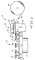
- the apparatus 10 includes an indexing table 12 having a circular top 14 rotatably mounted on a stationary pedestal 16.
- the top 14 is in communication with, for example, a motor (not shown) for rotating the top 14 at a predetermined rate of speed.
- the rate of speed depends on the application.
- a plurality of core plate platforms 18 are rotatably mounted on spindles 20 that are positioned on the top 14 of the indexing table 12.
- Each of the platforms 18 is in communication with, for example, a motor (not shown) for rotating the platforms.
- the apparatus 10 further includes a segment placement station 22 that is positioned in the present embodiment next to the indexing table 12.
- the segment placement station 22 includes a die portion 24 supported by a support member 26.
- the die portion 24 includes an upstream end 28 and a downstream end 30.
- the die portion 24 is moveable in the direction indicated by the arrow 32 shown in Fig. 2.
- the die portion 24 includes a trimming and/or groove cutting area at the upstream end 28 and an end cutting and placement area at the downstream end 30.
- the die portion 24 is in communication with a roll of friction material 34.
- the friction material 34 is preslit to a predetermined width. In the preferred embodiment, the friction material 34 is preslit to a width of three to one inch with a precision width tolerance of ⁇ 0.015 inch.
- the friction material can be conventionally saturated or unsaturated depending on the application.
- the roll of friction material 34 is positioned on a conventional continuous motion dereeler (not shown) with a strip of the friction material 34 being feed into the die portion 24 by first and second guided pinch feed rolls 36 and 38.
- the pinch feed rolls 36 and 38 cooperate to pinch the friction material 34 and push feed the material through the die portion 24 in the direction indicated by the arrow 40 in Fig. 2.
- no feed progression holes are used with the feed length being determined by the pinch feed rolls that are servo driven and controlled to ⁇ 0.001 inch accuracy for the desired length of feed.
- apparatus 10 is an example of a particular type of apparatus that can be utilized to practice the present method.
- Other types of apparatus can be used to practice the present method, such as an inline array apparatus.
- a core plate 42 which has been conventionally preglued on at least one side with a thin layer of phenolic adhesive 43 , is moved in the direction indicated by the arrow 44 shown in Fig. 1 onto a platform 18 of the indexing table 12.
- the top 14 of the indexing table 12 is rotated in the direction indicated by the arrow 46 shown in Fig. 1. This rotation positions the platform 18 and thus the core plate 42 adjacent the downstream end 30 of the die portion 24 of the segment placement station 22.
- the first and second pinch feed rolls 36 and 38 cooperate to feed the friction material into the upstream end 28 of the die portion 24 at a predetermined speed and distance depending on the application.
- the friction material 34 then travels toward the downstream end 30 of the die portion 24.
- the die portion 24 can move in the direction indicated by the arrow 32 shown in Fig. 2.
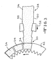
- the upstream end 28 of the die trims the edges 48 and 50 of the friction material 34 as shown in Fig. 3.
- the edges 48 and 50 are trimmed to exact die required width. This width varies with tooling. However, for any given tool the width is fixed to eliminate adjustment.
- the trimmed friction material 34 then travels in the direction indicated by the arrow 52 in Fig. 3 to the downstream end 30 of the die portion 24.
- a segment 54 which is also known as a "keystone segment" is cut from a length of friction material 34.
- the die portion positions the segment 54 on the adhesive 43 of the core plate 42. It should be understood that many adhesive combinations are possible.
- the cutting of the segment 54 is scrapless because the same cut is used on the outside radius of the parted material as used on the inside radius of the next segment to be cut.
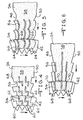
- Flow grooves 56 can be molded or cut in the center 58 of the friction material 34.
- the grooves 56 can have open ends, as shown in Fig. 4, or closed ends, as shown in Fig. 7.
- the closed ends of the grooves 56 can be either on the inside diameter or the outside diameter of the segment 54 depending on the application.
- the grooves 56 can be asymmetrical, straight, or curved depending on the application.
- the segment 54 has three Z-shaped segment portions 60 with two Z-shaped open end grooves 62.
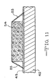
- the present method allows the cut portions' to be completely through the segments 54 down to the core plate 42.
- the cutting of the friction material 34 into segments 54 as described above allows additional effectiveness in either greater oil holding capacity or the same oil holding capacity with greater surface area during use of the core plate 42.
- the same oil capacity groove with greater material mating surface area can be made by cutting a groove to the full material depth to the core plate 42 with a narrower width of cut.
- the platform 18 on which the core plate is positioned rotates in the direction indicated by the arrow 84 shown in Fig. 1.
- a predetermined number of segments 54 are positioned on the core plate. In a preferred embodiment, eight segments 54 are positioned on the core plate 42.
- the top 14 of the indexing table 12 is rotated in the direction indicated by the arrow 46 so that the next core plate is positioned adjacent the downstream end 30 of the die portion 24.
- a completed core plate having multiple segments 54 of friction 34 is moved from the indexing table 12 in the direction indicated by the arrow 86.
- the present method is relatively fast as compared to prior apparatus and methods.
- the method reduces waste of friction material 34. Further, the method provides superior cutting of the friction material 34.
Landscapes
- Engineering & Computer Science (AREA)
- General Engineering & Computer Science (AREA)
- Mechanical Engineering (AREA)
- Braking Arrangements (AREA)
- Mechanical Operated Clutches (AREA)
Claims (11)
- Verfahren zur Herstellung einer Kernplatte, die mehrere Reibmaterialsegmente aufweist, mit den folgenden Schritten:(a) Positionieren einer Kernplatte (42) benachbart zu einem Schneidwerkzeug (24), wobei auf der Kernplatte (42) ein Kleber (43) angeordnet ist und das Schneidwerkzeug (24) mit einer Quelle eines Reibmateriales (34), das Fasern (83) enthält, in Verbindung steht;(b) Zurichten des Reibmateriales (34) zur Anpassung an das Schneidwerkzeug (24) ;(c) Abschneiden eines Vorderrandes (57) des Reibmateriales (34) mit dem Schneidwerkzeug (24), wobei die im Reibmaterial (34) am Vorderrand (57) enthaltenen Fasern (83) in einer Richtung zur Kernplatte (42) hin positioniert werden;(d) Führen des Reibmateriales (34) nach Schritt (c) durch das Schneidwerkzeug (24);(e) Abschneiden eines Hinterrandes (55) des Reibmateriales (34) mit dem Schneidwerkzeug (24) zur Ausbildung eines Segmentes (54), wobei die im Reibmaterial (34) am Hinterrand (55) enthaltenen Fasern (83) in einer Richtung zur Kernplatte (42) hin positioniert werden und wobei mit dem Schritt (e) ein gemeinsamer Schnitt entlang dem Hinterrand (55) eines vorderen Segmentes (54) und dem Vorderrand (57) eines unmittelbar nachfolgenden Segmentes (54) erzeugt wird und die Ausbildung des Segmentes (54) in bezug auf das Reibmaterial (34) im wesentlichen abfallfrei durchgeführt wird;(f) Positionieren des Segementes (54) auf dem Kleber (43) der Kernplatte (42), wodurch die Fasern (83) am Vorderrand (57) und Hinterrand (55) im Kleber (43) angeordnet werden;(g) Drehen der Kernplatte (42); und(h) Wiederholen der Schritte (a) bis (g), bis eine vorgegebene Zahl von Segmenten (54) auf der Kernplatte (42) angeordnet ist.
- Verfahren nach Anspruch 1 bei dem die Quelle des Reibmateriales (34) eine Reibmaterialrolle ist, die auf eine vorgegebene Breite vorgeschnitten worden ist.
- Verfahren nach Anspruch 1, bei dem die Kernplatte (42) auf einer drehbaren Plattform (18) angeordnet wird.
- Verfahren nach Anspruch 3, bei dem die drehbare Plattform (18) auf einer Einrichtung zur Bewegung der Plattform angeordnet wird.
- Verfahren nach Anspruch 1, bei dem das Reibmaterial (34) über mindestens eine geführte Klemmwalze (36, 38) mit einer vorgegebenen Geschwindigkeit und Distanz dem Schneidwerkzeug (24) zugeführt wird.
- Verfahren nach Anspruch 1, bei dem mindestens eine Nut (56) in jedem Segment (54) des Reibmateriales (34) ausgebildet wird, bevor das Segment (54) auf dem Kleber (43) angeordnet wird.
- Verfahren nach Anspruch 6, bei dem die Nut (56) im wesentlichen geradlinig verläuft.
- Verfahren nach Anspruch 6, bei dem die Nut (56) im wesentlichen asymmetrisch ist.
- Verfahren nach Anspruch 6, bei dem die Nut (56) im wesentlichen gekrümmt ist.
- Verfahren nach Anspruch 6, bei dem die Nut (56) offen ist.
- Verfahren nach Anspruch 6, bei dem die Nut (56) geschlossen ist.
Applications Claiming Priority (2)
| Application Number | Priority Date | Filing Date | Title |
|---|---|---|---|
| US08/852,325 US5897737A (en) | 1997-05-07 | 1997-05-07 | Method for making a core plate having multiple friction material segments |
| US852325 | 1997-05-07 |
Publications (3)
| Publication Number | Publication Date |
|---|---|
| EP0878636A2 EP0878636A2 (de) | 1998-11-18 |
| EP0878636A3 EP0878636A3 (de) | 2000-08-16 |
| EP0878636B1 true EP0878636B1 (de) | 2003-01-22 |
Family
ID=25313037
Family Applications (1)
| Application Number | Title | Priority Date | Filing Date |
|---|---|---|---|
| EP98302782A Expired - Lifetime EP0878636B1 (de) | 1997-05-07 | 1998-04-09 | Verfahren zur Herstellung eine Kernplatte mit Multi Reibungsmaterialsegmenten |
Country Status (6)
| Country | Link |
|---|---|
| US (1) | US5897737A (de) |
| EP (1) | EP0878636B1 (de) |
| JP (1) | JP4204094B2 (de) |
| KR (1) | KR100508012B1 (de) |
| CA (1) | CA2233833C (de) |
| DE (1) | DE69810839T2 (de) |
Families Citing this family (42)
| Publication number | Priority date | Publication date | Assignee | Title |
|---|---|---|---|---|
| JP4163283B2 (ja) * | 1998-04-23 | 2008-10-08 | Nskワーナー株式会社 | 摩擦板の製造方法及び装置 |
| JP5133949B2 (ja) * | 1999-05-14 | 2013-01-30 | Nskワーナー株式会社 | 摩擦板の製造方法及び製造装置 |
| JP4514249B2 (ja) * | 1999-05-14 | 2010-07-28 | Nskワーナー株式会社 | 摩擦板の製造方法及び製造装置 |
| JP3643018B2 (ja) | 1999-07-22 | 2005-04-27 | アイシン化工株式会社 | クラッチ用摩擦板の製造方法及び製造装置 |
| JP4297308B2 (ja) * | 2000-04-13 | 2009-07-15 | アイシン化工株式会社 | 湿式摩擦部材 |
| JP3614763B2 (ja) * | 2000-08-02 | 2005-01-26 | 株式会社エフ・シー・シー | 平坦な摩擦面を持つ摩擦板の製造方法,及びその製造装置 |
| AU2002216020A1 (en) * | 2000-12-07 | 2002-06-18 | Mannesmann Sachs Ag | Double or multiple disk coupling device and disk arrangement therefor |
| US6601684B2 (en) | 2001-09-12 | 2003-08-05 | Borgwarner Inc. | Unitary, circumferentially edge wound friction material clutch plate, and method of making same |
| US6668891B2 (en) | 2001-09-12 | 2003-12-30 | Borgwarner Inc. | Unitary, circumferentially edge wound friction material clutch plate, and method of making same |
| US20040099371A1 (en) * | 2002-11-22 | 2004-05-27 | Hardies Tom C. | Multi-segmented friction plate with maximized steel-to-oil surface area for improved thermal capacity |
| JP3971696B2 (ja) * | 2002-12-17 | 2007-09-05 | 株式会社エフ・シー・シー | 湿式クラッチ用摩擦板の製造方法 |
| US6790308B2 (en) | 2003-01-03 | 2004-09-14 | Borgwarner Inc. | Method and apparatus for making clutch plate with multi segment friction material |
| US7014024B2 (en) | 2003-06-11 | 2006-03-21 | Sulzer Euroflamm Us Inc. | System and method for improving cooling in a friction facing environment |
| US7014027B2 (en) * | 2003-07-14 | 2006-03-21 | Borgwarner Inc. | Friction material having oil localization slots |
| WO2005033539A1 (en) * | 2003-09-23 | 2005-04-14 | Gilman Engineering & Manufacturing Co. Llc | Assembly process for scrapless clutch plate assembly |
| US6991668B2 (en) | 2003-09-26 | 2006-01-31 | Towsley Frank E | Diesel soot filter |
| US7168544B2 (en) * | 2003-10-02 | 2007-01-30 | Sulzer Euroflamm Us Inc. | Friction facing material for use in a friction environment |
| US20060236523A1 (en) * | 2003-10-02 | 2006-10-26 | Sulzer Euroflamm Us Inc | Friction facing method for use in a friction environment |
| US20050075021A1 (en) * | 2003-10-03 | 2005-04-07 | Lam Robert C. | High performance, durable, deposit friction material |
| US20050074595A1 (en) * | 2003-10-03 | 2005-04-07 | Lam Robert C. | Friction material containing partially carbonized carbon fibers |
| US7113865B2 (en) * | 2003-12-15 | 2006-09-26 | Ignatin Gary R | Roadway travel data exchange network |
| JP3971745B2 (ja) * | 2003-12-22 | 2007-09-05 | 株式会社エフ・シー・シー | クラッチ用摩擦板の製造方法および装置 |
| US8021744B2 (en) * | 2004-06-18 | 2011-09-20 | Borgwarner Inc. | Fully fibrous structure friction material |
| US7429418B2 (en) | 2004-07-26 | 2008-09-30 | Borgwarner, Inc. | Porous friction material comprising nanoparticles of friction modifying material |
| US8603614B2 (en) | 2004-07-26 | 2013-12-10 | Borgwarner Inc. | Porous friction material with nanoparticles of friction modifying material |
| JP4503416B2 (ja) * | 2004-10-28 | 2010-07-14 | Nskワーナー株式会社 | 湿式摩擦板の製造方法 |
| US7806975B2 (en) * | 2005-04-26 | 2010-10-05 | Borgwarner Inc. | Friction material |
| US9951826B2 (en) * | 2005-11-01 | 2018-04-24 | Borgwarner Inc. | Segmented and laminated core steel plate for single and/or double sided wet clutch friction plates or separator plates |
| US8394452B2 (en) * | 2005-11-02 | 2013-03-12 | Borgwarner Inc. | Carbon friction materials |
| CN101375075B (zh) | 2006-02-21 | 2011-05-18 | 博格华纳公司 | 分段式芯片和摩擦盘 |
| US20070270069A1 (en) * | 2006-05-18 | 2007-11-22 | Sulzer Euroflamm Us Inc. | Friction material and system and method for making the friction material |
| JP4523616B2 (ja) * | 2007-03-28 | 2010-08-11 | 株式会社エフ・シー・シー | 湿式クラッチ用摩擦板及びその製造方法 |
| EP2028221A1 (de) * | 2007-08-03 | 2009-02-25 | Borgwarner, Inc. | Reibungsmaterial mit Silicium |
| DE102008013907B4 (de) | 2008-03-12 | 2016-03-10 | Borgwarner Inc. | Reibschlüssig arbeitende Vorrichtung mit mindestens einer Reiblamelle |
| DE102009030506A1 (de) * | 2008-06-30 | 2009-12-31 | Borgwarner Inc., Auburn Hills | Reibungsmaterialien |
| AT507251B1 (de) | 2008-09-05 | 2018-03-15 | Miba Frictec Gmbh | Reiblamelle |
| DE102009048377B4 (de) * | 2009-10-06 | 2011-09-01 | Getrag Ford Transmissions Gmbh | Verfahren zum Herstellen von Lamellen einer Reibkupplung |
| EP2384694A1 (de) | 2010-05-05 | 2011-11-09 | Roche Diagnostics GmbH | Verfahren zur Herstellung eines Membranrings oder Teststreifenrings |
| US9943938B2 (en) | 2011-12-09 | 2018-04-17 | Borgwarner Inc. | Method and apparatus for making a friction plate |
| US9631689B2 (en) * | 2012-10-02 | 2017-04-25 | Schaeffler Technologies AG & Co. KG | Method and installation for applying friction lining elements to a friction lining support |
| US11286993B2 (en) | 2018-07-24 | 2022-03-29 | Borgwarner Inc. | Segmented and laminated one-way clutch components |
| KR102918312B1 (ko) * | 2023-10-11 | 2026-01-28 | (주)삼성정밀 | 브레이크 슈 어셈블리 제조방법 |
Family Cites Families (12)
| Publication number | Priority date | Publication date | Assignee | Title |
|---|---|---|---|---|
| US30528A (en) * | 1860-10-30 | Machine fob | ||
| USRE30528E (en) | 1973-09-07 | 1981-02-24 | Haggar Company | Method of and apparatus for making bonded belt loops |
| US4260047A (en) * | 1979-12-03 | 1981-04-07 | General Motors Corporation | Friction disc and method of making same |
| EP0180389B1 (de) * | 1984-10-26 | 1990-02-07 | Brake And Clutch Industries Australia Pty. Ltd. | Reibungselemente für Kupplungsplatten und dergleichen |
| US4878282A (en) * | 1987-09-04 | 1989-11-07 | Borg-Warner Automotive Gmbh | Method for the production of friction plates, synchronizing blocker rings or similar structures |
| US5094331A (en) * | 1988-03-18 | 1992-03-10 | Honda Giken Kogyo Kabushiki Kaisha | Wet-type multiplate clutch |
| JP2664526B2 (ja) * | 1990-07-10 | 1997-10-15 | 三洋電機株式会社 | 自動販売機 |
| US5176236A (en) * | 1992-01-09 | 1993-01-05 | Borg-Warner Automotive Transmission & Engine Components Corporation | Facing material for wet clutch plate and methods for fabricating and applying same |
| US5571372A (en) * | 1992-07-21 | 1996-11-05 | Kabushiki Kaisha F.C.C. | Process and apparatus for manufacturing clutch friction plate |
| EP0583516B1 (de) * | 1992-08-06 | 1996-07-17 | Kabushiki Kaisha F.C.C. | Verfahren und Vorrichtung zum Herstellen von Kupplungsreibscheiben |
| US5460255A (en) * | 1993-03-25 | 1995-10-24 | Borg-Warner Automotive, Inc. | Universal segmented friction clutch facing |
| AT401806B (de) * | 1995-07-25 | 1996-12-27 | Miba Frictec Gmbh | Verfahren zum herstellen eines ebenen reibringes |
-
1997
- 1997-05-07 US US08/852,325 patent/US5897737A/en not_active Expired - Lifetime
-
1998
- 1998-04-01 CA CA002233833A patent/CA2233833C/en not_active Expired - Fee Related
- 1998-04-09 EP EP98302782A patent/EP0878636B1/de not_active Expired - Lifetime
- 1998-04-09 DE DE69810839T patent/DE69810839T2/de not_active Expired - Lifetime
- 1998-04-22 KR KR10-1998-0014385A patent/KR100508012B1/ko not_active Expired - Lifetime
- 1998-04-30 JP JP12017998A patent/JP4204094B2/ja not_active Expired - Lifetime
Also Published As
| Publication number | Publication date |
|---|---|
| DE69810839D1 (de) | 2003-02-27 |
| EP0878636A3 (de) | 2000-08-16 |
| EP0878636A2 (de) | 1998-11-18 |
| KR19980086635A (ko) | 1998-12-05 |
| KR100508012B1 (ko) | 2005-11-11 |
| CA2233833C (en) | 2006-07-18 |
| DE69810839T2 (de) | 2003-06-05 |
| JPH10318309A (ja) | 1998-12-04 |
| JP4204094B2 (ja) | 2009-01-07 |
| CA2233833A1 (en) | 1998-11-07 |
| US5897737A (en) | 1999-04-27 |
Similar Documents
| Publication | Publication Date | Title |
|---|---|---|
| CA2233833C (en) | Method for making a core plate having multiple friction material segments | |
| US5338382A (en) | Fabrication of pile weatherstripping having fins | |
| US5609075A (en) | Razor blade manufacture | |
| US4851067A (en) | Method for producing a weather strip for an automobile | |
| US7434300B2 (en) | Process and device for producing clutch friction plate | |
| US6596119B2 (en) | Manufacturing method of friction plate for clutch | |
| EP0486533A1 (de) | Vorrichtung zur herstellung seitlicher ausschnitte aus laufenden bahnen. | |
| US5093971A (en) | Method and apparatus for forming expanded mesh battery grid and grid formed therefrom | |
| US4517872A (en) | Controlled depth cutting method and apparatus | |
| US6036903A (en) | Method of making an annular friction liner | |
| US6367302B1 (en) | Method for bending and cutting metal strip material | |
| US7998297B2 (en) | Tire structural member fabricating method and apparatus for carrying out the same | |
| JPS6239708Y2 (de) | ||
| US4604011A (en) | Method and apparatus for edge-planing sheet metal | |
| US4963126A (en) | Method and apparatus for forming carton blanks | |
| EP0750535B1 (de) | Rasierklingenherstellung | |
| US4997323A (en) | Edge finished resilient tile, method and apparatus | |
| US4523364A (en) | High speed production of multiple gauge strip | |
| US4431141A (en) | Method of making a roll paper product | |
| KR20010092310A (ko) | 두 외층 사이에 경질 발포 코어가 배치된 연속 제조 압출패널로부터 한정된 길이의 구획을 제거하는 방법 및 톱질장치 | |
| SI20041A (sl) | Postopek zlaganja večslojnih pasivnih elektronskih komponent | |
| CN223763481U (zh) | 一种用于岩棉板的修整设备 | |
| JPS63317304A (ja) | グリ−ンシ−トの製造方法 | |
| US5471971A (en) | Turret tile and machine for production of turret tile | |
| JPH06285572A (ja) | 長尺異形断面板の加工装置 |
Legal Events
| Date | Code | Title | Description |
|---|---|---|---|
| PUAI | Public reference made under article 153(3) epc to a published international application that has entered the european phase |
Free format text: ORIGINAL CODE: 0009012 |
|
| AK | Designated contracting states |
Kind code of ref document: A2 Designated state(s): DE FR |
|
| AX | Request for extension of the european patent |
Free format text: AL;LT;LV;MK;RO;SI |
|
| PUAL | Search report despatched |
Free format text: ORIGINAL CODE: 0009013 |
|
| AK | Designated contracting states |
Kind code of ref document: A3 Designated state(s): AT BE CH CY DE DK ES FI FR GB GR IE IT LI LU MC NL PT SE |
|
| AX | Request for extension of the european patent |
Free format text: AL;LT;LV;MK;RO;SI |
|
| 17P | Request for examination filed |
Effective date: 20010206 |
|
| AKX | Designation fees paid |
Free format text: DE FR |
|
| 17Q | First examination report despatched |
Effective date: 20020103 |
|
| GRAG | Despatch of communication of intention to grant |
Free format text: ORIGINAL CODE: EPIDOS AGRA |
|
| GRAG | Despatch of communication of intention to grant |
Free format text: ORIGINAL CODE: EPIDOS AGRA |
|
| GRAH | Despatch of communication of intention to grant a patent |
Free format text: ORIGINAL CODE: EPIDOS IGRA |
|
| RAP1 | Party data changed (applicant data changed or rights of an application transferred) |
Owner name: BORGWARNER INC. |
|
| GRAH | Despatch of communication of intention to grant a patent |
Free format text: ORIGINAL CODE: EPIDOS IGRA |
|
| GRAA | (expected) grant |
Free format text: ORIGINAL CODE: 0009210 |
|
| AK | Designated contracting states |
Kind code of ref document: B1 Designated state(s): DE FR |
|
| REF | Corresponds to: |
Ref document number: 69810839 Country of ref document: DE Date of ref document: 20030227 Kind code of ref document: P |
|
| ET | Fr: translation filed | ||
| PLBE | No opposition filed within time limit |
Free format text: ORIGINAL CODE: 0009261 |
|
| STAA | Information on the status of an ep patent application or granted ep patent |
Free format text: STATUS: NO OPPOSITION FILED WITHIN TIME LIMIT |
|
| 26N | No opposition filed |
Effective date: 20031023 |
|
| REG | Reference to a national code |
Ref country code: FR Ref legal event code: PLFP Year of fee payment: 19 |
|
| REG | Reference to a national code |
Ref country code: FR Ref legal event code: PLFP Year of fee payment: 20 |
|
| PGFP | Annual fee paid to national office [announced via postgrant information from national office to epo] |
Ref country code: FR Payment date: 20170322 Year of fee payment: 20 |
|
| PGFP | Annual fee paid to national office [announced via postgrant information from national office to epo] |
Ref country code: DE Payment date: 20170428 Year of fee payment: 20 |
|
| REG | Reference to a national code |
Ref country code: DE Ref legal event code: R071 Ref document number: 69810839 Country of ref document: DE |