EP0878158B1 - Brühgerät für Kaffee mit einer feinporigen Schaumschicht - Google Patents
Brühgerät für Kaffee mit einer feinporigen Schaumschicht Download PDFInfo
- Publication number
- EP0878158B1 EP0878158B1 EP98201517A EP98201517A EP0878158B1 EP 0878158 B1 EP0878158 B1 EP 0878158B1 EP 98201517 A EP98201517 A EP 98201517A EP 98201517 A EP98201517 A EP 98201517A EP 0878158 B1 EP0878158 B1 EP 0878158B1
- Authority
- EP
- European Patent Office
- Prior art keywords
- buffer reservoir
- coffee extract
- liquid
- opening
- coffee
- Prior art date
- Legal status (The legal status is an assumption and is not a legal conclusion. Google has not performed a legal analysis and makes no representation as to the accuracy of the status listed.)
- Expired - Lifetime
Links
Images


Classifications
-
- A—HUMAN NECESSITIES
- A47—FURNITURE; DOMESTIC ARTICLES OR APPLIANCES; COFFEE MILLS; SPICE MILLS; SUCTION CLEANERS IN GENERAL
- A47J—KITCHEN EQUIPMENT; COFFEE MILLS; SPICE MILLS; APPARATUS FOR MAKING BEVERAGES
- A47J31/00—Apparatus for making beverages
- A47J31/24—Coffee-making apparatus in which hot water is passed through the filter under pressure, i.e. in which the coffee grounds are extracted under pressure
- A47J31/30—Coffee-making apparatus in which hot water is passed through the filter under pressure, i.e. in which the coffee grounds are extracted under pressure with hot water under steam pressure
-
- A—HUMAN NECESSITIES
- A47—FURNITURE; DOMESTIC ARTICLES OR APPLIANCES; COFFEE MILLS; SPICE MILLS; SUCTION CLEANERS IN GENERAL
- A47J—KITCHEN EQUIPMENT; COFFEE MILLS; SPICE MILLS; APPARATUS FOR MAKING BEVERAGES
- A47J31/00—Apparatus for making beverages
- A47J31/44—Parts or details or accessories of beverage-making apparatus
- A47J31/4496—Means to produce beverage with a layer on top, e.g. of cream, foam or froth
-
- A—HUMAN NECESSITIES
- A47—FURNITURE; DOMESTIC ARTICLES OR APPLIANCES; COFFEE MILLS; SPICE MILLS; SUCTION CLEANERS IN GENERAL
- A47J—KITCHEN EQUIPMENT; COFFEE MILLS; SPICE MILLS; APPARATUS FOR MAKING BEVERAGES
- A47J31/00—Apparatus for making beverages
- A47J31/44—Parts or details or accessories of beverage-making apparatus
- A47J31/46—Dispensing spouts, pumps, drain valves or like liquid transporting devices
- A47J31/462—Dispensing spouts, pumps, drain valves or like liquid transporting devices with an intermediate liquid storage tank
- A47J31/465—Dispensing spouts, pumps, drain valves or like liquid transporting devices with an intermediate liquid storage tank for the heated water
-
- A—HUMAN NECESSITIES
- A47—FURNITURE; DOMESTIC ARTICLES OR APPLIANCES; COFFEE MILLS; SPICE MILLS; SUCTION CLEANERS IN GENERAL
- A47J—KITCHEN EQUIPMENT; COFFEE MILLS; SPICE MILLS; APPARATUS FOR MAKING BEVERAGES
- A47J31/00—Apparatus for making beverages
- A47J31/44—Parts or details or accessories of beverage-making apparatus
- A47J31/46—Dispensing spouts, pumps, drain valves or like liquid transporting devices
- A47J31/462—Dispensing spouts, pumps, drain valves or like liquid transporting devices with an intermediate liquid storage tank
- A47J31/467—Dispensing spouts, pumps, drain valves or like liquid transporting devices with an intermediate liquid storage tank for the infusion
Definitions
- the invention relates to an apparatus for preparing coffee extract having a small-bubbled foam layer, comprising at least one inlet for coffee extract and at least one outflow opening for discharging coffee extract having a small-bubbled foam layer, the inlet being provided with at least one spout opening for generating a coffee extract liquid jet when coffee extract is fed to the inlet.
- Such apparatus is inter alia known from international patent application WO 95/16377.
- a small-bubbled foam layer is obtained by the increased speed of the liquid jet.
- the liquid flows directly from the outlet to the outflow opening.
- the character of the small-bubbled foam layer obtained i.e. the distribution of the size of the different bubbles, proves to be little uniform and predictable.
- it is also known to provide the outflow opening, rather than the inlet, with a spout opening. Accordingly, the apparatus spouts directly into, for instance, a cup.
- this variant also has the above-outlined drawbacks.
- the object of the invention is to meet these problems and is characterized in that, in the liquid flow path extending between the spout opening and the outflow opening, a buffer reservoir is incorporated, spaced from the spout opening and the outflow opening, the buffer reservoir being positioned such that, in use, the coffee extract liquid jet from the spout opening spouts into a liquid surface of coffee extract already received in the buffer reservoir.
- the spout opening of the inlet generates a coffee extract jet.
- This coffee extract jet ends up in the buffer reservoir, so that the buffer reservoir will be filled with a quantity of coffee extract. Due to the fact that the coffee extract jet spouts into the liquid surface of the meanwhile filled buffer reservoir, bubbles will be formed in the buffer reservoir. At the same time, at least a portion of the coffee extract having bubbles will flow from the buffer reservoir to subsequently flow from the apparatus via the outflow opening. Since the liquid jet spouts into the buffer reservoir, a small-bubbled foam layer is obtained whose properties are predetermined.
- the apparatus is connected to a high-pressure coffee apparatus.
- the coffee apparatus feeds hot water to the coffee filter in the apparatus.
- the coffee filter In the coffee filter, the ground coffee is compressed to form a compact whole.
- the coffee extract is forced out via the openings in the bottom of the coffee filter.
- bubbles are formed in a space between the bottom of the coffee filter and the top wall of the spherical cover. Bubbles smaller than the section of the orifices of the spherical cover can then flow away from the apparatus via the outflow openings in the bottom.
- a coffee extract is dispensed which can be received in a cup disposed under the assembly.
- a foam layer will be present on the coffee extract.
- a drawback of the assembly known from Gebrauchsmuster 29502575 is that for forming the bubbles, it is necessary to build up a high pressure in the apparatus. This implies that for pressurizing the apparatus, relatively expensive means, such as an electric pump, are required.
- the object of the invention is to provide an apparatus whereby a coffee extract having a small-bubbled foam layer can also be prepared under low pressure.
- the flowing away of coffee extract with bubbles from the buffer reservoir can for instance be effected in that the buffer reservoir overflows.
- the buffer reservoir is provided with at least one run-out opening for discharging coffee extract with a small-bubbled foam layer from the buffer reservoir to the outflow opening. This has the advantage that after the preparation of the coffee extract having a small-bubbled foam layer, no or only little residual liquid stays behind in the buffer reservoir.
- the buffer reservoir is of bowl-shaped design, with the run-out opening provided in a sidewall of the buffer reservoir.
- the buffer reservoir is of bowl-shaped design while a bottom of the buffer reservoir is provided with at least one run-out opening for discharging coffee extract having a small-bubbled foam layer from the buffer reservoir to the outflow opening.
- the apparatus is characterized in that a buffer reservoir is incorporated into the liquid flow path extending between the spout opening and the outflow opening, said buffer reservoir being spaced from the spout opening and comprising said outflow opening, while, in use, the buffer reservoir is positioned such that, in use, the coffee extract liquid jet from the spout opening spouts into a liquid surface of coffee extract already received in the buffer reservoir, and the quantity of coffee extract dispensed through the spout opening per unit of time on the one hand and the quantity of coffee extract flowing from the buffer reservoir via the outflow opening per unit of time on the other hand are adjusted to each other so that in the
- the jet striking the bath involves the formation of a small-bubbled foam layer. Via the outflow openings, this small-bubbled foam layer is entrained with the rest of the coffee extract to subsequently flow into a container.
- the quantity of coffee extract dispensed through the spout opening per unit of time and the quantity of coffee extract flowing via the outflow opening from the buffer reservoir per unit of time are adjusted to each other so that in the buffer reservoir a liquid surface is formed having a height of at least 8 mm.
- the apparatus further comprises a moka unit for preparing the coffee extract, the moka unit being in fluid connection with the inlet.
- the moka unit has the characteristic feature of dispensing a coffee extract under a relatively low pressure of, for instance, 0.4 atmosphere. In combination with the spout opening of the inlet and the buffer reservoir, this low pressure is sufficient for obtaining a coffee extract having a small-bubbled foam layer.
- the moka unit preferably comprises a hermetically closable liquid container, a coffee container that can be filled with ground coffee, a liquid-conveying tube connected on one side to the coffee container and comprising on the other side an open end located adjacent a bottom of the liquid container, the inlet with the spout opening being in fluid connection with the coffee container such that, in use, the ground coffee is located in the liquid flow path from the liquid container to the inlet.
- the liquid container comprises means for controlling the ratio between the quantities of liquid and air in the liquid container without changing the quantity of liquid for setting the temperature of the liquid which, in use, is fed to the coffee container.
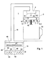
- reference numeral 1 designates an apparatus according to the invention for preparing coffee extract having a small-bubbled foam layer.
- the apparatus comprises a housing 2 with an inlet 4 to which, in use, coffee extract is fed.
- the housing 2 further comprises at least one outflow opening.
- the housing comprises two relatively large outflow openings 6.1 and 6.2.
- the inlet 2 is provided with two relatively small spout openings 8.1 and 8.2. Further, between the spout openings 8.1 and 8.2 on one side and the outflow openings 6.1 and 6.2 on the other, a buffer reservoir 10 is present, spaced from the spout openings 8.1, 8.2 and the outflow openings 6.1 and 6.2.
- the buffer reservoir 10 is incorporated into the liquid flow path extending between the spout openings 8.1 and 8.2 on one side and the outflow openings 6.1 and 6.2 on the other. Between the buffer reservoir and the outflow openings 6.1 and 6.2, an interspace 15 is present.
- the buffer reservoir 10 is of bowl-shaped design and has a flat bottom 12 with vertical sidewalls 14. Between the bottom 12 of the buffer reservoir and the outflow opening, the interspace 15 is present. Also, an interspace 17 is present between the spout openings 8.1 and 8.2 on one side and the buffer reservoir on the other.
- the apparatus of Fig. 1 further comprises a moka unit 19, to be discussed in more detail hereinbelow, which feeds coffee extract via line 18 to the inlet 4 under a relatively low pressure of, for instance, 0.4 atmosphere.
- a moka unit 19 to be discussed in more detail hereinbelow, which feeds coffee extract via line 18 to the inlet 4 under a relatively low pressure of, for instance, 0.4 atmosphere.
- each of the spout openings 8.1 and 8.2 is for instance equal to 0.05-0.5 mm 2 .
- the jets of coffee extract spout downwards into the buffer reservoir 10. This buffer reservoir 10 will be filled with the coffee extract.
- the coffee extract jets spout with force into the liquid surface of the buffer reservoir 10.
- This coffee extract is also known by the name of 'café crème'.
- the container 20 may consist of a cup or a coffeepot.
- the section of the outflow openings 6.1 and 6.2 is selected so that café crème with the desired bubble size in the small-bubbled foam layer can flow from the housing 2 without the bubbles disappearing.
- the outflow openings 6.1, 6.2 are larger than the desired maximal size of the bubbles in the foam layer.
- the container 20 After the container 20 has been filled with coffee, it can be removed for consumption. In the buffer reservoir, a residual liquid will stay behind, because the buffer reservoir is filled up to the top ends of the vertical sidewalls 14.
- the buffer reservoir 10 is provided with at least one run-out path 22 for discharging coffee extract having a small-bubbled foam layer from the buffer reservoir to the outflow opening.
- Fig. 3 is a top plan view of the buffer reservoir 10 according to Fig. 1 comprising such run-out path 22.
- the run-out path 22 comprises an opening 24 in the vertical sidewall, extending upwards from the bottom 12 of the buffer reservoir 10. This enables the buffer reservoir 10 to drain completely. To ensure that the buffer reservoir 10 does not drain too quickly, so that, in the period when the coffee extract jets spout into the buffer reservoir, a liquid surface can be built up in the buffer reservoir, the run-out path is provided with a predetermined flow resistance 26.
- the flow resistance 26 is formed by a channel formed by vertical sidewalls in the buffer reservoir, with an inlet located in the buffer reservoir and an outlet coinciding with the opening 24 in the vertical sidewall 14 of the buffer reservoir 10.
- the vertical sidewalls 28 of the flow resistance 26 are equally high as the vertical sidewalls 14 of the buffer reservoir 10.
- the channel formed by the vertical sidewalls 28 is of a slightly meandering design, to increase the flow resistance.
- Fig. 4 again shows the buffer reservoir 10, which, however, now comprises an alternative run-out path 22'.
- the buffer reservoir accordingly comprises an opening 30 provided in the bottom 12.
- a vertical sidewall 32 having an opening 34 extending upwards from the bottom 12.
- the vertical sidewall 32 encloses the opening 30 partially.
- a circular, vertical sidewall 36 also having an opening 38 extending upwards from the bottom 12.
- the vertical sidewall 36 also encloses the opening 30 partially.
- the run-out path 22' extends from the opening 38 to the opening 30 via the circular channel formed between the vertical sidewalls 32 and 36 and via the opening 34.
- the two vertical sidewalls 32 and 36 are equally high and the openings 34 and 38 are located on both sides of the opening 30.
- the vertical sidewalls 32 and 36 are absent, so that only the opening 30 remains. It is also possible that at least one of the vertical sidewalls 32, 36 encloses the opening 30 entirely, so that at least one of the openings 34, 38 is absent.
- the great advantage of the assembly of the inlet 4, the outflow openings 6.1 and 6.2, and the buffer reservoir 10 is that coffee extract having a small-bubbled foam layer can be obtained while coffee extract is fed to the inlet 4 under relatively low pressure.
- the distance between the spout opening and the buffer reservoir is of settable design.
- This can for instance be realized by attaching the buffer reservoir to the housing 2 by means of a spindle 40.
- the housing 2 is provided with an opening having screw thread, which opening having screw thread corresponds to the screw thread of the spindle 40.
- the distance mentioned can be varied.
- the nature of the small-bubbled foam layer formed can be set.
- the size of the bubbles thus proves to be connected with the distance mentioned.
- the distance between the outflow opening and the buffer reservoir is settable as well, while the distance between the spout openings and the outflow openings is fixed.
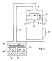
- the moka unit 19 of Figs. 1 and 5 comprises a hermetically closable liquid container 44, a coffee container 46 which can be filled with ground coffee 47, and a liquid-conveying tube 48 which is on one side connected to the coffee container 46 and on the other side comprises an open end 52 located adjacent a bottom 50 of the liquid container 44.
- the conveying tube 48 acts as a riser.
- the inlet is in fluid connection with the coffee container 46.
- the ground coffee present in the coffee container will be located in the liquid flow path from the liquid container 44 to the inlet 4.
- the liquid container is filled with water and hermetically closed with the cover-shaped coffee container 46.
- the water level 53 is shown schematically.
- the apparatus further comprises means 54 for controlling the ratio between the quantities of liquid and air in the liquid container 44.
- the liquid container 44 is heated. Heating can be performed with means known per se, such as a flame or an electric heating element. Through heating, the pressure in the liquid container 44 will increase. When the pressure has sufficiently increased, the liquid will be forced upwards through the conveying tube 48. The liquid then flows via the conveying tube 48 through the coffee container 46 filled with ground coffee, to subsequently leave the coffee container as coffee extract and flow, via the line 18, to the inlet 4.
- Heating can be performed with means known per se, such as a flame or an electric heating element.
- the pressure in the liquid container 44 will increase. When the pressure has sufficiently increased, the liquid will be forced upwards through the conveying tube 48. The liquid then flows via the conveying tube 48 through the coffee container 46 filled with ground coffee, to subsequently leave the coffee container as coffee extract and flow, via the line 18, to the inlet 4.
- the initial temperature at which the water starts leaving the liquid container 44 via the conveying tube 48 can be controlled by setting the liquid/water ratio in the liquid container 44, without changing the quantity of water. If it is assumed that the filling height of the liquid container 44 will in each case be approximately the same, this ratio can for instance be set by means of bodies 54 disposed in the liquid container, which are immersed in the liquid. These bodies 54 displace a predetermined quantity of liquid. In the period when the water leaves the moka unit 19, the air/water ratio will further increase and the temperature of the water leaving the moka unit 19 will likewise increase.
- the temperature i.e. the variation in temperature of the liquid fed to the coffee container 46, can be controlled in this manner.
- the air/water ratio can also be controlled by varying the quantity of water with which the liquid container 46 is filled.
- the quantity of ground coffee included in the coffee container 46 can for instance be contained in a sachet, the sachet being placed in the coffee container.
- the manner in which the ground coffee is positioned in the coffee container is not relevant to the present invention.
- the coffee container 46 forms a part of the moka unit.
- the coffee container and the liquid container are integrated into one housing.
- the conveying tube 48 is connected to the coffee container 46 via line 18.
- the coffee container 46 may comprise a cover that can be unscrewed (not shown).
- a one-cup filter 56 known per se is included in the coffee container 46. It is also possible (Fig.
- a beaker-shaped filter casing known per se, filled with coffee.
- the filter casing has its bottom side provided with a number of very small orifices which are on the one hand permeable to liquid and on the other form a barrier to the ground coffee contained in the filter casing.
- a top wall 58 of the water container 16 of the moka unit is connected to vertical sidewalls 60 of the water container such that the distance D between the top wall 58 and the bottom 62 is of settable design. With this, the air/water ratio can again be controlled.
- the air/water ratio can also be adjusted during a period in which the water flows from the liquid container. Hence, this permits the temperature of the water leaving the liquid container to be controlled or set at any moment.
- the air/water ratio can then for instance be maintained constant at a predetermined value throughout the period in which the water flows from the liquid container. The above can be realized by readjusting the height D during the period in which the water leaves the moka unit 19 of Fig. 2.
- Fig. 5 shows a third possible embodiment of an apparatus according to the invention.
- parts corresponding to Figs. 1 and 2 are provided with identical reference numerals.
- the buffer reservoir is formed by the housing 2, while the moka unit corresponds to the moka unit of Fig. 1.
- a bottom 64 of the housing 2 constitutes the bottom of the buffer reservoir 10.
- the outflow openings 6.1 and 6.2 are provided in the bottom 64 of the buffer reservoir 10.
- the quantity of coffee extract dispensed through the spout openings 8.1 and 8.2 per unit of time and the quantity of coffee extract flowing from the buffer reservoir via the outflow openings 6.1 and 6.2 per unit of time are adjusted to each other so that in the buffer reservoir, a liquid surface 66 is formed having a height h of at least 5 mm.
- the coffee extract contained in the liquid reservoir 10 will leave the buffer reservoir via the outflow openings 6.1 and 6.2. This will involve the formed bubbles leaving the buffer reservoir as well.
- the small-bubbled foam layer is as it were entrained with the coffee extract.
- the height of the liquid surface formed is in particular less than 25 mm. Preferably, this height is less than 15 mm.
- the height h is at least equal to 8 mm, in order that the coffee extract jets can strike the liquid bath, located in the buffer reservoir, over a distance of at least 8 mm.
- the impact over this height of at least 8 mm results in the formation of many bubbles of a uniform character.
- FIG. 6 a fourth possible embodiment of an apparatus according to the invention is shown.
- parts corresponding to the previous Figures are again provided with identical reference numerals.
- the apparatus according to Figs. 6-9 is provided with an alternative embodiment of the housing 2 with accessories, and with an alternative embodiment of the moka unit 19.
- the buffer reservoir 10 now comprises first and second run-out paths 22.1 and 22.2.
- the first run-out path 22.1 comprises an opening 24.1 provided in the vertical sidewall 14 of the buffer reservoir 10.
- the first opening 24.1 extends from a top side of the vertical sidewall 14 in the direction of the bottom 12. However, the opening 24.1 does not reach the bottom 12.
- the second run-out path 22.2 comprises a second opening 24.2.
- the second opening 24.2 separated from the first opening 24.1 is designed in the same manner as the first opening 24.1.
- a partition 70 is provided which divides the space within the housing 2 yet outside the buffer reservoir 10 into two separate parts 72.1 and 72.2 respectively, the arrangement being such that the outflow opening 6.1 is in fluid connection with the first part 72.1 of the housing 2. Further, the outflow opening 6.2 is in fluid connection with the second part 72.2 of the housing 2. Further provided in the bottom 12 of the buffer reservoir 10 are a first and a second opening 30.1 and 30.2. The first opening 30.1 forms a fluid connection between the inside of the buffer reservoir 10 and the first part 72.1 of the housing 2. Further, the opening 30.2 provides a fluid connection between the inside of the buffer reservoir 10 and the second part 72.2 of the housing 2.
- the moka unit 19 feeds coffee extract to the inlet 4 via the line 18, this liquid will be spouted, via the spout openings 8.1 and 8.2, into the buffer reservoir 10, as already discussed hereinabove in relation to the previous Figures.
- the openings 30.1 and 30.2 have such dimensions that per second, more coffee extract is fed to the buffer reservoir via the spout openings 8.1 and 8.2 than is discharged via these openings 30.1 and 30.2.
- the liquid level in the buffer reservoir 10 starts to rise and due to the spouting of the coffee extract into the thus formed liquid surface, a small-bubbled foam layer is formed having a height of, for instance, at least 8 mm.
- the level in the buffer reservoir 10 will eventually increase up to the bottom side of the openings 24.1 and 24.2. After this, the coffee extract with the small-bubbled foam layer will flow, via the opening 24.1, to the portion 72.1 of the container. At the same time, via the opening 24.2, the coffee extract with the small-bubbled foam layer will flow to the portion 72.2 of the container 2.
- the liquids leaving the buffer reservoir 10 via the openings 24.1 and 24.2 remain separated from each other. Consequently, by the buffer reservoir 10, two separate flows of liquid are developed.
- the liquid flowing from the opening 24.1 will eventually leave the container 2 via the outflow opening 6.1. Further, the liquid flowing from the opening 24.2 will leave the container 2 via the outflow opening 6.2.
- two containers 20.1 and 20.2 can be filled with coffee extract.
- a great advantage of the above-discussed embodiment is that the two containers 20.1 and 20.2 will be filled very accurately and to an equal extent with coffee extract having a small-bubbled foam layer.
- the buffer reservoir 10 drains via the openings 30.1 and 30.2.
- the liquid leaving the buffer reservoir 10 via the opening 30.1 will end up in the container 20.1 via the outflow opening 6.1.
- the liquid leaving the buffer reservoir 10 via the opening 30.2 will end up in the container 20.2 via the outflow opening 6.2.
- the apparatus is hence provided with the first and second outflow openings which are positioned relative to the first and second run-out paths so that the buffer reservoir comprises a first and a second run-out path for discharging coffee extract from the buffer reservoir, and that the apparatus is provided with a first and a second outflow opening which are positioned relative to the first and second run-out paths so that the coffee extract with the small-bubbled foam layer leaving the buffer reservoir via the first run-out path is fed to the first outflow opening, and the coffee extract with the small-bubbled foam layer leaving the buffer reservoir via the second run-out path is fed to the second outflow opening.
- Figs. 6-9 is also provided with a particular embodiment of a moka unit 19.
- the moka unit 19 comprises a liquid container 44.
- the liquid container 44 comprises a bowl-shaped container 72.
- the bowl-shaped container 72 further includes a shell-shaped element 74 for telescopic up and down movement.
- an annular seal 76 is present between the shell-shaped element 74 and the bowl-shaped container 72.
- the annular seal 76 interconnects the bowl-shaped container 72 and the shell-shaped element 74 so as to be liquidtight and movable up and down in vertical direction.
- the shell-shaped element 74 has its top side bent over outwards in radial direction, to form an annular edge 78. Further, the annular edge 78 has its outer side bent over upwards to form a vertical edge 80 provided with screw thread.
- the moka unit 19 further comprises a cup-shaped container 82 which, in use, can be filled with coffee.
- the cup-shaped container comprises a perforated sheet 84 on which the ground coffee can be poured.
- the perforated sheet 84 is slightly spaced above a bottom 86 of the cup-shaped container 82.
- the cup-shaped container has its top side provided with an annular edge 88 which extends outwards in radial direction and which, in use, rests on the annular edge 78 of the shell-shaped element 74.
- Located in the bottom 86 is an opening 90 which provides access to a riser 92.
- the riser 92 is composed of an upper riser 94 and a lower riser 96 which is accommodated in the upper riser 94 so as to be telescopically slidable.
- the two risers are again interconnected so as to be liquidtight by a seal not shown.
- a spring arranged around the riser 92, which spring provides that the lower riser 96 is pressed downwards, so that an open end 52 of the riser 92 is located adjacent the bottom 50 of the liquid container 44.
- the moka apparatus further comprises a cover 100 whose inside is provided with screw thread capable of cooperating with the screw thread of the vertical edge 80. Provided in the cover 100 is an opening 102 connected to the line 18.
- the operation of the moka apparatus 19 according to Figs. 6-9 is as follows. First of all, the cover 100 is removed. This enables removal of the cup-shaped container 82 together with the riser 92 for filling the container with ground coffee. Next, the liquid container 44 is filled with water up a desired level 102. After this, the cup-shaped container 82, meanwhile filled with ground coffee, located on the perforated sheet 84, is placed back in the tubular element 74. The whole is then closed by means of the cover 100. After this, the volume of the liquid container 44 is set by moving the tubular element 74 in vertical direction up and/or down relative to the cup-shaped container 72. In this manner, the air/water ratio in the liquid container 44 is set.
- the water contained in the moka unit 19 is heated in a manner known per se.
- the water starts to flow, via the riser 92, in upward direction towards the perforated sheet 84.
- This water then flows through the perforated sheet and through the ground coffee present in the cup-shaped container 82, after which the water leaves the moka unit via the opening 102 as coffee extract and flows towards the inlet 4 via the line 18.
- the apparatus When the coffee extract has arrived in the inlet 4, the apparatus operates as discussed hereinabove.
- the moka unit can be filled with a different quantity of liquid.
- the air/water ratio can be adjusted accordingly, so that water is dispensed having the same temperature as discussed hereinabove. It is also possible to set a different temperature by moving the tubular element 74 up and/or down relative to the cup-shaped container 72. Once the water flows from the moka unit, the air/water ratio in the moka unit 19 will increase. As a result, the temperature of the water that is dispensed will likewise increase. If so desired, this temperature increase can be corrected by optionally automatically reducing, during the outflow, the.
- the volume of the liquid container is of controllable design.
- the height of an inner space of the liquid container is settable for controlling the volume of the liquid container, while in the liquid container, a riser is arranged, which riser is of such construction that it extends in vertical direction over a settable distance corresponding to the set height of the liquid container.
- Adjusting the quantity of coffee extract which flows from the buffer reservoir via the outflow opening per unit of time, and the quantity of coffee extract which is dispensed by the spout openings per unit of time can be effected in various manners.
- the number of outflow openings and the sections of the outflow openings can be varied for determining how much coffee extract flows from the buffer reservoir per unit of time.
- the number of spout openings and the sections of the spout openings can be varied for determining how much coffee extract is fed to the buffer reservoir per unit of time.
- the pressure at which the coffee extract is fed to the inlet 4 can be varied for varying the quantity of coffee extract dispensed by the spout openings per unit of time accordingly.
- the surface of the bottom 64 is dimensioned such that the liquid surface of the desired height is obtained.
- the invention is by no means limited to the embodiments described hereinabove.
- the invention relates both to the assembly of inlet, buffer reservoir and outflow openings, and to the moka unit.
- the invention relates to the combination of the moka unit and the buffer reservoir.
- the various embodiments described in respect of the assembly on the one hand and the moka unit on the other may be combined with each other. It will further be understood that on the basis of the description, obvious variants for varying the air/water ratio also belong to the invention.
- the apparatus may also be provided with more inlets having more spout openings and more than one buffer reservoir.
Claims (28)
- Eine Vorrichtung (1) zur Zubereitung von Kaffeeextrakt, der eine Schaumschicht aus kleinen Blasen hat, wobei die Vorrichtung aus mindestens einem Zulauf (4) für Kaffeeextrakt und mindestens einer Ausflussöffnung (6.1, 6.2) zum Ableiten von Kaffeeextrakt, der eine Schaumschicht aus kleinen Blasen hat, bestcht, und der Zulauf mit mindestens einer Einspritzöffnung (8.1, 8.2) ausgestattet ist, um einen Flüssigkeitsstrahl aus Kaffeeextrakt zu erzeugen, wenn Kaffeeextrakt dem Zulauf (4) zugeführt wird, dadurch gekennzeichnct, dass im Strömungsweg der Flüssigkeit, der sich zwischen der Einspritzöffnung und der Ausflussöffnung erstreckt, ein Speicherreservoir eingebaut ist, der in einem Abstand von der Einspritzöffnung (8.1, 8.2) und der Ausflussöffnung (6.1, 6.2) angeordnet ist, wobei das Speicherreservoir (10) so lokalisiert ist, dass während des Gebrauchs der Flüssigkeitsstrahl aus Kaffeeextrakt aus der Einspritzöffnung (8.1, 8.2) in eine Flüssigkeitsoberfläche aus Kaffeeextrakt spritzt, die bereits im Speicherreservoir (10) aufgenommen worden ist.
- Eine Vorrichtung nach Anspruch 1, dadurch gekennzeichnet, dass ein Zwischenraum (15) zwischen dem Speicherrcservoir (10) und der Ausflussöffnung (8.1, 8.2) vorhanden ist.
- Eine Vorrichtung nach Anspruch 1 oder 2, dadurch gekennzeichnet, dass ein Zwischenraum (17) zwischen dem Speicherreservoir (10) und der Einspritzöffnung (8.1. 8.2) vorhanden ist.
- Eine Vorrichtung nach Anspruch 1, 2 oder 3, dadurch gekennzeichnet, dass das Speicherreservoir (10) mindestens einen Auslaufweg (22, 24, 22', 30, 30.1, 30.2, 24.1 24.2) beinhaltet, um Kaffeeextrakt, der eine Schaumschicht aus kleinen Blasen hat, aus dem Speicherreservoir (10) zur Ausflussöffnung (6.1, 6.2) abzuleiten.
- Eine Vorrichtung nach einem der vorstehenden Ansprüche 1-4, dadurch gekennzeichnet, dass das Speicherreservoir (10) tassenförmig gestaltet ist.
- Eine Vorrichtung nach Anspruch 5, dadurch gekennzeichnet, dass eine Seitenwand (14) des Speicherreservoirs mit einer Öffnung (24, 24.1, 24.2) ausgestattet ist, um Kaffeeextrakt, der eine Schaumschicht aus kleinen Blasen hat, aus dem Speicherreservoir (10) zur Ausflussöffnung (6.1, 6.2) abzuleiten, wobei sich die Öffnung (24, 24.1, 24.2) nach oben von einem Boden (12) des Speicherreservoirs erstreckt.
- Eine Vorrichtung nach Anspruch 5, dadurch gekennzeichnet, dass ein Boden (12) des Speicherreservoirs mit mindestens einer Auslauföffnung (30, 30.1, 30.2) ausgestattet ist, um Kaffeeextrakt, der eine Schaumschicht aus kleinen Blasen hat, aus dem Speicherreservoir (10) zur Ausflussöffnung (6.1, 6.2) abzuleiten.
- Eine Vorrichtung nach Anspruch 7, dadurch gekennzeichnet, dass das Speicherreservoir (10) des weiteren eine senkrechte Wand (32.36) beinhaltet, welche die Auslauföffnung (30) zumindest teilweise umschließt.
- Eine Vorrichtung nach einem der Ansprüche 4-8, dadurch gekennzeichnet, dass der Auslaufweg (22) einen Flüssigkeitsströmungskanal beinhaltet, der einen vorbestimmten Fließwiderstand hat.
- Eine Vorrichtung nach einem der vorstehenden Ansprüche, dadurch gekennzeichnet, dass der Abstand zwischen der Einspritzöffnung (8.1, 8.2) und dem Speicherreservoir (10) einstellbar gestaltet ist.
- Eine Vorrichtung nach einem der vorstehenden Ansprüche, dadurch gekennzeichnet, dass der Abstand zwischen der Ausflussöffnung (6.1, 6.2) und dem Speicherreservoir (10) einstellbar gestaltet ist.
- Eine Vorrichtung nach einem der vorstehenden Ansprüche, dadurch gekennzeichnet, dass der Abstand zwischen der Einspritzöffnung (8.1, 8.2) und der Ausflussöffnung (6.1, 6.2) feststehend ist, und dass der Abstand zwischen der Ausflussöffnung (6.1, 6.2) und dem Speicherreservoir (10) einstellbar gestaltet ist.
- Eine Vorrichtung nach Anspruch 12, dadurch gekennzeichnet, dass die Menge von Kaffeeextrakt, die durch den Zulauf (4) pro Zeiteinheit abgegeben wird, und die Menge von Kaffeeextrakt, die pro Zeiteinheit vom Speicherreservoir (10) über die Ausflussöffnung (6.1, 6.2) fließt, so aufeinander eingestellt sind, dass sich im Speicherreservoir eine Flüssigkeitsoberfläche bildet, die eine Höhe von mindestens 5 mm hat.
- Eine Vorrichtung nach einem der vorstehenden Ansprüche, dadurch gekennzeichnet, dass das Speicherreservoir (10) einen ersten und zweiten Auslaufweg (22.1, 22.2) beinhaltet und dass die Vorrichtung eine erste und zweite Ausflussöffnung (6.1, 6.2) beinhaltet, die im Verhältnis zum ersten und zweiten Ablaufweg (22.1, 22.2) so angeordnet sind, dass der Kaffeeextrakt mit der Schaumschicht aus kleinen Blasen, der das Speicherrcservoir (10) über den ersten Auslaufweg (22.1) verlässt, der ersten Ausflussöffnung (6.1) zugeführt wird, und dass der Kaffeeextrakt mit der Schaumschicht aus kleinen Blasen, der das Speicherreservoir (10) über den zweiten Auslaufweg (22.2) verlässt, der zweiten Ausflussöffnung (6.2) zugeführt wird.
- Eine Vorrichtung (1) zur Zubereitung von Kaffeeextrakt, der eine Schaumschicht aus kleinen Blasen hat, wobei die Vorrichtung aus mindestens einem Zulauf (4) für Kaffeeextrakt und mindestens einer Ausflussöffnung (6.1, 6.2) zum Ableiten von Kaffeeextrakt, der eine Schaumschicht aus kleinen Blasen hat, besteht, wobei der Zulauf (4) mindestens eine Einspritzöffnung (8.1, 8.2) beinhaltet, um einen Flüssigkeitsstrahl aus Kaffeeextrakt zu erzeugen, wenn Kaffeeextrakt in den Zulauf eingeführt wird, dadurch gekennzeichnet, dass im Strömungsweg der Flüssigkeit, der sich zwischen der Einspritzöffnung (8.1, 8.2) und der Ausflussöffnung (6.1, 6.2) erstreckt, ein Speicherreservoir (10) eingebaut ist, wobei das Speicherreservoir in einem Abstand von der Einspritzöffnung (8.1, 8.2) angeordnet ist und die besagte Ausflussöffnung beinhaltet, während bei Gebrauch das Speicherreservoir (10) derart platziert ist, dass während des Gebrauchs der Flüssigkeitsstrahl aus Kaffeeextrakt aus der Einspritzöffnung (8.1, 8.2)in eine Flüssigkeitsoberfläche aus Kaffeeextrakt spritzt, die bereits im Speicherreservoir (10) aufgenommen worden ist, und die Menge von Kaffeeextrakt, die auf der einen Seite pro Zeiteinheit durch die Einspritzöffnung (8.1, 8.2) abgegeben wird, und die Menge von Kaffeeextrakt, die auf der anderen Seite pro Zeiteinheit vom Speicherreservoir (10) durch die Ausflussöffnung (6.1, 6.2) fließt, aufeinander abgestimmt sind, so dass im Speicherreservoir eine Flüssigkeitsoberfläche mit einer Höhe von mindestens 5 mm gebildet wird.
- Eine Vorrichtung nach Anspruch 15, dadurch gekennzeichnet, dass die Menge von Kaffeeextrakt, die auf der einen Seite pro Zeiteinheit durch die Einspritzöffnung (8.1, 8.2) abgegeben wird, und die Menge von Kaffeeextrakt, die auf der anderen Seite pro Zeiteinheit vom Speicherreservoir (10) durch die Ausflussöffnung (6.1, 6.2) fließt, aufeinander abgestimmt sind, so dass im Speicherreservoir eine Flüssigkeitsoberfläche mit einer Höhe von mindestens 8 mm gebildet wird.
- Eine Vorrichtung nach Anspruch 15 oder 16, dadurch gekennzeichnet, dass die Höhe der Flüssigkeitsoberfläche geringer ist als 25 mm und vorzugsweise geringer als 15 mm.
- Eine Vorrichtung nach einem der Ansprüche 15-17, dadurch gekennzeichnet, dass die Ausflussöffnungen (6.1, 6.2) in einem Boden (64) des Speicherreservoirs (10) angebracht sind.
- Eine Vorrichtung nach einem der vorstehenden Ansprüche, dadurch gekennzeichnet, dass die Vorrichtung des weiteren eine Mokkaeinheit (19) zur Zubereitung des Kaffeeextraktes beinhaltet, wobei die Mokkaeinheit (19) in einer Flüssigkeitsverbindung mit dem Zulauf steht.
- Eine Vorrichtung nach Anspruch 19, dadurch gekennzeichnet, dass die Mokkaeinheit (19) einen hermetisch schließbaren Flüssigkeitsbehälter (16/44), einen Kaffeebehälter (82), der mit gemahlenem Kaffee (47) gefüllt werden kann, ein flüssigkeitsbeförderndes Rohr (18 48), das auf einer Seite an den Kaffeebehälter (82) angeschlossen ist und auf der anderen Seite ein offenes Ende (52) beinhaltet, das sich angrenzend an einen Boden (62) des Flüssigkeitsbehälters befindet, wobei der Zulauf (4) in einer Flüssigkeitsverbindung mit dem Kaffeebehälter (62) so steht, dass bei Gebrauch der gemahlene Kaffee (47) sich im Strömungsweg der Flüssigkeit vom Flüssigkeitsbehälter (44) zum Zulauf befindet (4), beinhaltet.
- Eine Vorrichtung nach Anspruch 20, dadurch gekennzeichnet, dass der Flüssigkeitsbehälter (44) Einrichtungen (54) beinhaltet, um das Verhältnis der Mengen von Flüssigkeit und Luft im Flüssigkeitsbehälter (44) zu regeln, ohne die Menge der Flüssigkeit zu ändern, um die Temperatur der Flüssigkeit, die bei Gebrauch dem Kaffeebehälter zugeführt wird, einzustellen.
- Eine Vorrichtung nach Anspruch 21, dadurch gekennzeichnet, dass die besagte Einrichtungen (54) aus mindestens einem Körper (54) bestehen, der im Flüssigkeitsbehälter (16/44) aufgestellt wird, wobei dieser Körper (54) in die Flüssigkeit getaucht ist und eine vorbestimmte Menge Flüssigkeit verdrängt.
- Eine Vorrichtung nach Anspruch 21, dadurch gekennzeichnet, dass das Volumen des Flüssigkcitsbehälters (16/44) regelbar gestaltet ist.
- Eine Vorrichtung nach Anspruch 23, dadurch gekennzeichnet, dass die Höhe eines Innenraumes des Flüssigkeitsbehälters (16/44) einstellbar gestaltet ist, um das Volumen des Flüssigkeitsbehälters (44) einzustellen.
- Eine Vorrichtung nach Anspruch 24, dadurch gekennzeichnet, dass im Flüssigkeitsbehälter (16/44) ein Steigrohr (48) vorhanden ist, dergestalt, dass es sich in senkrechter Richtung über einen einstellbaren Abstand, der der eingestellten Höhe des Flüssigkeitsbehälters (16, 44) entspricht, erstreckt.
- Eine Vorrichtung nach einem der Ansprüche 20-25, dadurch gekennzeichnet, das der Kaffeebehälter (82) und der Flüssigkeitsbehälter (16/44) in ein Gehäuse integriert sind.
- Eine Vorrichtung nach einem der vorstehenden Ansprüche 20-26, dadurch gekennzeichnet, dass der Kaffeebehälter (82), der Zulauf (4), das Spcicherreservoir (10) und die Auslauföffnung (6.1, 6.2) in ein Gehäuse integriert sind.
- Eine Vorrichtung nach einem der vorstehenden Ansprüche 20-27, dadurch gekennzeichnet, dass der Kaffeebehälter (82) zur Aufnahme eines mit gemahlenem Kaffee (47) gefüllten Beutels angeordnet ist.
Priority Applications (1)
| Application Number | Priority Date | Filing Date | Title |
|---|---|---|---|
| EP01203548A EP1169956A3 (de) | 1997-05-13 | 1998-05-13 | Brühgerät für Kaffee mit einer feinporigen Schaumschicht |
Applications Claiming Priority (2)
| Application Number | Priority Date | Filing Date | Title |
|---|---|---|---|
| NL1006039 | 1997-05-13 | ||
| NL1006039A NL1006039C2 (nl) | 1997-05-13 | 1997-05-13 | Inrichting voor het bereiden van koffie met een kleinbellige schuimlaag. |
Related Child Applications (1)
| Application Number | Title | Priority Date | Filing Date |
|---|---|---|---|
| EP01203548A Division EP1169956A3 (de) | 1997-05-13 | 1998-05-13 | Brühgerät für Kaffee mit einer feinporigen Schaumschicht |
Publications (3)
| Publication Number | Publication Date |
|---|---|
| EP0878158A2 EP0878158A2 (de) | 1998-11-18 |
| EP0878158A3 EP0878158A3 (de) | 1999-01-27 |
| EP0878158B1 true EP0878158B1 (de) | 2002-03-13 |
Family
ID=19764960
Family Applications (2)
| Application Number | Title | Priority Date | Filing Date |
|---|---|---|---|
| EP98201517A Expired - Lifetime EP0878158B1 (de) | 1997-05-13 | 1998-05-13 | Brühgerät für Kaffee mit einer feinporigen Schaumschicht |
| EP01203548A Withdrawn EP1169956A3 (de) | 1997-05-13 | 1998-05-13 | Brühgerät für Kaffee mit einer feinporigen Schaumschicht |
Family Applications After (1)
| Application Number | Title | Priority Date | Filing Date |
|---|---|---|---|
| EP01203548A Withdrawn EP1169956A3 (de) | 1997-05-13 | 1998-05-13 | Brühgerät für Kaffee mit einer feinporigen Schaumschicht |
Country Status (11)
| Country | Link |
|---|---|
| US (1) | US6119582A (de) |
| EP (2) | EP0878158B1 (de) |
| JP (1) | JP4344022B2 (de) |
| AT (1) | ATE214249T1 (de) |
| AU (1) | AU739554B2 (de) |
| CA (1) | CA2237447C (de) |
| DE (1) | DE69804146T2 (de) |
| DK (1) | DK0878158T3 (de) |
| ES (1) | ES2174386T3 (de) |
| NL (1) | NL1006039C2 (de) |
| PT (1) | PT878158E (de) |
Cited By (8)
| Publication number | Priority date | Publication date | Assignee | Title |
|---|---|---|---|---|
| EP1498059A1 (de) | 2003-07-15 | 2005-01-19 | Pav Patentverwertung Kg | Kaffeebrühvorrichtung mit Bläschenformer |
| AU2003241931B2 (en) * | 2002-06-12 | 2008-12-18 | Koninklijke Douwe Egberts B.V. | Apparatus and method for preparing a beverage fit for consumption with a fine-bubble froth layer |
| CN1674816B (zh) * | 2002-06-12 | 2010-05-26 | 莎拉李/迪有限公司 | 制备具有细泡沫层的咖啡,特别是热牛奶咖啡的设备和方法 |
| US8168247B2 (en) | 2003-01-24 | 2012-05-01 | Kraft Foods R & D, Inc. | Cartridge and method for the preparation of beverages |
| CN101263066B (zh) * | 2004-08-12 | 2013-01-16 | 皇家戴维艾格伯茨有限公司 | 借助于茶叶垫和咖啡机来制备茶 |
| DE10344328B4 (de) * | 2003-09-24 | 2013-09-12 | WMF Württembergische Metallwarenfabrik Aktiengesellschaft | Kaffeebrühvorrichtung mit Schäumkammer |
| US8771768B2 (en) | 2007-11-09 | 2014-07-08 | Kraft Foods R & D, Inc. | Beverage cartridge |
| US9101163B2 (en) | 2009-03-27 | 2015-08-11 | Kraft Foods R & D, Inc. | Sealed cartridge containing beverage concentrates |
Families Citing this family (45)
| Publication number | Priority date | Publication date | Assignee | Title |
|---|---|---|---|---|
| NL1012847C2 (nl) | 1999-08-17 | 2001-02-20 | Sara Lee De Nv | Inrichting voor het bereiden van koffie. |
| NL1013270C2 (nl) | 1999-10-12 | 2001-04-17 | Sara Lee De Nv | Inrichting voor het bereiden van een koffie-extract met een fijnbellige schuimlaag. |
| NL1016107C2 (nl) * | 2000-09-05 | 2002-03-07 | Sara Lee De Nv | Inrichting voor het bereiden van een koffie-extract met een kleinbellige schuimlaag. |
| NL1016106C2 (nl) | 2000-09-05 | 2002-03-07 | Sara Lee De Nv | Inrichting voor het bereiden van een koffie-extract met een kleinbellige schuimlaag. |
| US20060280841A1 (en) * | 2000-12-22 | 2006-12-14 | Cai Edward Z | Drink cartridge and method of manufacturing the same |
| US6777007B2 (en) * | 2002-07-06 | 2004-08-17 | Edward Z. Cai | Pod and method for making fluid comestible |
| US6758130B2 (en) | 2001-03-16 | 2004-07-06 | The Procter + Gamble Co. | Beverage brewing devices for preparing creamy beverages |
| WO2003030696A1 (en) * | 2001-10-05 | 2003-04-17 | Hp Intellectual Corp. | Coffee maker |
| ATE320208T1 (de) * | 2001-12-24 | 2006-04-15 | Koninkl Philips Electronics Nv | Getränkevorrichtung zur bereitung eines getränkes mit einer schaumschicht |
| NL1020836C2 (nl) * | 2002-06-12 | 2003-12-15 | Sara Lee De Nv | Inrichting en werkwijze voor het bereiden van koffie met een fijnbellige schuimlaag, in het bijzonder cappuccino. |
| NL1020833C2 (nl) | 2002-06-12 | 2003-12-15 | Sara Lee De Nv | Inrichting voor het bereiden van een voor consumptie geschikte drank met een fijnbellige schuimlaag. |
| NL1021325C2 (nl) | 2002-08-23 | 2004-02-24 | Sara Lee De Nv | Rigide pad voor het bereiden van een voor consumptie geschikte drank. |
| DK1398279T3 (da) | 2002-08-23 | 2005-09-19 | Sara Lee De Nv | Stift hylster for tilberedning af en drik til indtagelse |
| EP1467644B1 (de) * | 2002-09-13 | 2005-07-27 | Koninklijke Philips Electronics N.V. | Kissenstütze für eine getränkezubereitungsvorrichtung, schäumeinheit und getränkezubereitungsvorrichtung mit einer solchen kissenstütze und verfahren zur zubereitung eines getränks mit einer schaumschicht unter verwendung einer solchen kissenstütze |
| US6840158B2 (en) | 2002-12-09 | 2005-01-11 | Edward Z. Cai | Device for making coffee drink having a crema layer |
| US7032503B2 (en) * | 2002-12-24 | 2006-04-25 | Household Technology Group Llc | Brew station for coffee drinks |
| BE1015518A4 (nl) | 2003-05-16 | 2005-05-03 | Hoorelbeke Alain | Methode en inrichting voor de schuimvorming bij warme dranken. |
| US6935222B2 (en) * | 2003-07-09 | 2005-08-30 | Electrical And Electronics Limited | Locking device sustaining high pressure for coffee maker lid |
| NL1024160C2 (nl) † | 2003-08-25 | 2005-02-28 | Sara Lee De Nv | Bereiding van een voor consumptie geschikte drank. |
| EP1694180B1 (de) * | 2003-12-11 | 2013-02-20 | Koninklijke Philips Electronics N.V. | Vorrichtung zur zubereitung eines für den menschlichen verzehr geeigneten getränks mit einer schaumlage aus feinen bläschen |
| US7617763B2 (en) | 2003-12-23 | 2009-11-17 | Electrical & Electronics Limited | Motorized and remote-controlled cabinet design of filter holder for pressurized espresso machines |
| US7237475B2 (en) | 2003-12-23 | 2007-07-03 | Electrical And Electronics, Limited | Cabinet design of filter holder for pressurized espresso machines |
| US20090013874A1 (en) * | 2004-02-05 | 2009-01-15 | Koninklijke Philips Electronics N.V. | Beverage Making Device |
| DE602005024109D1 (de) * | 2004-02-06 | 2010-11-25 | Bunn O Matic Corp | Vorrichtung, system und verfahren zum rückhalten von getränkeaufgusssubstanz |
| WO2005077232A2 (en) * | 2004-02-09 | 2005-08-25 | Bunn-O-Matic Corporation | Apparatus, system and method for infusing a pre-packaged pod |
| ITMO20040202A1 (it) * | 2004-07-30 | 2004-10-30 | Illycaffe Spa | Metodi ed apparati per ottenere bevande. |
| NL1032292C2 (nl) * | 2004-08-12 | 2007-05-30 | Sara Lee De Nv | Pad met omhulling gevuld met te extraheren product; samenstel voorzien van een dergelijke pad en houder; drankbereidingsinrichting voor het bereiden van een drank. |
| NL1032293C2 (nl) | 2004-08-12 | 2007-08-16 | Sara Lee De Nv | Werkwijze voor het verschaffen van een drank voorzien van een fijnbellige schuimlaag of een drank althans nagenoeg zonder de fijnbellige schuimlaag, pad met omhulling gevuld met te extraheren en/of op te lossen product; samenstel voorzien van een dergelijke pad en een houder; drankbereidingsinrichting voor het bereiden van een drank. |
| DE102004046450A1 (de) * | 2004-09-24 | 2006-04-06 | BSH Bosch und Siemens Hausgeräte GmbH | Kaffeemaschine mit einem Auslauftopf |
| DE102004046458A1 (de) * | 2004-09-24 | 2006-04-06 | BSH Bosch und Siemens Hausgeräte GmbH | Kaffeemaschine mit einem Auslauftopf |
| NL1028101C2 (nl) | 2005-01-24 | 2006-07-25 | Sara Lee De Nv | Samenstel voor het bereiden van een voor consumptie geschikte drank, rigide lichaam van het samenstel en werkwijze voor het bereiden van een voor consumptie geschikte drank met het samenstel. |
| NL1028134C2 (nl) * | 2005-01-27 | 2006-07-31 | Sara Lee De Nv | Werkwijze voor het bereiden van een voor consumptie geschikte drank uit ten minste twee op te lossen en/of te extraheren ingredienten en een hoeveelheid vloeistof. |
| NL1028133C2 (nl) | 2005-01-27 | 2006-07-31 | Sara Lee De Nv | Werkwijze en inrichting voor het bereiden van een voor consumptie geschikte drank. |
| DE202006020101U1 (de) | 2005-04-18 | 2007-11-08 | Koninklijke Philips Electronics N.V. | Kaffeemaschine mit Mitteln zum Erzeugen einer Rotation in einem Getränkefluss |
| US20060254428A1 (en) * | 2005-05-14 | 2006-11-16 | Glucksman Dov Z | Coffee making apparatus |
| NL1029503C2 (nl) * | 2005-07-12 | 2007-01-15 | Sara Lee De Nv | Systeem en werkwijze voor het bereiden van een voor consumptie geschikte drank, alsmede een gebruik van een dergelijk systeem, een opvangkamer en een houder. |
| DE202005011203U1 (de) | 2005-07-16 | 2005-09-22 | Eugster/Frismag Ag | Auslaufverteiler für Espressomaschinen |
| WO2007063502A2 (en) * | 2005-12-01 | 2007-06-07 | Koninklijke Philips Electronics N.V. | A tea making device having an improved liquid collection chamber |
| NL1032080C2 (nl) * | 2006-04-19 | 2007-10-22 | Sara Lee De Nv | Verwisselbare houder ten gebruike in een apparaat voor het bereiden van een voor consumptie geschikte drank. |
| US20080050496A1 (en) * | 2006-08-25 | 2008-02-28 | Dorin Boldor | Mixing apparatus |
| AU2008352082B2 (en) | 2008-01-29 | 2015-05-14 | Koninklijke Douwe Egberts B.V. | System and method for preparing a beverage using a capsule |
| DE102010004727B4 (de) * | 2010-01-14 | 2014-03-13 | Wmf Ag | Vorrichtung nach dem Steigrohrprinzip für die Zubereitung eines Heißgetränks |
| WO2011113474A1 (en) * | 2010-03-15 | 2011-09-22 | Duizendpoot B.V. | Coffee maker |
| DE102010012788B4 (de) * | 2010-03-16 | 2018-05-17 | Wmf Group Gmbh | Espressomaschine oder Kaffeevollautomat mit automatischer Homogenisierung |
| CN109984565B (zh) * | 2018-01-02 | 2021-09-21 | 佛山市顺德区美的电热电器制造有限公司 | 烹饪器具及其真空预约保鲜控制方法 |
Family Cites Families (10)
| Publication number | Priority date | Publication date | Assignee | Title |
|---|---|---|---|---|
| FR1151603A (fr) * | 1955-06-14 | 1958-02-03 | Cafetière pour la préparation automatique d'infusions de café, ou de produits analogues | |
| DE3404320A1 (de) * | 1983-03-23 | 1984-09-27 | Alfonso Bialetti & C. S.p.A., Omegna-Crusinallo, Novara | Fuer den gebrauch im haushalt bestimmte vorrichtung fuer die herstellung von warmen getraenken und entsprechenden kaffeemaschinen |
| GB8507974D0 (en) * | 1985-03-27 | 1985-05-01 | Still & Sons Ltd W M | Coffee & tea making apparatus |
| US4903585A (en) * | 1988-01-04 | 1990-02-27 | Nestec, S.A. | Apparatus for dispensing coffee having a foamed surface |
| DE8913653U1 (de) * | 1989-11-18 | 1990-03-29 | Hirsch, Paul, 8000 Muenchen, De | |
| FR2662594B3 (fr) * | 1990-05-30 | 1992-10-09 | Moulinex Sa | Porte-filtre pour machine a cafe du type "espresso". |
| WO1995016377A1 (en) * | 1993-12-13 | 1995-06-22 | Ferr-Max Kft. | Method of and apparatus for preparing a frothy coffee beverage, especially for household use |
| DE29502595U1 (de) * | 1995-02-17 | 1995-03-30 | Eugster Arthur Ag | Beruhigungsstrecke für Espressomaschinen-Filterträger |
| US5638740A (en) * | 1995-02-24 | 1997-06-17 | Cai; Zhihua | Apparatus for brewing espresso and cappuccino |
| NL1002929C2 (nl) * | 1996-04-23 | 1997-10-24 | Sara Lee De Nv | Patroonhouder voor het bereiden van een kop koffie met een klein bellige schuimlaag. |
-
1997
- 1997-05-13 NL NL1006039A patent/NL1006039C2/nl not_active IP Right Cessation
-
1998
- 1998-05-13 AT AT98201517T patent/ATE214249T1/de active
- 1998-05-13 EP EP98201517A patent/EP0878158B1/de not_active Expired - Lifetime
- 1998-05-13 EP EP01203548A patent/EP1169956A3/de not_active Withdrawn
- 1998-05-13 DK DK98201517T patent/DK0878158T3/da active
- 1998-05-13 DE DE69804146T patent/DE69804146T2/de not_active Expired - Lifetime
- 1998-05-13 US US09/078,180 patent/US6119582A/en not_active Expired - Lifetime
- 1998-05-13 PT PT98201517T patent/PT878158E/pt unknown
- 1998-05-13 CA CA002237447A patent/CA2237447C/en not_active Expired - Fee Related
- 1998-05-13 ES ES98201517T patent/ES2174386T3/es not_active Expired - Lifetime
- 1998-05-13 AU AU64882/98A patent/AU739554B2/en not_active Ceased
- 1998-05-13 JP JP13068898A patent/JP4344022B2/ja not_active Expired - Fee Related
Cited By (14)
| Publication number | Priority date | Publication date | Assignee | Title |
|---|---|---|---|---|
| AU2003241931B2 (en) * | 2002-06-12 | 2008-12-18 | Koninklijke Douwe Egberts B.V. | Apparatus and method for preparing a beverage fit for consumption with a fine-bubble froth layer |
| CN1674816B (zh) * | 2002-06-12 | 2010-05-26 | 莎拉李/迪有限公司 | 制备具有细泡沫层的咖啡,特别是热牛奶咖啡的设备和方法 |
| US9451847B2 (en) | 2003-01-24 | 2016-09-27 | Koninklijke Douwe Egberts B.V. | Cartridge and method for the preparation of beverages |
| US8168247B2 (en) | 2003-01-24 | 2012-05-01 | Kraft Foods R & D, Inc. | Cartridge and method for the preparation of beverages |
| US8852659B2 (en) | 2003-01-24 | 2014-10-07 | Kraft Food R & D, Inc. | Cartridge for the preparation of beverages |
| US10676273B2 (en) | 2003-01-24 | 2020-06-09 | Koninklijke Douwe Egberts B.V. | Cartridge and method for the preparation of beverages |
| US9994388B2 (en) | 2003-01-24 | 2018-06-12 | Koninklijke Douwe Egberts B.V. | Cartridge and method for the preparation of beverages |
| EP1498059A1 (de) | 2003-07-15 | 2005-01-19 | Pav Patentverwertung Kg | Kaffeebrühvorrichtung mit Bläschenformer |
| DE10344328B4 (de) * | 2003-09-24 | 2013-09-12 | WMF Württembergische Metallwarenfabrik Aktiengesellschaft | Kaffeebrühvorrichtung mit Schäumkammer |
| CN101263066B (zh) * | 2004-08-12 | 2013-01-16 | 皇家戴维艾格伯茨有限公司 | 借助于茶叶垫和咖啡机来制备茶 |
| US8771768B2 (en) | 2007-11-09 | 2014-07-08 | Kraft Foods R & D, Inc. | Beverage cartridge |
| US9828153B2 (en) | 2007-11-09 | 2017-11-28 | Koninklijke Douwe Egberts B.V. | Beverage cartridge |
| US9113654B2 (en) | 2009-03-27 | 2015-08-25 | Kraft Foods R & D, Inc. | Beverage concentrates |
| US9101163B2 (en) | 2009-03-27 | 2015-08-11 | Kraft Foods R & D, Inc. | Sealed cartridge containing beverage concentrates |
Also Published As
| Publication number | Publication date |
|---|---|
| DK0878158T3 (da) | 2002-04-08 |
| ATE214249T1 (de) | 2002-03-15 |
| DE69804146T2 (de) | 2003-03-06 |
| CA2237447C (en) | 2007-03-06 |
| JP4344022B2 (ja) | 2009-10-14 |
| DE69804146D1 (de) | 2002-04-18 |
| EP1169956A2 (de) | 2002-01-09 |
| AU739554B2 (en) | 2001-10-18 |
| CA2237447A1 (en) | 1998-11-13 |
| ES2174386T3 (es) | 2002-11-01 |
| NL1006039C2 (nl) | 1998-11-16 |
| EP0878158A2 (de) | 1998-11-18 |
| EP1169956A3 (de) | 2007-11-21 |
| US6119582A (en) | 2000-09-19 |
| EP0878158A3 (de) | 1999-01-27 |
| PT878158E (pt) | 2002-09-30 |
| AU6488298A (en) | 1998-11-19 |
| JPH1146985A (ja) | 1999-02-23 |
Similar Documents
| Publication | Publication Date | Title |
|---|---|---|
| EP0878158B1 (de) | Brühgerät für Kaffee mit einer feinporigen Schaumschicht | |
| US5638740A (en) | Apparatus for brewing espresso and cappuccino | |
| US5267506A (en) | Apparatus for automatic coffee brewing | |
| US6405637B1 (en) | Fluid delivery system for generating pressure pulses to make beverages | |
| US7591217B2 (en) | Beverage device for making a beverage with a foam layer on top | |
| EP1624780B1 (de) | Kaffeeaufbrühvorrichtung | |
| US20040187694A1 (en) | Holder for pressure-brewing coffee drink | |
| US7703383B2 (en) | Cappuccino preparation | |
| CA2536814C (en) | Preparation of a beverage suitable for consumption | |
| EP2054321B1 (de) | Mit zu extrahierendem produkt gefüllter pad mit überzug, anordnung aus einem ersten und einem zweiten pad und verfahren zur zubereitung einer kleinen oder grossen getränkemenge | |
| AU2002211054B2 (en) | Apparatus for preparing a coffee extract with a fine-bubble froth layer using a rough impact surface | |
| AU2002328466A1 (en) | Cappuccino preparation | |
| JP2014516745A (ja) | 飲み物を作る装置および方法 | |
| JP2008505679A (ja) | コーヒーのフローにおいて渦流を引き起こす手段を有するコーヒーメーカー | |
| JP2005529666A (ja) | 細かい気泡の泡層を有するコーヒー、特にカプチーノを作成する装置および方法 | |
| WO1997039668A1 (en) | Cartridge holder for preparing a cup of coffee with a small-bubble foam layer | |
| JP2009517164A (ja) | 改善された集液チャンバを有する茶を調整する装置 | |
| US20210052105A1 (en) | Hydraulic siphon assisted brewing apparatus with agitation mechanism | |
| AU771244B2 (en) | Apparatus for preparing coffee having a small-bubbled foam layer | |
| NL1011559C2 (nl) | Inrichting voor het bereiden van een voor consumptie geschikte extractdrank in een microgolfoven. | |
| KR20000023327A (ko) | 커피 메이커 |
Legal Events
| Date | Code | Title | Description |
|---|---|---|---|
| PUAI | Public reference made under article 153(3) epc to a published international application that has entered the european phase |
Free format text: ORIGINAL CODE: 0009012 |
|
| AK | Designated contracting states |
Kind code of ref document: A2 Designated state(s): AT BE CH CY DE DK ES FI FR GB GR IE IT LI LU MC NL PT SE |
|
| AX | Request for extension of the european patent |
Free format text: AL;LT;LV;MK;RO;SI |
|
| PUAL | Search report despatched |
Free format text: ORIGINAL CODE: 0009013 |
|
| 17P | Request for examination filed |
Effective date: 19981104 |
|
| AK | Designated contracting states |
Kind code of ref document: A3 Designated state(s): AT BE CH CY DE DK ES FI FR GB GR IE IT LI LU MC NL PT SE |
|
| AX | Request for extension of the european patent |
Free format text: AL;LT;LV;MK;RO;SI |
|
| RIN1 | Information on inventor provided before grant (corrected) |
Inventor name: DE BRUIN, WILHELMUS JOHANNES Inventor name: AKKERMAN-THEUNISSE, JOHANNA WILHELMINA GERARDA |
|
| AKX | Designation fees paid |
Inventor name: DE BRUIN, WILHELMUS JOHANNES |
|
| 17Q | First examination report despatched |
Effective date: 19990930 |
|
| RBV | Designated contracting states (corrected) |
Designated state(s): AT |
|
| RBV | Designated contracting states (corrected) |
Designated state(s): AT BE CH CY DE DK ES FI FR GB GR IE IT LI LU MC NL PT SE |
|
| REG | Reference to a national code |
Ref country code: DE Ref legal event code: 8566 |
|
| GRAG | Despatch of communication of intention to grant |
Free format text: ORIGINAL CODE: EPIDOS AGRA |
|
| GRAG | Despatch of communication of intention to grant |
Free format text: ORIGINAL CODE: EPIDOS AGRA |
|
| GRAH | Despatch of communication of intention to grant a patent |
Free format text: ORIGINAL CODE: EPIDOS IGRA |
|
| REG | Reference to a national code |
Ref country code: GB Ref legal event code: IF02 |
|
| GRAH | Despatch of communication of intention to grant a patent |
Free format text: ORIGINAL CODE: EPIDOS IGRA |
|
| GRAA | (expected) grant |
Free format text: ORIGINAL CODE: 0009210 |
|
| AK | Designated contracting states |
Kind code of ref document: B1 Designated state(s): AT BE CH CY DE DK ES FI FR GB GR IE IT LI LU MC NL PT SE |
|
| REF | Corresponds to: |
Ref document number: 214249 Country of ref document: AT Date of ref document: 20020315 Kind code of ref document: T |
|
| REG | Reference to a national code |
Ref country code: CH Ref legal event code: EP |
|
| REG | Reference to a national code |
Ref country code: DK Ref legal event code: T3 |
|
| REF | Corresponds to: |
Ref document number: 69804146 Country of ref document: DE Date of ref document: 20020418 |
|
| REG | Reference to a national code |
Ref country code: CH Ref legal event code: NV Representative=s name: PATENTANWAELTE SCHAAD, BALASS, MENZL & PARTNER AG |
|
| ET | Fr: translation filed | ||
| REG | Reference to a national code |
Ref country code: GR Ref legal event code: EP Ref document number: 20020401941 Country of ref document: GR |
|
| REG | Reference to a national code |
Ref country code: PT Ref legal event code: SC4A Free format text: AVAILABILITY OF NATIONAL TRANSLATION Effective date: 20020611 |
|
| REG | Reference to a national code |
Ref country code: ES Ref legal event code: FG2A Ref document number: 2174386 Country of ref document: ES Kind code of ref document: T3 |
|
| PLBE | No opposition filed within time limit |
Free format text: ORIGINAL CODE: 0009261 |
|
| STAA | Information on the status of an ep patent application or granted ep patent |
Free format text: STATUS: NO OPPOSITION FILED WITHIN TIME LIMIT |
|
| 26N | No opposition filed |
Effective date: 20021216 |
|
| REG | Reference to a national code |
Ref country code: CH Ref legal event code: PUEA Owner name: SARA LEE/DE N.V. Free format text: SARA LEE/DE N.V.#KEULSEKADE 143#3532 AA UTRECHT (NL) -TRANSFER TO- SARA LEE/DE N.V.#KEULSEKADE 143#3532 AA UTRECHT (NL) $ KONINKLIJKE PHILIPS ELECTRONICS N.V.#GROENEWOUDSEWEG 1#5621 BA EINDHOVEN (NL) |
|
| REG | Reference to a national code |
Ref country code: GB Ref legal event code: 732E |
|
| REG | Reference to a national code |
Ref country code: PT Ref legal event code: PC4A Owner name: KONINKLIJKE PHILIPS ELECTRONICS N. V., NL Effective date: 20060511 |
|
| REG | Reference to a national code |
Ref country code: ES Ref legal event code: PC2A |
|
| NLS | Nl: assignments of ep-patents |
Owner name: SARA LEE/DE N.V. Effective date: 20071128 Owner name: KONINKLIJKE PHILIPS ELECTRONICS N.V. Effective date: 20071128 |
|
| REG | Reference to a national code |
Ref country code: FR Ref legal event code: TQ |
|
| REG | Reference to a national code |
Ref country code: DE Ref legal event code: R082 Ref document number: 69804146 Country of ref document: DE Representative=s name: GILLE HRABAL, DE |
|
| REG | Reference to a national code |
Ref country code: DE Ref legal event code: R082 Ref document number: 69804146 Country of ref document: DE Representative=s name: GILLE HRABAL, DE |
|
| BECH | Be: change of holder |
Owner name: KONINKLIJKE *PHILIPS ELECTRONICS N.V. Effective date: 20120713 Owner name: *KONINKLIJKE DOUWE EGBERTS B.V. Effective date: 20120713 |
|
| REG | Reference to a national code |
Ref country code: CH Ref legal event code: PUEA Owner name: KONINKLIJKE PHILIPS ELECTRONICS N.V. Free format text: KONINKLIJKE PHILIPS ELECTRONICS N.V.#GROENEWOUDSEWEG 1#5621 BA EINDHOVEN (NL) $ SARA LEE/DE B.V.#KEULSEKADE 143#3532 AA UTRECHT (NL) -TRANSFER TO- KONINKLIJKE PHILIPS ELECTRONICS N.V.#GROENEWOUDSEWEG 1#5621 BA EINDHOVEN (NL) $ KONINKLIJKE DOUWE EGBERTS B.V.#VLEUTENSEVAART 35#3532 AD UTRECHT (NL) Ref country code: CH Ref legal event code: PFA Owner name: KONINKLIJKE PHILIPS ELECTRONICS N.V. Free format text: SARA LEE/DE N.V.#KEULSEKADE 143#3532 AA UTRECHT (NL) $ KONINKLIJKE PHILIPS ELECTRONICS N.V.#GROENEWOUDSEWEG 1#5621 BA EINDHOVEN (NL) -TRANSFER TO- KONINKLIJKE PHILIPS ELECTRONICS N.V.#GROENEWOUDSEWEG 1#5621 BA EINDHOVEN (NL) $ SARA LEE/DE B.V.#KEULSEKADE 143#3532 AA UTRECHT (NL) |
|
| REG | Reference to a national code |
Ref country code: NL Ref legal event code: SD Effective date: 20120725 |
|
| REG | Reference to a national code |
Ref country code: DE Ref legal event code: R082 Ref document number: 69804146 Country of ref document: DE Representative=s name: GILLE HRABAL, DE Effective date: 20120711 Ref country code: DE Ref legal event code: R082 Ref document number: 69804146 Country of ref document: DE Representative=s name: GILLE HRABAL, DE Effective date: 20120704 Ref country code: DE Ref legal event code: R081 Ref document number: 69804146 Country of ref document: DE Owner name: KONINKLIJKE DOUWE EGBERTS B.V., NL Free format text: FORMER OWNERS: KONINKLIJKE PHILIPS ELECTRONICS N.V., EINDHOVEN, NL; SARA LEE/DE N.V., UTRECHT, NL Effective date: 20120704 Ref country code: DE Ref legal event code: R081 Ref document number: 69804146 Country of ref document: DE Owner name: KONINKLIJKE DOUWE EGBERTS B.V., NL Free format text: FORMER OWNERS: KONINKLIJKE DOUWE EGBERTS B.V., UTRECHT, NL; KONINKLIJKE PHILIPS ELECTRONICS N.V., EINDHOVEN, NL; SARA LEE/DE N.V., UTRECHT, NL Effective date: 20120711 Ref country code: DE Ref legal event code: R081 Ref document number: 69804146 Country of ref document: DE Owner name: KONINKLIJKE PHILIPS N.V., NL Free format text: FORMER OWNERS: KONINKLIJKE PHILIPS ELECTRONICS N.V., EINDHOVEN, NL; SARA LEE/DE N.V., UTRECHT, NL Effective date: 20120704 Ref country code: DE Ref legal event code: R081 Ref document number: 69804146 Country of ref document: DE Owner name: KONINKLIJKE PHILIPS N.V., NL Free format text: FORMER OWNERS: KONINKLIJKE DOUWE EGBERTS B.V., UTRECHT, NL; KONINKLIJKE PHILIPS ELECTRONICS N.V., EINDHOVEN, NL; SARA LEE/DE N.V., UTRECHT, NL Effective date: 20120711 Ref country code: DE Ref legal event code: R081 Ref document number: 69804146 Country of ref document: DE Owner name: KONINKLIJKE PHILIPS N.V., NL Free format text: FORMER OWNER: KONINKLIJKE DOUWE EGBERTS B.V., KONINKLIJKE PHILIPS ELECTRONICS, SARA LEE/DE N.V., , NL Effective date: 20120711 Ref country code: DE Ref legal event code: R081 Ref document number: 69804146 Country of ref document: DE Owner name: KONINKLIJKE DOUWE EGBERTS B.V., NL Free format text: FORMER OWNER: KONINKLIJKE PHILIPS ELECTRONICS, SARA LEE/DE N.V., , NL Effective date: 20120704 Ref country code: DE Ref legal event code: R081 Ref document number: 69804146 Country of ref document: DE Owner name: KONINKLIJKE PHILIPS N.V., NL Free format text: FORMER OWNER: KONINKLIJKE PHILIPS ELECTRONICS, SARA LEE/DE N.V., , NL Effective date: 20120704 Ref country code: DE Ref legal event code: R081 Ref document number: 69804146 Country of ref document: DE Owner name: KONINKLIJKE DOUWE EGBERTS B.V., NL Free format text: FORMER OWNER: KONINKLIJKE DOUWE EGBERTS B.V., KONINKLIJKE PHILIPS ELECTRONICS, SARA LEE/DE N.V., , NL Effective date: 20120711 |
|
| REG | Reference to a national code |
Ref country code: PT Ref legal event code: PC4A Owner name: KONINKLIJKE DOUWE EGBERTS B.V., NL Effective date: 20120828 Ref country code: PT Ref legal event code: PC4A Owner name: KONINKLIJKE PHILIPS ELECTRONICS N.V., NL Effective date: 20120828 |
|
| REG | Reference to a national code |
Ref country code: ES Ref legal event code: PC2A Owner name: KONINKLIJKE DOUWE EGBERTS B.V. Effective date: 20120911 |
|
| REG | Reference to a national code |
Ref country code: GB Ref legal event code: 732E Free format text: REGISTERED BETWEEN 20120927 AND 20121003 |
|
| REG | Reference to a national code |
Ref country code: AT Ref legal event code: PC Ref document number: 214249 Country of ref document: AT Kind code of ref document: T Owner name: KONINKLIJKE DOUWE EGBERTS B.V., NL Effective date: 20121114 Ref country code: AT Ref legal event code: PC Ref document number: 214249 Country of ref document: AT Kind code of ref document: T Owner name: KONINKLIJKE PHILIPS ELECTRONICS N.V., NL Effective date: 20121114 |
|
| REG | Reference to a national code |
Ref country code: FR Ref legal event code: TQ Owner name: KININKLIJKE PHILIPS ELECTRONICS N.V., NL Effective date: 20130705 Ref country code: FR Ref legal event code: TQ Owner name: SARA LEE DE B.V., NL Effective date: 20130705 Ref country code: FR Ref legal event code: TQ Owner name: KONINKLIJKE DOUWE EGBERTS B.V., NL Effective date: 20130705 Ref country code: FR Ref legal event code: CJ Effective date: 20130705 Ref country code: FR Ref legal event code: CD Owner name: KONINKLIJKE DOUWE EGBERTS B.V., NL Effective date: 20130705 Ref country code: FR Ref legal event code: CD Owner name: SARA LEE DE B.V., NL Effective date: 20130705 Ref country code: FR Ref legal event code: CD Owner name: KININKLIJKE PHILIPS ELECTRONICS N.V., NL Effective date: 20130705 |
|
| REG | Reference to a national code |
Ref country code: DE Ref legal event code: R082 Ref document number: 69804146 Country of ref document: DE Representative=s name: GILLE HRABAL, DE |
|
| REG | Reference to a national code |
Ref country code: DE Ref legal event code: R082 Ref document number: 69804146 Country of ref document: DE Representative=s name: GILLE HRABAL, DE Effective date: 20140401 Ref country code: DE Ref legal event code: R081 Ref document number: 69804146 Country of ref document: DE Owner name: KONINKLIJKE PHILIPS N.V., NL Free format text: FORMER OWNERS: KONINKLIJKE DOUWE EGBERTS B.V., UTRECHT, NL; KONINKLIJKE PHILIPS ELECTRONICS N.V., EINDHOVEN, NL Effective date: 20140401 Ref country code: DE Ref legal event code: R081 Ref document number: 69804146 Country of ref document: DE Owner name: KONINKLIJKE DOUWE EGBERTS B.V., NL Free format text: FORMER OWNERS: KONINKLIJKE DOUWE EGBERTS B.V., UTRECHT, NL; KONINKLIJKE PHILIPS ELECTRONICS N.V., EINDHOVEN, NL Effective date: 20140401 Ref country code: DE Ref legal event code: R081 Ref document number: 69804146 Country of ref document: DE Owner name: KONINKLIJKE DOUWE EGBERTS B.V., NL Free format text: FORMER OWNER: KONINKLIJKE DOUWE EGBERTS B.V., KONINKLIJKE PHILIPS ELECTRONICS, , NL Effective date: 20140401 Ref country code: DE Ref legal event code: R081 Ref document number: 69804146 Country of ref document: DE Owner name: KONINKLIJKE PHILIPS N.V., NL Free format text: FORMER OWNER: KONINKLIJKE DOUWE EGBERTS B.V., KONINKLIJKE PHILIPS ELECTRONICS, , NL Effective date: 20140401 |
|
| REG | Reference to a national code |
Ref country code: FR Ref legal event code: PLFP Year of fee payment: 19 |
|
| PGFP | Annual fee paid to national office [announced via postgrant information from national office to epo] |
Ref country code: NL Payment date: 20160430 Year of fee payment: 19 |
|
| PGFP | Annual fee paid to national office [announced via postgrant information from national office to epo] |
Ref country code: DE Payment date: 20160520 Year of fee payment: 19 Ref country code: MC Payment date: 20160512 Year of fee payment: 19 Ref country code: IE Payment date: 20160520 Year of fee payment: 19 Ref country code: GB Payment date: 20160520 Year of fee payment: 19 Ref country code: GR Payment date: 20160516 Year of fee payment: 19 Ref country code: FI Payment date: 20160511 Year of fee payment: 19 Ref country code: LU Payment date: 20160610 Year of fee payment: 19 Ref country code: CH Payment date: 20160519 Year of fee payment: 19 Ref country code: ES Payment date: 20160512 Year of fee payment: 19 |
|
| PGFP | Annual fee paid to national office [announced via postgrant information from national office to epo] |
Ref country code: DK Payment date: 20160519 Year of fee payment: 19 Ref country code: BE Payment date: 20160519 Year of fee payment: 19 Ref country code: SE Payment date: 20160519 Year of fee payment: 19 Ref country code: FR Payment date: 20160520 Year of fee payment: 19 Ref country code: AT Payment date: 20160520 Year of fee payment: 19 Ref country code: IT Payment date: 20160524 Year of fee payment: 19 Ref country code: PT Payment date: 20160511 Year of fee payment: 19 |
|
| PGFP | Annual fee paid to national office [announced via postgrant information from national office to epo] |
Ref country code: CY Payment date: 20160505 Year of fee payment: 19 |
|
| PG25 | Lapsed in a contracting state [announced via postgrant information from national office to epo] |
Ref country code: LU Free format text: LAPSE BECAUSE OF NON-PAYMENT OF DUE FEES Effective date: 20170531 |
|
| REG | Reference to a national code |
Ref country code: DE Ref legal event code: R119 Ref document number: 69804146 Country of ref document: DE |
|
| REG | Reference to a national code |
Ref country code: CH Ref legal event code: PL |
|
| REG | Reference to a national code |
Ref country code: SE Ref legal event code: EUG Ref country code: DK Ref legal event code: EBP Effective date: 20170531 |
|
| REG | Reference to a national code |
Ref country code: NL Ref legal event code: MM Effective date: 20170601 |
|
| REG | Reference to a national code |
Ref country code: AT Ref legal event code: MM01 Ref document number: 214249 Country of ref document: AT Kind code of ref document: T Effective date: 20170513 |
|
| GBPC | Gb: european patent ceased through non-payment of renewal fee |
Effective date: 20170513 |
|
| PG25 | Lapsed in a contracting state [announced via postgrant information from national office to epo] |
Ref country code: FI Free format text: LAPSE BECAUSE OF NON-PAYMENT OF DUE FEES Effective date: 20170513 Ref country code: MC Free format text: LAPSE BECAUSE OF NON-PAYMENT OF DUE FEES Effective date: 20170531 Ref country code: AT Free format text: LAPSE BECAUSE OF NON-PAYMENT OF DUE FEES Effective date: 20170513 |
|
| REG | Reference to a national code |
Ref country code: IE Ref legal event code: MM4A |
|
| PG25 | Lapsed in a contracting state [announced via postgrant information from national office to epo] |
Ref country code: GR Free format text: LAPSE BECAUSE OF NON-PAYMENT OF DUE FEES Effective date: 20171206 Ref country code: LI Free format text: LAPSE BECAUSE OF NON-PAYMENT OF DUE FEES Effective date: 20170531 Ref country code: CY Free format text: LAPSE BECAUSE OF NON-PAYMENT OF DUE FEES Effective date: 20170513 Ref country code: SE Free format text: LAPSE BECAUSE OF NON-PAYMENT OF DUE FEES Effective date: 20170514 Ref country code: CH Free format text: LAPSE BECAUSE OF NON-PAYMENT OF DUE FEES Effective date: 20170531 Ref country code: PT Free format text: LAPSE BECAUSE OF NON-PAYMENT OF DUE FEES Effective date: 20171113 |
|
| REG | Reference to a national code |
Ref country code: FR Ref legal event code: ST Effective date: 20180131 |
|
| PG25 | Lapsed in a contracting state [announced via postgrant information from national office to epo] |
Ref country code: LU Free format text: LAPSE BECAUSE OF NON-PAYMENT OF DUE FEES Effective date: 20170513 Ref country code: NL Free format text: LAPSE BECAUSE OF NON-PAYMENT OF DUE FEES Effective date: 20170601 |
|
| REG | Reference to a national code |
Ref country code: BE Ref legal event code: MM Effective date: 20170531 |
|
| PG25 | Lapsed in a contracting state [announced via postgrant information from national office to epo] |
Ref country code: GB Free format text: LAPSE BECAUSE OF NON-PAYMENT OF DUE FEES Effective date: 20170513 Ref country code: IE Free format text: LAPSE BECAUSE OF NON-PAYMENT OF DUE FEES Effective date: 20170513 Ref country code: DK Free format text: LAPSE BECAUSE OF NON-PAYMENT OF DUE FEES Effective date: 20170531 Ref country code: DE Free format text: LAPSE BECAUSE OF FAILURE TO SUBMIT A TRANSLATION OF THE DESCRIPTION OR TO PAY THE FEE WITHIN THE PRESCRIBED TIME-LIMIT Effective date: 20171201 |
|
| PG25 | Lapsed in a contracting state [announced via postgrant information from national office to epo] |
Ref country code: FR Free format text: LAPSE BECAUSE OF NON-PAYMENT OF DUE FEES Effective date: 20170531 Ref country code: IT Free format text: LAPSE BECAUSE OF NON-PAYMENT OF DUE FEES Effective date: 20170513 |
|
| REG | Reference to a national code |
Ref country code: ES Ref legal event code: FD2A Effective date: 20180608 |
|
| PG25 | Lapsed in a contracting state [announced via postgrant information from national office to epo] |
Ref country code: ES Free format text: LAPSE BECAUSE OF NON-PAYMENT OF DUE FEES Effective date: 20170514 Ref country code: PT Free format text: LAPSE BECAUSE OF EXPIRATION OF PROTECTION Effective date: 20180523 |
|
| PG25 | Lapsed in a contracting state [announced via postgrant information from national office to epo] |
Ref country code: BE Free format text: LAPSE BECAUSE OF NON-PAYMENT OF DUE FEES Effective date: 20170531 |