EP0878118B1 - Einklappbare Kreiselegge mit integrierten Schwenkzylindern - Google Patents
Einklappbare Kreiselegge mit integrierten Schwenkzylindern Download PDFInfo
- Publication number
- EP0878118B1 EP0878118B1 EP98108649A EP98108649A EP0878118B1 EP 0878118 B1 EP0878118 B1 EP 0878118B1 EP 98108649 A EP98108649 A EP 98108649A EP 98108649 A EP98108649 A EP 98108649A EP 0878118 B1 EP0878118 B1 EP 0878118B1
- Authority
- EP
- European Patent Office
- Prior art keywords
- soil cultivation
- cultivation device
- side frames
- central frame
- frame
- Prior art date
- Legal status (The legal status is an assumption and is not a legal conclusion. Google has not performed a legal analysis and makes no representation as to the accuracy of the status listed.)
- Expired - Lifetime
Links
Images


Classifications
-
- A—HUMAN NECESSITIES
- A01—AGRICULTURE; FORESTRY; ANIMAL HUSBANDRY; HUNTING; TRAPPING; FISHING
- A01B—SOIL WORKING IN AGRICULTURE OR FORESTRY; PARTS, DETAILS, OR ACCESSORIES OF AGRICULTURAL MACHINES OR IMPLEMENTS, IN GENERAL
- A01B73/00—Means or arrangements to facilitate transportation of agricultural machines or implements, e.g. folding frames to reduce overall width
- A01B73/02—Folding frames
- A01B73/04—Folding frames foldable about a horizontal axis
- A01B73/042—Folding frames foldable about a horizontal axis specially adapted for actively driven implements
Definitions
- the invention relates to a tillage implement, according to the preamble of claim 1.
- DE-GM 295 16 162 shows a retractable rotary harrow, which is automatic Has locking, which automatically after folding the device units locked.
- the hydraulic cylinders openly accessible and unprotected.
- a rotary harrow known in which the hydraulic cylinders arranged behind the frame are that they take up less space but are still unprotected.
- US 4,923,017 a tillage device is known in which the support frame consists of a central frame and side frames connected to the device units and the central frame as the hydraulic cylinder adapted with respect to the cavity Hollow beam is formed.
- the invention is therefore based on the object of such soil cultivation devices to be trained in such a way that they are always safe even when equipped with seed drills and enable the device units to be folded in and out while maintaining their function.
- the support frame consists of a central frame and side frames connected to the device units, the central frame being in relation to the cavity of the hydraulic cylinders adapted hollow beam with articulation points arranged in the hollow beam for the hydraulic cylinders is formed and wherein the side frames each have corresponding attachment points and that the side frames connected to the central frame via in the working direction and horizontally arranged on both sides of a gear have horizontal swivel bearings for the device units that are approximately in the center the device units are arranged and one in the longitudinal direction in front and one behind have the bearing position positioned, the side frame the gear Are formed in a U-shape.
- the hydraulic cylinders are located advantageously protected in the central frame, which is designed as a hollow beam and dimensioned so is that the hydraulic cylinders are simply housed and fixed in it can be.
- the hydraulic cylinders are not only in this way and Protected in a way and safely housed, but advantageously restrict the structural Not free space, so that other devices can easily use such a soil cultivation device can be assigned.
- the transport lock can also be accommodated in the protected hollow beam, which is explained in more detail below becomes. Another advantage is that this protected housing of the hydraulic cylinder nevertheless a particularly favorable connection with the side frames is possible is because the hydraulic cylinders have corresponding attachment points.
- the invention provides that the hydraulic cylinder with its cylinder housing housed in the hollow beam and fixed there while they are with the Piston rod housed on the side frame and the attachment points arranged there are.
- the connection with the anchor points in the hollow beam and with the The anchor points of the side frames are articulated so that the hydraulic cylinders yield to the movements of the frame parts pivoted against each other can. Due to the protected arrangement and the favorable free space Arrangement is also achieved that the folding device as a whole Duration remains functional, with the specific assignment of the hydraulic cylinder achieved a favorable pivoting of these side frames to the frame parts becomes.
- a convenient connection of the side frames with the device units they carry is achieved when the side frame connected to the central frame according to the invention over in the working direction and horizontally arranged on both sides of the gear have horizontal swivel bearings for the device units that are approximately in the center of the Device units are arranged and one in the longitudinal direction in front and one behind have the bearing positioned on the gearbox.
- the transmission as will be explained later, can be cleverly encompassed what already mentioned above results in favorable heights.
- the particularly favorable assignment the device units to the side frames or vice versa is achieved in particular if, according to the invention, the side frames are designed to encompass the gear in a U-shape.
- the Side frames around horizontal swivel axes offset in the working direction are designed to be pivotable and that the articulation points are at a distance from the head of the Side frames are arranged horizontally.
- This special arrangement of the swivel axes on the one hand and the articulation points on the other hand enables a favorable introduction of the Forces that are applied via the hydraulic cylinder without causing excessive stress can come in the interconnected points.
- the central frame provides that it is open at the bottom, some along its length Distributed arranged cross connector is formed U-profile. About more penetrated Dirt can easily fall down through the open floor. In addition, the respective hydraulic cylinder is easier to use in this way the associated articulation point.
- a rigid connection between the side frame and device units is according to the invention advantageously avoided in that the pivot bearings oscillating axes have, which are designed to be limited in their pivoting freedom. Simply because that the pivot bearings or the bearing points are arranged offset from one another such a limitation of the freedom of pivoting is achieved. By a certain design of the pivot bearing, this property is still optimized.
- a particularly useful design of the transport lock is that at which has a latch bolt that is slidably arranged in the hollow beam one end is pivotally connected to the side frame via the articulation point and at the other end, grinding on the bottom of the hollow beam, is in the locked state has a supporting nose against the edge of the hollow beam.
- the latch bolt With the exit of the hydraulic cylinder, the latch bolt is also moved in the hollow beam, because it is attached to the pivot point of the piston rod. It slips easily over the Bottom of the hollow beam and falls with its nose behind the edge, so that then the side frame cannot swing out again unintentionally. Rather, it supports quasi on the nose or the latch.
- the transport lock should now be deliberate canceled, d. H. So the side frame can be swung out, so the latch bolt pushed out of this position and the hydraulic cylinder can retract and swing out the side frame with and around the said articulation point which the latch is pivotally attached.
- the invention provides before that a latch with cable pull is assigned to the latchbolt, which is on the central frame is pivotally arranged and has a plate which can be raised against the latch. With When the cable is operated, the pawl is pivoted and lifts the latch with the plate so that it is lifted out of its locked position and thus overall is unlocked. The shape and design of the plate ensures that the latchbolt is also correctly recorded and raised.
- the side frames are moved from the transport position to the working position the hydraulic cylinders swiveled.
- the side arms and the central frame have the unfolded one Position specifying, adjustable stop. This stop can be adjusted so that corrections are possible. In any case, the side frame reaches thus an always the same and optimal position in which the work tools act on the soil to be worked.
- the side plates are designed to be pivotable about horizontal axes, with these axes on the top of the device units.
- the guide rail is adjustable in height is connected to the side plate, wherein it also or additionally in Direction of travel or opposite slidably connected to the side plate can. Overall, a machine is created that meets the respective conditions is particularly adaptable.
- the invention is characterized in particular by the fact that a The additional use of seed drills is always easy to manage and functions well
- a device unit that can be folded in and out.
- This device unit enables the additional attachment of additional work equipment or additional equipment by that the hydraulic cylinders, but also the other parts, in particular the Serve swivel operation, are space-saving and at the same time protected, where this applies in particular to the sensitive hydraulic cylinders used for the swiveling process the side frame will be needed.
- there is a transport lock created created that can be accommodated in the hollow beam with protection and that always is functional and also has advantages in terms of freedom of movement.
- Fig. 1 shows a wide and retractable rotary harrow 1 with two device units 2, 3. These device units 2, 3 have driven work tools 4, 5. Each device unit 2, 3 has a gear 70.
- the device units 2, 3 are over Swivel bearings 17, 18 connected to the side frames 13, 14, these side frames 13, 14 together with the central frame 12 form the support frame 9.
- the Support frame 9 or the central frame 12 has a connecting device with connecting points 10, 11 on. These connection points 10, 11 are for growing the Device or the rotary harrow 1 intended for a towing vehicle.
- the central frame 12 has a central gear, via which the gear 70 of the Device units 2, 3 are driven for driving the work tools 4, 5.
- FIG. 1 shows a folded device unit 3 and an extended unit 2.
- the The unit units 2, 3 can be swiveled at a distance from the swivel bearings 17, 18 arranged limiting devices 57, 58 limited.
- the side frames 13, 14 are pivotally connected to the central frame 12 about the pivot axes 15, 16.
- Fig. 2 shows the front view of a device unit 3, the pivot bearing 17 is connected to the side frame 13.
- To limit the free Swiveling of the device unit 3 to the side frame 13 is an alternative limiting device 58 provided with pin 60.
- Outside on the device unit 3 there is a side plate 61 which on an axis 63 on the top 65 of the Unit 2 or 3 is pivotable and is connected via the arm 64.
- the side plate 61 has a slidable in the direction of travel and also in the transverse direction trained guide rail 62.
- 3 shows a plan view of the device unit 3 and illustrates that the side frame 13 is connected in two sections to the device unit 3.
- the side frame 13 practically engages around the gear 70 in a U-shape. This type of side frame arrangement ensures an extremely low construction.
- 3 also shows a part of the central frame 12, on which the side frame 13 via the pivot axis 15 is pivotally connected.
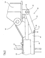
- FIG. 4 shows the central frame 12, which as a hollow support 40 with a cavity 41 is trained.
- the respective hydraulic cylinder 22 is in the cavity 41 of the carrier, 22 'housed.
- the articulation points 42, 43 for the hydraulic cylinder are in the hollow support 40 22 provided, while the articulation points 45, 46 for the piston rod of Hydraulic cylinders 22 are connected to the respective side frames 13, 14.
- Fig. 4 also illustrates the arrangement of a transport lock 50 with Latch bolt 51.
- the latch bolt 51 In the transport direction, the latch bolt 51 is supported against the edge 51 ' of the hollow beam 40.
- the latch bolt 51 is at a distance from the pivot axis 16 connected to the side frame 14 via the articulation point 46. This distance makes it easier the application of the necessary force for pivoting the side frame 13 or 14.
- Fig. 5 corresponds essentially to Fig. 4, only that here an auxiliary device is shown with which the latch bolt 51 from the locked position shown in FIG. 4 again can be moved out.
- 4 clearly shows that on the bottom of the Central frame 12 sliding end 55 of the latch bolt 51 has a nose 56 which gets caught behind the edge 51 'in the end position or the latch bolt is supported 51 allowed on this edge 51 '. 5 is used to unlock the latch bolt 51st a pawl 53 with cable 52.
- the pawl 53 is articulated on the central frame 12 and has at its lower edge an inwardly facing plate 53 ', which at Operating the cable 52 raises the latch 51 and unlocks it.
- the latchbolt 51 which is articulated at the end 54 around the articulation point 46, can accordingly pushed back into the interior of the hollow support 40 after swiveling up be what is done by retracting the piston rod of the hydraulic cylinder 22.
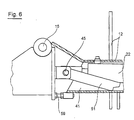
- Fig. 6 finally illustrates the protected housing of the hydraulic cylinder 22 and the latch bolt 51 in the unfolded working position.
- This unfolded Working position is limited by a stop 59 which is adjustable.
Landscapes
- Life Sciences & Earth Sciences (AREA)
- Engineering & Computer Science (AREA)
- Mechanical Engineering (AREA)
- Soil Sciences (AREA)
- Environmental Sciences (AREA)
- Agricultural Machines (AREA)
- Soil Working Implements (AREA)
Description
- Fig. 1
- eine Kreiselegge in Rückansicht mit einer eingeklappten und einer ausgeklappten Geräteeinheit,
- Fig. 2
- eine ausgeklappte Geräteeinheit in Vorderansicht,
- Fig. 3
- eine ausgeklappte Geräteeinheit in Draufsicht,
- Fig. 4
- eine Detailansicht der Verriegelung in verriegelter Transportstellung,
- Fig. 5
- eine Teilansicht der Verriegelung mit Auslösemechanismus und
- Fig. 6
- eine Detailansicht der Verriegelung in entriegelter Arbeitsstellung.
Claims (13)
- Bodenbearbeitungsgerät, insbesondere Kreiselegge (1), mit mindestens zwei über je ein Getriebe (70) angetriebenen Geräteeinheiten (2, 3), die in Arbeitsstellung quer zur Arbeitsrichtung des Zugfahrzeuges angeordnet und mit einem an das Zugfahrzeug ankoppelbaren Tragrahmen (9), um den die Geräteeinheiten (2, 3) über Hydraulikzylinder (22) in eine Transportstellung schwenkbar angeordnet sind, wobei der Tragrahmen (9) aus einem Zentralrahmen (12) und mit den Geräteeinheiten (2, 3) verbundenen Seitenrahmen (13, 14) besteht, dadurch gekennzeichnet, daß der Zentralrahmen (12) als bezüglich des Hohlraumes (41) den Hydraulikzylindern (22) angepasster Hohlträger (40) mit im Hohlträger angeordneten Anlenkpunkten (42, 43) für die Hydraulikzylinder (22) ausgebildet ist und wobei die Seitenrahmen (13, 14) jeweils korrespondierende Anschlagpunkte (45, 46) aufweisen und dass die mit dem Zentralrahmen (12) verbundenen Seitenrahmen (13, 14) über in Arbeitsrichtung und horizontal angeordnete jeweils beidseitig eines Getriebes (70) liegende Schwenklagerungen (17, 18) für die Geräteeinheiten (2, 3) verfügen, die annähernd mittig der Geräteeinheiten (2, 3) angeordnet sind und eine in deren Längsrichtung vor und eine hinter dem Getriebe (70) positionierte Lagerstelle (17', 18') aufweisen, wobei die Seitenrahmen (13, 14) das Getriebe (70) U-förmig umgreifend ausgebildet sind.
- Bodenbearbeitungsgerät nach Anspruch 1,
dadurch gekennzeichnet,
dass die Seitenrahmen (13, 14) um horizontale, in Arbeitsrichtung versetzt liegende Schwenkachsen (15, 16) schwenkbar ausgebildet sind und dass die Anlenkpunkte (45, 46) im Abstand dazu vor Kopf der Seitenrahmen (13, 14) liegend angeordnet sind. - Bodenbearbeitungsgerät nach einem der vorhergehenden Ansprüche,
dadurch gekennzeichnet,
dass der Zentralrahmen (12) endseitig offen und etwa mittig die Anlenkpunkte (42, 43) für je einen Hydraulikzylinder (22, 22') aufweisend ausgebildet ist. - Bodenbearbeitungsgerät nach einem der vorhergehenden Ansprüche,
dadurch gekennzeichnet,
dass der Zentralrahmen (12) als nach unten offenes, einige über die Länge verteilt angeordnete Querverbinder aufweisendes U-Profil ausgebildet ist. - Bodenbearbeitungsgerät nach einem der vorhergehenden Ansprüche,
dadurch gekennzeichnet,
dass die Schwenklagerungen (17, 18) Pendelachsen aufweisen, die in ihrer Schwenkfreiheit begrenzbar ausgebildet sind. - Bodenbearbeitungsgerät nach einem der vorhergehenden Ansprüche,
dadurch gekennzeichnet,
dass den Seitenrahmen (13, 14) eine gegen ein unbeabsichtigtes Ausschwenken der Geräteeinheiten (2, 3) sperrende Transportverriegelung (50) zugeordnet ist. - Bodenbearbeitungsgerät nach einem der vorhergehenden Ansprüche,
dadurch gekennzeichnet,
dass die Transportverriegelung (50) über einen im Hohlträger (40) verschieblich angeordneten Fallriegel (51) verfügt, der an einem Ende (54) über den Anlenkpunkt (45; 46) mit dem Seitenrahmen (13; 14) gelenkig verbunden ist und am anderen, auf dem Boden des Hohlträgers (40) schleifenden Ende (55) eine sich im Sperrzustand gegen die Kante (51') des Hohlträgers (40) abstützende Nase (56) aufweist. - Bodenbearbeitungsgerät nach einem der vorhergehenden Ansprüche,
dadurch gekennzeichnet,
dass dem Fallriegel (51) eine Klinke (53) mit Seilzug (52) zugeordnet ist, die am Zentralrahmen (12) schwenkbar angeordnet ist und eine gegen den Fallriegel (51) anhebbare Platte (53') aufweist. - Bodenbearbeitungsgerät nach einem der vorhergehenden Ansprüche,
dadurch gekennzeichnet,
dass die Seitenrahmen (13, 14) und der Zentralrahmen (12) einen die ausgeklappte Stellung vorgebenden, einstellbar ausgebildeten Anschlag (59) aufweisen. - Bodenbearbeitungsgerät nach einem der vorhergehenden Ansprüche,
dadurch gekennzeichnet,
dass die um den Hohlträger (50) schwenkbar gelagerten Geräteeinheiten (2, 3) mit einer die Erde über eine Führungsschiene (62) nach innen leitenden Seitenplatte (61) ausgerüstet sind. - Bodenbearbeitungsgerät nach einem der vorhergehenden Ansprüche,
dadurch gekennzeichnet,
dass die Seitenplatten (61) um der Oberseite (65) der Geräteeinheiten (2, 3) zugeordnete horizontale Achsen (63) schwenkbar angeordnet sind. - Bodenbearbeitungsgerät nach einem der vorhergehenden Ansprüche,
dadurch gekennzeichnet,
dass die Führungsschiene (62) höhenverstellbar mit der Seitenplatte (61) verbunden ist. - Bodenbearbeitungsgerät nach einem der vorhergehenden Ansprüche,
dadurch gekennzeichnet,
dass die Führungsschiene (62) in Fahrtrichtung bzw. entgegengesetzt verschiebbar mit der Seitenplatte (61) verbunden ist.
Applications Claiming Priority (4)
| Application Number | Priority Date | Filing Date | Title |
|---|---|---|---|
| DE19720965 | 1997-05-17 | ||
| DE19720965 | 1997-05-17 | ||
| DE19817608 | 1998-04-21 | ||
| DE19817608A DE19817608A1 (de) | 1997-05-17 | 1998-04-24 | Einklappbare Kreiselegge mit integrierten Schwenkzylindern |
Publications (2)
| Publication Number | Publication Date |
|---|---|
| EP0878118A1 EP0878118A1 (de) | 1998-11-18 |
| EP0878118B1 true EP0878118B1 (de) | 2001-08-29 |
Family
ID=26036660
Family Applications (1)
| Application Number | Title | Priority Date | Filing Date |
|---|---|---|---|
| EP98108649A Expired - Lifetime EP0878118B1 (de) | 1997-05-17 | 1998-05-13 | Einklappbare Kreiselegge mit integrierten Schwenkzylindern |
Country Status (4)
| Country | Link |
|---|---|
| EP (1) | EP0878118B1 (de) |
| AT (1) | ATE204699T1 (de) |
| DK (1) | DK0878118T3 (de) |
| PL (1) | PL186125B1 (de) |
Cited By (1)
| Publication number | Priority date | Publication date | Assignee | Title |
|---|---|---|---|---|
| DE102015118354A1 (de) | 2015-10-27 | 2017-04-27 | Lemken Gmbh & Co. Kg | Landwirtschaftlicher Maschinenrahmen |
Families Citing this family (2)
| Publication number | Priority date | Publication date | Assignee | Title |
|---|---|---|---|---|
| GB0118746D0 (en) * | 2001-08-01 | 2001-09-26 | Moate George | Agricultural implement |
| CN108770402B (zh) * | 2018-07-06 | 2021-09-03 | 甘肃省机械科学研究院有限责任公司 | 一种农作物收获机用可活动机架及其折叠方法和应用 |
Family Cites Families (7)
| Publication number | Priority date | Publication date | Assignee | Title |
|---|---|---|---|---|
| NL6406213A (de) * | 1964-06-03 | 1965-12-06 | ||
| GB1531403A (en) * | 1977-04-18 | 1978-11-08 | Int Harvester Co | Folding tool bar for agricultural implements |
| NL8001263A (nl) | 1980-03-03 | 1981-10-01 | Lely Nv C Van Der | Landbouwwerktuig, in het bijzonder grondbewerkingsmachine. |
| GB2198323B (en) * | 1986-11-26 | 1991-01-23 | Cousins Norman | Ground or crop treatment implements. |
| US4923017A (en) * | 1989-09-06 | 1990-05-08 | Kinze Manufacturing, Inc. | Hinge for vertically folding wing section of agricultural implement |
| EP0422721A1 (de) * | 1989-10-10 | 1991-04-17 | C. van der Lely N.V. | Landwirtschaftliches Gerät, insbesondere Bodenbearbeitungsmaschine |
| DE29516162U1 (de) | 1995-08-18 | 1995-12-07 | Lemken KG, 46519 Alpen | Bodenbearbeitungsgerät |
-
1998
- 1998-05-13 DK DK98108649T patent/DK0878118T3/da active
- 1998-05-13 AT AT98108649T patent/ATE204699T1/de not_active IP Right Cessation
- 1998-05-13 EP EP98108649A patent/EP0878118B1/de not_active Expired - Lifetime
- 1998-05-16 PL PL98326341A patent/PL186125B1/pl unknown
Cited By (2)
| Publication number | Priority date | Publication date | Assignee | Title |
|---|---|---|---|---|
| DE102015118354A1 (de) | 2015-10-27 | 2017-04-27 | Lemken Gmbh & Co. Kg | Landwirtschaftlicher Maschinenrahmen |
| WO2017071691A1 (de) | 2015-10-27 | 2017-05-04 | Lemken Gmbh & Co Kg | Landwirtschaftlicher maschinenrahmen |
Also Published As
| Publication number | Publication date |
|---|---|
| PL326341A1 (en) | 1998-11-23 |
| ATE204699T1 (de) | 2001-09-15 |
| EP0878118A1 (de) | 1998-11-18 |
| DK0878118T3 (da) | 2001-12-17 |
| PL186125B1 (pl) | 2003-10-31 |
Similar Documents
| Publication | Publication Date | Title |
|---|---|---|
| EP2175070B1 (de) | Straßenfräsmaschine | |
| DE2737053B2 (de) | Landwirtschaftlich nutzbares Arbeitsgerät | |
| EP0182229A2 (de) | Arbeitsfahrzeug, insbesondere Ackerschlepper mit einer Anschluss- und Kupplungsvorrichtung zum frontseitigen Anbau | |
| DE3024664A1 (de) | Landwirtschaftliches mehrzweckfahrzeug | |
| DE112013001318T5 (de) | Geräterahmen mit nach vorne faltbaren Flügeln | |
| DE1915825A1 (de) | Bodenbearbeitungsgeraet | |
| EP1008284A2 (de) | Teleskopierbarer Geräteanbau eines Kraftfahrzeugs | |
| EP1657400B1 (de) | Bauarbeitsgerät | |
| DE1582356A1 (de) | Maehmaschine | |
| EP1077306B1 (de) | Fahrbares Arbeitsgerät | |
| EP0878118B1 (de) | Einklappbare Kreiselegge mit integrierten Schwenkzylindern | |
| EP1068780A1 (de) | Verschwenkbarer Geräteanbau eines Kraftfahrzeugs | |
| DE3217397C2 (de) | Anordnung eines Mähwerks mit Tragbalken an einem Schlepper | |
| DE1222726B (de) | Kupplungsvorrichtung zwischen einem Schlepper und einem an diesen anzubauenden Arbeitsgeraet | |
| DE3238945A1 (de) | Vorrichtung zum setzen von schneestangen oder dgl. | |
| DE19817608A1 (de) | Einklappbare Kreiselegge mit integrierten Schwenkzylindern | |
| DE19806057A1 (de) | Baumaschinenadapter | |
| DE3831186A1 (de) | Heuwerbungsmaschine | |
| DE2440655A1 (de) | Bodenbearbeitungsgeraet fuer schlepperzug mit grosser arbeitsbreite | |
| EP2106933A1 (de) | Anordnung zur höhenverstellbaren Anbringung einer Anhängekupplung an einem Zugfahrzeug | |
| EP0594160A1 (de) | Maschine insbesondere zum Einsatz in Baumschulen, Gärten und dergleichen | |
| DE2835049A1 (de) | Selbstfahrende, insbesondere landwirtschaftliche arbeitsmaschine mit wechselaufbau | |
| EP4311909B1 (de) | Arbeitsgerät mit mäkler | |
| EP1008283A1 (de) | Verfahren und Vorrichtung zum Ankuppeln eies Geräts | |
| DE202016102833U1 (de) | Baggerarm mit Werkzeughalterung |
Legal Events
| Date | Code | Title | Description |
|---|---|---|---|
| PUAI | Public reference made under article 153(3) epc to a published international application that has entered the european phase |
Free format text: ORIGINAL CODE: 0009012 |
|
| AK | Designated contracting states |
Kind code of ref document: A1 Designated state(s): AT BE CH DE DK FR GB IT LI NL |
|
| AX | Request for extension of the european patent |
Free format text: AL;LT;LV;MK;RO;SI |
|
| 17P | Request for examination filed |
Effective date: 19990302 |
|
| AKX | Designation fees paid |
Free format text: AT BE CH DE DK FR GB IT LI NL |
|
| 17Q | First examination report despatched |
Effective date: 19990628 |
|
| GRAG | Despatch of communication of intention to grant |
Free format text: ORIGINAL CODE: EPIDOS AGRA |
|
| GRAG | Despatch of communication of intention to grant |
Free format text: ORIGINAL CODE: EPIDOS AGRA |
|
| GRAH | Despatch of communication of intention to grant a patent |
Free format text: ORIGINAL CODE: EPIDOS IGRA |
|
| GRAH | Despatch of communication of intention to grant a patent |
Free format text: ORIGINAL CODE: EPIDOS IGRA |
|
| GRAA | (expected) grant |
Free format text: ORIGINAL CODE: 0009210 |
|
| AK | Designated contracting states |
Kind code of ref document: B1 Designated state(s): AT BE CH DE DK FR GB IT LI NL |
|
| REF | Corresponds to: |
Ref document number: 204699 Country of ref document: AT Date of ref document: 20010915 Kind code of ref document: T |
|
| REG | Reference to a national code |
Ref country code: CH Ref legal event code: EP |
|
| REF | Corresponds to: |
Ref document number: 59801281 Country of ref document: DE Date of ref document: 20011004 |
|
| GBT | Gb: translation of ep patent filed (gb section 77(6)(a)/1977) |
Effective date: 20011117 |
|
| REG | Reference to a national code |
Ref country code: GB Ref legal event code: IF02 |
|
| EN | Fr: translation not filed | ||
| PG25 | Lapsed in a contracting state [announced via postgrant information from national office to epo] |
Ref country code: LI Free format text: LAPSE BECAUSE OF NON-PAYMENT OF DUE FEES Effective date: 20020531 Ref country code: CH Free format text: LAPSE BECAUSE OF NON-PAYMENT OF DUE FEES Effective date: 20020531 |
|
| PLBE | No opposition filed within time limit |
Free format text: ORIGINAL CODE: 0009261 |
|
| 26N | No opposition filed | ||
| REG | Reference to a national code |
Ref country code: CH Ref legal event code: PL |
|
| ET | Fr: translation filed | ||
| REG | Reference to a national code |
Ref country code: FR Ref legal event code: ERR Free format text: BOPI DE PUBLICATION N: 02/04 PAGES: 244 PARTIE DU BULLETIN CONCERNEE: BREVETS EUROPEENS DONT LA TRADUCTION N'A PAS ETE REMISE A I'INPI IL Y A LIEU DE SUPPRIMER: LA MENTION DE LA NON REMISE. LA REMISE DE LA TRADUCTION EST PUBLIEE DANS LE PRESENT BOPI. |
|
| PGFP | Annual fee paid to national office [announced via postgrant information from national office to epo] |
Ref country code: AT Payment date: 20080514 Year of fee payment: 11 |
|
| PGFP | Annual fee paid to national office [announced via postgrant information from national office to epo] |
Ref country code: NL Payment date: 20080501 Year of fee payment: 11 |
|
| PGFP | Annual fee paid to national office [announced via postgrant information from national office to epo] |
Ref country code: BE Payment date: 20081128 Year of fee payment: 11 |
|
| BERE | Be: lapsed |
Owner name: *LEMKEN G.M.B.H. & CO. K.G. Effective date: 20090531 |
|
| PG25 | Lapsed in a contracting state [announced via postgrant information from national office to epo] |
Ref country code: AT Free format text: LAPSE BECAUSE OF NON-PAYMENT OF DUE FEES Effective date: 20090513 |
|
| NLV4 | Nl: lapsed or anulled due to non-payment of the annual fee |
Effective date: 20091201 |
|
| PG25 | Lapsed in a contracting state [announced via postgrant information from national office to epo] |
Ref country code: NL Free format text: LAPSE BECAUSE OF NON-PAYMENT OF DUE FEES Effective date: 20091201 |
|
| PG25 | Lapsed in a contracting state [announced via postgrant information from national office to epo] |
Ref country code: BE Free format text: LAPSE BECAUSE OF NON-PAYMENT OF DUE FEES Effective date: 20090531 |
|
| REG | Reference to a national code |
Ref country code: FR Ref legal event code: PLFP Year of fee payment: 19 |
|
| REG | Reference to a national code |
Ref country code: FR Ref legal event code: PLFP Year of fee payment: 20 |
|
| PGFP | Annual fee paid to national office [announced via postgrant information from national office to epo] |
Ref country code: DK Payment date: 20170526 Year of fee payment: 20 Ref country code: FR Payment date: 20170530 Year of fee payment: 20 Ref country code: DE Payment date: 20170512 Year of fee payment: 20 Ref country code: GB Payment date: 20170530 Year of fee payment: 20 |
|
| PGFP | Annual fee paid to national office [announced via postgrant information from national office to epo] |
Ref country code: IT Payment date: 20170525 Year of fee payment: 20 |
|
| REG | Reference to a national code |
Ref country code: DE Ref legal event code: R071 Ref document number: 59801281 Country of ref document: DE |
|
| REG | Reference to a national code |
Ref country code: DK Ref legal event code: EUP Effective date: 20180513 |
|
| REG | Reference to a national code |
Ref country code: GB Ref legal event code: PE20 Expiry date: 20180512 |
|
| PG25 | Lapsed in a contracting state [announced via postgrant information from national office to epo] |
Ref country code: GB Free format text: LAPSE BECAUSE OF EXPIRATION OF PROTECTION Effective date: 20180512 |