EP0877331A2 - Système de communication sans fil - Google Patents
Système de communication sans fil Download PDFInfo
- Publication number
- EP0877331A2 EP0877331A2 EP98107483A EP98107483A EP0877331A2 EP 0877331 A2 EP0877331 A2 EP 0877331A2 EP 98107483 A EP98107483 A EP 98107483A EP 98107483 A EP98107483 A EP 98107483A EP 0877331 A2 EP0877331 A2 EP 0877331A2
- Authority
- EP
- European Patent Office
- Prior art keywords
- receiving device
- data
- energy
- transmitter
- memory
- Prior art date
- Legal status (The legal status is an assumption and is not a legal conclusion. Google has not performed a legal analysis and makes no representation as to the accuracy of the status listed.)
- Granted
Links
Images
Classifications
-
- G—PHYSICS
- G06—COMPUTING; CALCULATING OR COUNTING
- G06K—GRAPHICAL DATA READING; PRESENTATION OF DATA; RECORD CARRIERS; HANDLING RECORD CARRIERS
- G06K19/00—Record carriers for use with machines and with at least a part designed to carry digital markings
- G06K19/06—Record carriers for use with machines and with at least a part designed to carry digital markings characterised by the kind of the digital marking, e.g. shape, nature, code
- G06K19/067—Record carriers with conductive marks, printed circuits or semiconductor circuit elements, e.g. credit or identity cards also with resonating or responding marks without active components
- G06K19/07—Record carriers with conductive marks, printed circuits or semiconductor circuit elements, e.g. credit or identity cards also with resonating or responding marks without active components with integrated circuit chips
- G06K19/0701—Record carriers with conductive marks, printed circuits or semiconductor circuit elements, e.g. credit or identity cards also with resonating or responding marks without active components with integrated circuit chips at least one of the integrated circuit chips comprising an arrangement for power management
-
- G—PHYSICS
- G06—COMPUTING; CALCULATING OR COUNTING
- G06K—GRAPHICAL DATA READING; PRESENTATION OF DATA; RECORD CARRIERS; HANDLING RECORD CARRIERS
- G06K19/00—Record carriers for use with machines and with at least a part designed to carry digital markings
- G06K19/06—Record carriers for use with machines and with at least a part designed to carry digital markings characterised by the kind of the digital marking, e.g. shape, nature, code
- G06K19/067—Record carriers with conductive marks, printed circuits or semiconductor circuit elements, e.g. credit or identity cards also with resonating or responding marks without active components
- G06K19/07—Record carriers with conductive marks, printed circuits or semiconductor circuit elements, e.g. credit or identity cards also with resonating or responding marks without active components with integrated circuit chips
- G06K19/0723—Record carriers with conductive marks, printed circuits or semiconductor circuit elements, e.g. credit or identity cards also with resonating or responding marks without active components with integrated circuit chips the record carrier comprising an arrangement for non-contact communication, e.g. wireless communication circuits on transponder cards, non-contact smart cards or RFIDs
-
- G—PHYSICS
- G06—COMPUTING; CALCULATING OR COUNTING
- G06K—GRAPHICAL DATA READING; PRESENTATION OF DATA; RECORD CARRIERS; HANDLING RECORD CARRIERS
- G06K7/00—Methods or arrangements for sensing record carriers, e.g. for reading patterns
- G06K7/0008—General problems related to the reading of electronic memory record carriers, independent of its reading method, e.g. power transfer
-
- G—PHYSICS
- G07—CHECKING-DEVICES
- G07C—TIME OR ATTENDANCE REGISTERS; REGISTERING OR INDICATING THE WORKING OF MACHINES; GENERATING RANDOM NUMBERS; VOTING OR LOTTERY APPARATUS; ARRANGEMENTS, SYSTEMS OR APPARATUS FOR CHECKING NOT PROVIDED FOR ELSEWHERE
- G07C9/00—Individual registration on entry or exit
- G07C9/00174—Electronically operated locks; Circuits therefor; Nonmechanical keys therefor, e.g. passive or active electrical keys or other data carriers without mechanical keys
- G07C2009/00634—Power supply for the lock
Definitions
- the invention relates to a wireless data transmission system according to the preamble of claim 1.
- a data transmission system is known from DE PS 40 03 410 C2 known.
- This known system comprises a read / write unit with a data transmitter, a data receiver, a memory and an input unit and a detection plate with a data transmitter, a data receiver and a memory.
- the data transmitter of the read / write unit is simultaneous trained as an energy transmitter and transmits it to operation of the detection plate required energy to an energy receiver on the detection plate.
- the detection plate and the read / write unit can both mobile or one of the two components can be mobile and that others are operated stationary.
- the read / write unit can be arranged stationary and be connected to a door opener.
- the energy supply the read / write unit and the door opener are off the low-voltage network.
- the detection plates are from authorized persons. As soon as a detection plate near an antenna of the read / write unit is brought, their data from the read / write unit read and checked for validity. If valid, the Door release released. By writing to the memory of the Detection plates can contain data and therefore access authorizations be changed.
- the invention has for its object in a wireless Data transmission system the functional security and manipulation security to improve.
- the receiving device can tamper-proof installed or housed, because the energy supply of all components, including of the sensor and / or actuator takes place wirelessly and so that it can always be ensured from the outside.
- the functional reliability is so high that emergency measures for Bridging disturbances, which are equilateral but also those Manipulation security would be compromised can.
- the energy recipient can include temporary energy storage by energy transfer from the transmitter arrangement to the receiving device is rechargeable and briefly the energy supply of the sensor and / or actuator takes over.
- the energy transfer does not have to be simultaneous with the operation of the sensor and / or actuator. Furthermore there is a possibility at a low average Briefly increase the energy flow to the energy receiver To cover energy needs.
- the energy supply to the sensor and / or Actuator only through wireless energy transfer during its operation take place.
- the power supply to the sensor and / or actuator both by wireless energy transmission during its operation as well as by buffering by a temporary energy storage is done by wireless Energy transfer is rechargeable.
- the energy store can be smaller than in the first-mentioned variant, because it is only for Bridging energy peaks is needed.
- the energy transmitter can work together with the data transmitter and data receiver the encoder arrangement combined or as a separate Device be trained.
- the energy transmitter with the data transmitter and Data receiver of the encoder arrangement increases its weight and size, while in the other case in Normally the handling of the encoder arrangement is easier, if the power supply fails, an additional device is needed.
- the receiving device can comprise a decoder, which at the request of the control unit of the receiving device from evaluates the authentication data sent to the transmitter arrangement and if the authentication data is valid, the memory and / or sensor and / or actuator releases.
- This measure increases security against manipulation, by taking encoder units that the transmission protocol for master the data transmission to the receiving device and back, permissions can be assigned selectively, which are queried by the receiving device.
- the permissions can also be changed by changing the memory contents to change.
- the encoder arrangement can be stored in the memory as well as in the memory of the receiving device Authentication data must be stored. Furthermore, both in the encoder arrangement as well as in the receiving device decoder be provided by means of which the other on request transmitted authentication data for validity are verifiable. There can be a bidirectional data exchange take place between the encoder arrangement and the receiving device and only if both authentication data of the Memory of the receiving device and / or the sensor and / or the actuator are released.
- test algorithm can contain exclusive identification numbers of the Partner authorized to communicate from donor orders and include receiving units.
- the transmitter arrangement and / or are preferably stored in the memory the receiving device protocol data of the data communication and authentication data stored. So it can Transmitter arrangement log which receiving devices have been operated and the receiving device can log which donors carried out the authentication process to have.
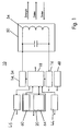
- the encoder arrangement shown as a block diagram in FIG. 1 10 includes a data transmitter 14, which also simultaneously as Energy transmitter 34 is used, a data receiver 16, a memory 20, a keyboard 44, a display 46, a control unit 18, an energy source 48 and one at the same time Transmitting and receiving antenna resonant circuit 50.
- About the oscillating circuit 50 becomes data and energy for the receiving device 12 transmitted and from the receiving device 12 received data.
- Control of the data transmitter 14 and data receiver 16 and the memory 20, the display and the keyboard is done by the control unit 18.
- Die Control unit 18 also takes on the function of a Decoder 40 for checking the validity of received Data.
- the memory 20 is divided into a rewritable one Area and a non-writable or one-time writable Area in which an exclusive identification number of the Encoder arrangement 10 is stored.
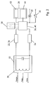
- the receiving device shown in Fig. 2 as a block diagram 12 partially has similar functional blocks as that
- the encoder arrangement 10 described above is also the case with the receiving device 12 a data transmitter 24, a data receiver 22, a memory 28, a control unit 26 and a simultaneously resonant circuit 52 serving as transmitting and receiving antenna available.
- the data receiver 22 simultaneously forms one Energy receiver 36.
- Via the resonant circuit 52 data transferred to the encoder arrangement 10 and from the encoder arrangement 10 data and energy received.
- the control of the Data transmitter 24 and data receiver 22 and the memory 28 is carried out by the control unit 26
- Control unit 26 the function of a decoder 42 for testing the validity of received data.
- the memory 28 is divided into a repeatable area and an area that cannot be written or written once, in which a exclusive identification number of the receiving device 12 is stored is.
- a temporary energy store 38 to be available.
- the receiving device 12 has an actuator 32 and a sensor 30 connected.
- the actuator 32 and the sensor 30 are controlled by the control unit 26.
- the energy supply of the actuator 32 and sensor 30 takes place wirelessly from the Encoder arrangement 10 for the receiving device 12.
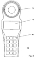
- FIG. 3 shows an embodiment of a transmitter arrangement 10
- Function blocks described in Fig. 1 are here in one shared housing. It is externally visible Display 46 and keyboard 44. Furthermore, an area can be seen, in which the coil 54 of the resonant circuit 50 is accommodated is. In this case, the coil 54 is dimensioned such that also the energy for operating the sensor 30 and the actuator 32 Receiving device 12 can be transmitted.
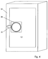
- the receiving device 12 comprises the functional blocks from Fig. 2 and further an actuator 32 and a sensor 30.
- Der Sensor 30 can be designed as a temperature sensor, for example be the temperature inside a container 56 or Detect container and monitor from the outside.
- Actuator 32 is designed here as a motor bolt to mechanically lock the door to lock and unlock without a mechanical Key is needed.
- the coil 58 of the resonant circuit 52 can be seen, which is approximately the same size as the coil 54 in the transmitter arrangement 10 is matched. This is an optimal one Coupling and thus maximum energy transfer guaranteed.
- the application described here for installing the receiving device 12 in a container 56 is particularly predestined for the invention, since the receiving device 12, with exceptions, not from the public low-voltage network can be supplied with energy and with battery operation there is no guarantee that necessary maintenance work will be carried out be carried out on time.
- both the energy for operating the functional blocks of the receiving device 12 as well as for operating the sensor 30 and the actuator 32 wirelessly transfer.
- the lock can therefore only from one encoder arrangement 10, which is authorized to do so.
- a mechanical one Opening without using the transmitter assembly 10 is not possible or only by destroying container 56. This results in a high degree of security against manipulation.
- the transmitter arrangement 10 and the receiving device 12 each other's authentication data through a test algorithm changed and retransmitted. Because the test algorithm both devices are known, the validity of the Authentication data can be checked without it being intercepted succeeds in decrypting the authentication data. The authentication data is updated with every new transmission changed.
- the test algorithm can be influenced by the identification numbers will. Only when the devices connected to each other have determined the validity of the identification data, the memory 28 as well as the actuator 32 and the sensor 30 released by the control unit 26 of the receiving device 12.
Applications Claiming Priority (2)
| Application Number | Priority Date | Filing Date | Title |
|---|---|---|---|
| DE19719562A DE19719562A1 (de) | 1997-05-09 | 1997-05-09 | Drahtloses Datenübertragungssystem |
| DE19719562 | 1997-05-09 |
Publications (3)
| Publication Number | Publication Date |
|---|---|
| EP0877331A2 true EP0877331A2 (fr) | 1998-11-11 |
| EP0877331A3 EP0877331A3 (fr) | 1999-10-20 |
| EP0877331B1 EP0877331B1 (fr) | 2003-08-20 |
Family
ID=29265469
Family Applications (2)
| Application Number | Title | Priority Date | Filing Date |
|---|---|---|---|
| EP98107287A Expired - Lifetime EP0877333B1 (fr) | 1997-05-09 | 1998-04-22 | Appareil pour le transfert d'énergie sans fil et exécution d'une action |
| EP98107483A Expired - Lifetime EP0877331B1 (fr) | 1997-05-09 | 1998-04-24 | Système de communication sans fil |
Family Applications Before (1)
| Application Number | Title | Priority Date | Filing Date |
|---|---|---|---|
| EP98107287A Expired - Lifetime EP0877333B1 (fr) | 1997-05-09 | 1998-04-22 | Appareil pour le transfert d'énergie sans fil et exécution d'une action |
Country Status (2)
| Country | Link |
|---|---|
| EP (2) | EP0877333B1 (fr) |
| DE (3) | DE19719562A1 (fr) |
Cited By (6)
| Publication number | Priority date | Publication date | Assignee | Title |
|---|---|---|---|---|
| WO2001082447A1 (fr) * | 2000-04-20 | 2001-11-01 | Abb Research Ltd. | Capteur avec alimentation en energie sans fil |
| WO2005078667A1 (fr) * | 2004-02-13 | 2005-08-25 | Melexis Nv | Dispositif de verrouillage |
| WO2007079332A2 (fr) * | 2005-12-14 | 2007-07-12 | Checkpoint Systems, Inc. | Systemes et procedes pour la securite universelle d'articles |
| WO2008043192A2 (fr) * | 2006-10-09 | 2008-04-17 | Legic Identsystems Ag | Dispositif et procédé pour faire fonctionner un appareil d'écriture/de lecture |
| EP2051189A1 (fr) * | 2007-10-18 | 2009-04-22 | Siemens Aktiengesellschaft | Dispositif pour l'identification électronique d'articles |
| EP2425516B1 (fr) | 2009-04-30 | 2015-12-23 | Assa Abloy Ab | Système d'alimentation externe d'une serrure comportant des moyens de communication sans contact de type nfc |
Families Citing this family (8)
| Publication number | Priority date | Publication date | Assignee | Title |
|---|---|---|---|---|
| DE59913632D1 (de) * | 1999-01-08 | 2006-08-10 | Anatoli Stobbe | Sicherungssystem, Transponder und Empfangsvorrichtung |
| DE10233597A1 (de) * | 2002-07-24 | 2004-02-05 | Brühn, Xenia | Optoakustische Signalgebung vom elektronischen Ausweis oder Transponder als Methode zur Warnung vor illegalen Zugriffsversuchen auf schlüssellos arbeitende Zugangssysteme |
| DE10348569A1 (de) * | 2003-10-20 | 2005-05-25 | Giesecke & Devrient Gmbh | Vorrichtung zum Ansteuern eines Aktuators |
| DE102005036290B4 (de) * | 2005-08-02 | 2009-04-30 | Gebrüder Frei GmbH & Co. KG | Bedienungssystem |
| DE102009043571B3 (de) * | 2009-09-30 | 2011-02-17 | Festo Ag & Co. Kg | Fluidisch-elektrische Einrichtung mit drahtloser Energiespeisung |
| DE102012102007A1 (de) * | 2012-03-09 | 2013-09-12 | Infineon Technologies Ag | Leistungsversorgungsvorrichtung zum Liefern einer Spannung aus einem elektromagnetischen Feld |
| DE102014219088A1 (de) * | 2014-09-22 | 2016-03-24 | Siemens Aktiengesellschaft | Anordnung sowie ein Verfahren zum Schalten einer Schaltstrecke mittels eines Schaltgerätes |
| DE102014219089A1 (de) * | 2014-09-22 | 2016-03-24 | Siemens Aktiengesellschaft | Anordnung und Verfahren zum Schalten von Schaltstrecken mittels Schaltgeräten |
Citations (3)
| Publication number | Priority date | Publication date | Assignee | Title |
|---|---|---|---|---|
| EP0441237A1 (fr) * | 1990-02-05 | 1991-08-14 | Anatoli Stobbe | Plaquette détectrice portative programmable par champs |
| EP0634729A2 (fr) * | 1993-07-14 | 1995-01-18 | Philips Patentverwaltung GmbH | Dispositif d'échange de données |
| JPH10307898A (ja) * | 1997-05-09 | 1998-11-17 | Toppan Printing Co Ltd | 充電式非接触icカードシステム |
Family Cites Families (3)
| Publication number | Priority date | Publication date | Assignee | Title |
|---|---|---|---|---|
| JPS60119873A (ja) * | 1983-11-29 | 1985-06-27 | 日産自動車株式会社 | 車両用施錠制御装置 |
| US4829296A (en) * | 1986-04-30 | 1989-05-09 | Carey S. Clark | Electronic lock system |
| US5300875A (en) * | 1992-06-08 | 1994-04-05 | Micron Technology, Inc. | Passive (non-contact) recharging of secondary battery cell(s) powering RFID transponder tags |
-
1997
- 1997-05-09 DE DE19719562A patent/DE19719562A1/de not_active Withdrawn
-
1998
- 1998-04-22 DE DE59812235T patent/DE59812235D1/de not_active Expired - Lifetime
- 1998-04-22 EP EP98107287A patent/EP0877333B1/fr not_active Expired - Lifetime
- 1998-04-24 EP EP98107483A patent/EP0877331B1/fr not_active Expired - Lifetime
- 1998-04-24 DE DE59809318T patent/DE59809318D1/de not_active Expired - Lifetime
Patent Citations (3)
| Publication number | Priority date | Publication date | Assignee | Title |
|---|---|---|---|---|
| EP0441237A1 (fr) * | 1990-02-05 | 1991-08-14 | Anatoli Stobbe | Plaquette détectrice portative programmable par champs |
| EP0634729A2 (fr) * | 1993-07-14 | 1995-01-18 | Philips Patentverwaltung GmbH | Dispositif d'échange de données |
| JPH10307898A (ja) * | 1997-05-09 | 1998-11-17 | Toppan Printing Co Ltd | 充電式非接触icカードシステム |
Non-Patent Citations (1)
| Title |
|---|
| PATENT ABSTRACTS OF JAPAN vol. 099, no. 002, 26. Februar 1999 (1999-02-26) & JP 10 307898 A (TOPPAN PRINTING CO LTD), 17. November 1998 (1998-11-17) * |
Cited By (13)
| Publication number | Priority date | Publication date | Assignee | Title |
|---|---|---|---|---|
| WO2001082447A1 (fr) * | 2000-04-20 | 2001-11-01 | Abb Research Ltd. | Capteur avec alimentation en energie sans fil |
| WO2005078667A1 (fr) * | 2004-02-13 | 2005-08-25 | Melexis Nv | Dispositif de verrouillage |
| WO2007079332A2 (fr) * | 2005-12-14 | 2007-07-12 | Checkpoint Systems, Inc. | Systemes et procedes pour la securite universelle d'articles |
| WO2007079332A3 (fr) * | 2005-12-14 | 2007-09-20 | Checkpoint Systems Inc | Systemes et procedes pour la securite universelle d'articles |
| US8544742B2 (en) | 2006-10-09 | 2013-10-01 | Legic Idenstsystems Ag | Device and method for operating a read/write device |
| WO2008043192A3 (fr) * | 2006-10-09 | 2008-06-05 | Legic Identsystems Ag | Dispositif et procédé pour faire fonctionner un appareil d'écriture/de lecture |
| JP2010506274A (ja) * | 2006-10-09 | 2010-02-25 | レジック・アイデントシステムズ・アクチェンゲゼルシャフト | リード/ライトデバイスを動作させるデバイス及び方法 |
| WO2008043192A2 (fr) * | 2006-10-09 | 2008-04-17 | Legic Identsystems Ag | Dispositif et procédé pour faire fonctionner un appareil d'écriture/de lecture |
| CN101523407B (zh) * | 2006-10-09 | 2014-11-26 | 励智识别技术有限公司 | 用于操作读出/写入器的设备和方法 |
| EP2051189A1 (fr) * | 2007-10-18 | 2009-04-22 | Siemens Aktiengesellschaft | Dispositif pour l'identification électronique d'articles |
| US7970484B2 (en) | 2007-10-18 | 2011-06-28 | Siemens Aktiengesellschaft | Method of controlling a production process |
| EP2425516B1 (fr) | 2009-04-30 | 2015-12-23 | Assa Abloy Ab | Système d'alimentation externe d'une serrure comportant des moyens de communication sans contact de type nfc |
| EP2425516B2 (fr) † | 2009-04-30 | 2019-09-18 | Assa Abloy Ab | Système d'alimentation externe d'une serrure comportant des moyens de communication sans contact de type nfc |
Also Published As
| Publication number | Publication date |
|---|---|
| EP0877331A3 (fr) | 1999-10-20 |
| EP0877333A3 (fr) | 2002-01-16 |
| EP0877331B1 (fr) | 2003-08-20 |
| DE19719562A1 (de) | 1998-11-19 |
| DE59809318D1 (de) | 2003-09-25 |
| EP0877333B1 (fr) | 2004-11-10 |
| DE59812235D1 (de) | 2004-12-16 |
| EP0877333A2 (fr) | 1998-11-11 |
Similar Documents
| Publication | Publication Date | Title |
|---|---|---|
| EP0877331B1 (fr) | Système de communication sans fil | |
| DE3905651C2 (fr) | ||
| EP0788946B1 (fr) | Procédé et dispositif pour la programmation de données opérationnelles dans des pièces de voitures | |
| AT506344B1 (de) | Verfahren und vorrichtung zur steuerung der zutrittskontrolle | |
| DE19532617C2 (de) | Verfahren und Vorrichtung zur Versiegelung von Computerdaten | |
| WO1998029626A1 (fr) | Procede et dispositif pour controler l'etat de fermeture de verrous | |
| DE19502373C2 (de) | Verfahren zur Diebstahlsicherung motorangetriebener Kraftfahrzeuge | |
| WO2008116647A1 (fr) | Transpondeur doté d'une protection d'accès et procédé d'accès à un transpondeur | |
| DE3918052C1 (fr) | ||
| DE102004016548A1 (de) | Verfahren und Anordnung zur Überwachung der Ladung einer Transporteinrichtung | |
| EP1205885A2 (fr) | Système de serrure codable électroniquement | |
| EP2689401A1 (fr) | Procédé de commande d'une cassette de billets au moyen de clés spécifiques de clients | |
| DE4433499C2 (de) | Elektronisches Diebstahlschutzsystem für ein Kraftfahrzeug | |
| EP3567557A1 (fr) | Système de fermeture | |
| EP1784756B1 (fr) | Procédé et système de securité pour le codage sur et univoque d'un module de securité | |
| DE19743101B4 (de) | Verfahren zum Zuordnen eines Betätigungselementes zu einem Gerät | |
| EP0891607B1 (fr) | Procede d'exploitation d'un dispositif de telecommande et telecommande | |
| EP0825316B1 (fr) | Procédé et système pour inscrire une information de clé | |
| DE10152349B4 (de) | Sicherheitseinrichtung | |
| EP0596401B1 (fr) | Procédé d'individualisation et de synchronisation d'un appareil de commande | |
| EP1277632A2 (fr) | Procédé de commande à distance pour le verrouillage et/ou le déverrouillage d'un véhicule | |
| EP0879160B2 (fr) | Dispositif antivol pour automobiles et procede antivol | |
| EP0543176B1 (fr) | Installation de signalisation d'intrusion | |
| EP1389257B1 (fr) | Systeme de securite pour coffrets | |
| DE10044658A1 (de) | Einrichtung zur Überwachung und Registrierung von System- und Umgebungszuständen |
Legal Events
| Date | Code | Title | Description |
|---|---|---|---|
| PUAI | Public reference made under article 153(3) epc to a published international application that has entered the european phase |
Free format text: ORIGINAL CODE: 0009012 |
|
| AK | Designated contracting states |
Kind code of ref document: A2 Designated state(s): DE FR GB |
|
| AX | Request for extension of the european patent |
Free format text: AL;LT;LV;MK;RO;SI |
|
| PUAL | Search report despatched |
Free format text: ORIGINAL CODE: 0009013 |
|
| AK | Designated contracting states |
Kind code of ref document: A3 Designated state(s): AT BE CH CY DE DK ES FI FR GB GR IE IT LI LU MC NL PT SE |
|
| AX | Request for extension of the european patent |
Free format text: AL;LT;LV;MK;RO;SI |
|
| 17P | Request for examination filed |
Effective date: 19991231 |
|
| AKX | Designation fees paid |
Free format text: DE FR GB |
|
| GRAH | Despatch of communication of intention to grant a patent |
Free format text: ORIGINAL CODE: EPIDOS IGRA |
|
| GRAH | Despatch of communication of intention to grant a patent |
Free format text: ORIGINAL CODE: EPIDOS IGRA |
|
| GRAA | (expected) grant |
Free format text: ORIGINAL CODE: 0009210 |
|
| AK | Designated contracting states |
Designated state(s): DE FR GB |
|
| REG | Reference to a national code |
Ref country code: GB Ref legal event code: FG4D Free format text: NOT ENGLISH |
|
| REF | Corresponds to: |
Ref document number: 59809318 Country of ref document: DE Date of ref document: 20030925 Kind code of ref document: P |
|
| GBT | Gb: translation of ep patent filed (gb section 77(6)(a)/1977) |
Effective date: 20031209 |
|
| ET | Fr: translation filed | ||
| PLBE | No opposition filed within time limit |
Free format text: ORIGINAL CODE: 0009261 |
|
| STAA | Information on the status of an ep patent application or granted ep patent |
Free format text: STATUS: NO OPPOSITION FILED WITHIN TIME LIMIT |
|
| 26N | No opposition filed |
Effective date: 20040524 |
|
| PGFP | Annual fee paid to national office [announced via postgrant information from national office to epo] |
Ref country code: DE Payment date: 20120413 Year of fee payment: 15 |
|
| PGFP | Annual fee paid to national office [announced via postgrant information from national office to epo] |
Ref country code: GB Payment date: 20120423 Year of fee payment: 15 Ref country code: FR Payment date: 20120511 Year of fee payment: 15 |
|
| GBPC | Gb: european patent ceased through non-payment of renewal fee |
Effective date: 20130424 |
|
| PG25 | Lapsed in a contracting state [announced via postgrant information from national office to epo] |
Ref country code: DE Free format text: LAPSE BECAUSE OF NON-PAYMENT OF DUE FEES Effective date: 20131101 Ref country code: GB Free format text: LAPSE BECAUSE OF NON-PAYMENT OF DUE FEES Effective date: 20130424 |
|
| REG | Reference to a national code |
Ref country code: FR Ref legal event code: ST Effective date: 20131231 |
|
| PG25 | Lapsed in a contracting state [announced via postgrant information from national office to epo] |
Ref country code: FR Free format text: LAPSE BECAUSE OF NON-PAYMENT OF DUE FEES Effective date: 20130430 |
|
| REG | Reference to a national code |
Ref country code: DE Ref legal event code: R119 Ref document number: 59809318 Country of ref document: DE Effective date: 20131101 |