EP0877331A2 - Wireless communicationsystem - Google Patents
Wireless communicationsystem Download PDFInfo
- Publication number
- EP0877331A2 EP0877331A2 EP98107483A EP98107483A EP0877331A2 EP 0877331 A2 EP0877331 A2 EP 0877331A2 EP 98107483 A EP98107483 A EP 98107483A EP 98107483 A EP98107483 A EP 98107483A EP 0877331 A2 EP0877331 A2 EP 0877331A2
- Authority
- EP
- European Patent Office
- Prior art keywords
- receiving device
- data
- energy
- transmitter
- memory
- Prior art date
- Legal status (The legal status is an assumption and is not a legal conclusion. Google has not performed a legal analysis and makes no representation as to the accuracy of the status listed.)
- Granted
Links
Images
Classifications
-
- G—PHYSICS
- G06—COMPUTING; CALCULATING OR COUNTING
- G06K—GRAPHICAL DATA READING; PRESENTATION OF DATA; RECORD CARRIERS; HANDLING RECORD CARRIERS
- G06K19/00—Record carriers for use with machines and with at least a part designed to carry digital markings
- G06K19/06—Record carriers for use with machines and with at least a part designed to carry digital markings characterised by the kind of the digital marking, e.g. shape, nature, code
- G06K19/067—Record carriers with conductive marks, printed circuits or semiconductor circuit elements, e.g. credit or identity cards also with resonating or responding marks without active components
- G06K19/07—Record carriers with conductive marks, printed circuits or semiconductor circuit elements, e.g. credit or identity cards also with resonating or responding marks without active components with integrated circuit chips
- G06K19/0701—Record carriers with conductive marks, printed circuits or semiconductor circuit elements, e.g. credit or identity cards also with resonating or responding marks without active components with integrated circuit chips at least one of the integrated circuit chips comprising an arrangement for power management
-
- G—PHYSICS
- G06—COMPUTING; CALCULATING OR COUNTING
- G06K—GRAPHICAL DATA READING; PRESENTATION OF DATA; RECORD CARRIERS; HANDLING RECORD CARRIERS
- G06K19/00—Record carriers for use with machines and with at least a part designed to carry digital markings
- G06K19/06—Record carriers for use with machines and with at least a part designed to carry digital markings characterised by the kind of the digital marking, e.g. shape, nature, code
- G06K19/067—Record carriers with conductive marks, printed circuits or semiconductor circuit elements, e.g. credit or identity cards also with resonating or responding marks without active components
- G06K19/07—Record carriers with conductive marks, printed circuits or semiconductor circuit elements, e.g. credit or identity cards also with resonating or responding marks without active components with integrated circuit chips
- G06K19/0723—Record carriers with conductive marks, printed circuits or semiconductor circuit elements, e.g. credit or identity cards also with resonating or responding marks without active components with integrated circuit chips the record carrier comprising an arrangement for non-contact communication, e.g. wireless communication circuits on transponder cards, non-contact smart cards or RFIDs
-
- G—PHYSICS
- G06—COMPUTING; CALCULATING OR COUNTING
- G06K—GRAPHICAL DATA READING; PRESENTATION OF DATA; RECORD CARRIERS; HANDLING RECORD CARRIERS
- G06K7/00—Methods or arrangements for sensing record carriers, e.g. for reading patterns
- G06K7/0008—General problems related to the reading of electronic memory record carriers, independent of its reading method, e.g. power transfer
-
- G—PHYSICS
- G07—CHECKING-DEVICES
- G07C—TIME OR ATTENDANCE REGISTERS; REGISTERING OR INDICATING THE WORKING OF MACHINES; GENERATING RANDOM NUMBERS; VOTING OR LOTTERY APPARATUS; ARRANGEMENTS, SYSTEMS OR APPARATUS FOR CHECKING NOT PROVIDED FOR ELSEWHERE
- G07C9/00—Individual registration on entry or exit
- G07C9/00174—Electronically operated locks; Circuits therefor; Nonmechanical keys therefor, e.g. passive or active electrical keys or other data carriers without mechanical keys
- G07C2009/00634—Power supply for the lock
Definitions
- the invention relates to a wireless data transmission system according to the preamble of claim 1.
- a data transmission system is known from DE PS 40 03 410 C2 known.
- This known system comprises a read / write unit with a data transmitter, a data receiver, a memory and an input unit and a detection plate with a data transmitter, a data receiver and a memory.
- the data transmitter of the read / write unit is simultaneous trained as an energy transmitter and transmits it to operation of the detection plate required energy to an energy receiver on the detection plate.
- the detection plate and the read / write unit can both mobile or one of the two components can be mobile and that others are operated stationary.
- the read / write unit can be arranged stationary and be connected to a door opener.
- the energy supply the read / write unit and the door opener are off the low-voltage network.
- the detection plates are from authorized persons. As soon as a detection plate near an antenna of the read / write unit is brought, their data from the read / write unit read and checked for validity. If valid, the Door release released. By writing to the memory of the Detection plates can contain data and therefore access authorizations be changed.
- the invention has for its object in a wireless Data transmission system the functional security and manipulation security to improve.
- the receiving device can tamper-proof installed or housed, because the energy supply of all components, including of the sensor and / or actuator takes place wirelessly and so that it can always be ensured from the outside.
- the functional reliability is so high that emergency measures for Bridging disturbances, which are equilateral but also those Manipulation security would be compromised can.
- the energy recipient can include temporary energy storage by energy transfer from the transmitter arrangement to the receiving device is rechargeable and briefly the energy supply of the sensor and / or actuator takes over.
- the energy transfer does not have to be simultaneous with the operation of the sensor and / or actuator. Furthermore there is a possibility at a low average Briefly increase the energy flow to the energy receiver To cover energy needs.
- the energy supply to the sensor and / or Actuator only through wireless energy transfer during its operation take place.
- the power supply to the sensor and / or actuator both by wireless energy transmission during its operation as well as by buffering by a temporary energy storage is done by wireless Energy transfer is rechargeable.
- the energy store can be smaller than in the first-mentioned variant, because it is only for Bridging energy peaks is needed.
- the energy transmitter can work together with the data transmitter and data receiver the encoder arrangement combined or as a separate Device be trained.
- the energy transmitter with the data transmitter and Data receiver of the encoder arrangement increases its weight and size, while in the other case in Normally the handling of the encoder arrangement is easier, if the power supply fails, an additional device is needed.
- the receiving device can comprise a decoder, which at the request of the control unit of the receiving device from evaluates the authentication data sent to the transmitter arrangement and if the authentication data is valid, the memory and / or sensor and / or actuator releases.
- This measure increases security against manipulation, by taking encoder units that the transmission protocol for master the data transmission to the receiving device and back, permissions can be assigned selectively, which are queried by the receiving device.
- the permissions can also be changed by changing the memory contents to change.
- the encoder arrangement can be stored in the memory as well as in the memory of the receiving device Authentication data must be stored. Furthermore, both in the encoder arrangement as well as in the receiving device decoder be provided by means of which the other on request transmitted authentication data for validity are verifiable. There can be a bidirectional data exchange take place between the encoder arrangement and the receiving device and only if both authentication data of the Memory of the receiving device and / or the sensor and / or the actuator are released.
- test algorithm can contain exclusive identification numbers of the Partner authorized to communicate from donor orders and include receiving units.
- the transmitter arrangement and / or are preferably stored in the memory the receiving device protocol data of the data communication and authentication data stored. So it can Transmitter arrangement log which receiving devices have been operated and the receiving device can log which donors carried out the authentication process to have.
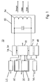
- the encoder arrangement shown as a block diagram in FIG. 1 10 includes a data transmitter 14, which also simultaneously as Energy transmitter 34 is used, a data receiver 16, a memory 20, a keyboard 44, a display 46, a control unit 18, an energy source 48 and one at the same time Transmitting and receiving antenna resonant circuit 50.
- About the oscillating circuit 50 becomes data and energy for the receiving device 12 transmitted and from the receiving device 12 received data.
- Control of the data transmitter 14 and data receiver 16 and the memory 20, the display and the keyboard is done by the control unit 18.
- Die Control unit 18 also takes on the function of a Decoder 40 for checking the validity of received Data.
- the memory 20 is divided into a rewritable one Area and a non-writable or one-time writable Area in which an exclusive identification number of the Encoder arrangement 10 is stored.
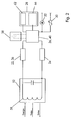
- the receiving device shown in Fig. 2 as a block diagram 12 partially has similar functional blocks as that
- the encoder arrangement 10 described above is also the case with the receiving device 12 a data transmitter 24, a data receiver 22, a memory 28, a control unit 26 and a simultaneously resonant circuit 52 serving as transmitting and receiving antenna available.
- the data receiver 22 simultaneously forms one Energy receiver 36.
- Via the resonant circuit 52 data transferred to the encoder arrangement 10 and from the encoder arrangement 10 data and energy received.
- the control of the Data transmitter 24 and data receiver 22 and the memory 28 is carried out by the control unit 26
- Control unit 26 the function of a decoder 42 for testing the validity of received data.
- the memory 28 is divided into a repeatable area and an area that cannot be written or written once, in which a exclusive identification number of the receiving device 12 is stored is.
- a temporary energy store 38 to be available.
- the receiving device 12 has an actuator 32 and a sensor 30 connected.
- the actuator 32 and the sensor 30 are controlled by the control unit 26.
- the energy supply of the actuator 32 and sensor 30 takes place wirelessly from the Encoder arrangement 10 for the receiving device 12.
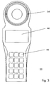
- FIG. 3 shows an embodiment of a transmitter arrangement 10
- Function blocks described in Fig. 1 are here in one shared housing. It is externally visible Display 46 and keyboard 44. Furthermore, an area can be seen, in which the coil 54 of the resonant circuit 50 is accommodated is. In this case, the coil 54 is dimensioned such that also the energy for operating the sensor 30 and the actuator 32 Receiving device 12 can be transmitted.
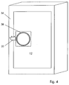
- the receiving device 12 comprises the functional blocks from Fig. 2 and further an actuator 32 and a sensor 30.
- Der Sensor 30 can be designed as a temperature sensor, for example be the temperature inside a container 56 or Detect container and monitor from the outside.
- Actuator 32 is designed here as a motor bolt to mechanically lock the door to lock and unlock without a mechanical Key is needed.
- the coil 58 of the resonant circuit 52 can be seen, which is approximately the same size as the coil 54 in the transmitter arrangement 10 is matched. This is an optimal one Coupling and thus maximum energy transfer guaranteed.
- the application described here for installing the receiving device 12 in a container 56 is particularly predestined for the invention, since the receiving device 12, with exceptions, not from the public low-voltage network can be supplied with energy and with battery operation there is no guarantee that necessary maintenance work will be carried out be carried out on time.
- both the energy for operating the functional blocks of the receiving device 12 as well as for operating the sensor 30 and the actuator 32 wirelessly transfer.
- the lock can therefore only from one encoder arrangement 10, which is authorized to do so.
- a mechanical one Opening without using the transmitter assembly 10 is not possible or only by destroying container 56. This results in a high degree of security against manipulation.
- the transmitter arrangement 10 and the receiving device 12 each other's authentication data through a test algorithm changed and retransmitted. Because the test algorithm both devices are known, the validity of the Authentication data can be checked without it being intercepted succeeds in decrypting the authentication data. The authentication data is updated with every new transmission changed.
- the test algorithm can be influenced by the identification numbers will. Only when the devices connected to each other have determined the validity of the identification data, the memory 28 as well as the actuator 32 and the sensor 30 released by the control unit 26 of the receiving device 12.
Landscapes
- Engineering & Computer Science (AREA)
- Theoretical Computer Science (AREA)
- Computer Hardware Design (AREA)
- Microelectronics & Electronic Packaging (AREA)
- Physics & Mathematics (AREA)
- General Physics & Mathematics (AREA)
- Computer Networks & Wireless Communication (AREA)
- Artificial Intelligence (AREA)
- Computer Vision & Pattern Recognition (AREA)
- Lock And Its Accessories (AREA)
- Mobile Radio Communication Systems (AREA)
- Arrangements For Transmission Of Measured Signals (AREA)
- Near-Field Transmission Systems (AREA)
- Selective Calling Equipment (AREA)
Abstract
Description
Die Erfindung betrifft ein drahtloses Datenübertragungssystem nach dem Oberbegriff des Anspruchs 1.The invention relates to a wireless data transmission system according to the preamble of claim 1.
Aus der DE PS 40 03 410 C2 ist ein Datenübertragungssystem bekannt. Dieses bekannte System umfaßt eine Schreibleseeinheit mit einem Datensender, einem Datenempfänger, einem Speicher und einer Eingabeeinheit sowie ein Detektierplättchen mit einem Datensender, einem Datenempfänger und einem Speicher. Der Datensender der Schreibleseeinheit ist gleichzeitig als Energiesender ausgebildet und überträgt die zum Betrieb des Detektierplättchens nötige Energie zu einem Energieempfänger auf dem Detektierplättchen.A data transmission system is known from DE PS 40 03 410 C2 known. This known system comprises a read / write unit with a data transmitter, a data receiver, a memory and an input unit and a detection plate with a data transmitter, a data receiver and a memory. The data transmitter of the read / write unit is simultaneous trained as an energy transmitter and transmits it to operation of the detection plate required energy to an energy receiver on the detection plate.
Das Detektierplättchen und die Schreibleseeinheit können beide mobil oder eines der beiden Komponenten kann mobil und das andere stationär betrieben werden. Bei Einsatz in einer Zugangskontrolle kann die Schreibleseeinheit stationär angeordnet und mit einem Türöffner verbunden sein. Die Energieversorgung der Schreibleseeinheit und des Türöffners erfolgt aus dem Niederspannungsnetz. Die Detektierplättchen werden von zugangsberechtigten Personen getragen. Sobald ein Detektierplättchen in die Nähe einer Antenne der Schreibleseeinheit gebracht wird, werden deren Daten von der Schreibleseeinheit gelesen und auf Gültigkeit überprüft. Bei Gültigkeit wird der Türöffner freigegeben. Durch Beschreiben des Speichers des Detektierplättchens können Daten und damit Zugangsberechtigungen geändert werden.The detection plate and the read / write unit can both mobile or one of the two components can be mobile and that others are operated stationary. When used in an access control the read / write unit can be arranged stationary and be connected to a door opener. The energy supply the read / write unit and the door opener are off the low-voltage network. The detection plates are from authorized persons. As soon as a detection plate near an antenna of the read / write unit is brought, their data from the read / write unit read and checked for validity. If valid, the Door release released. By writing to the memory of the Detection plates can contain data and therefore access authorizations be changed.
Bei Ausfall der Energieversorgung ist das Datenübertragungssystem außer Betrieb. Die Tür kann dann nur noch durch einen konventionellen mechanischen Schlüssel geöffnet werden, was aber die Sicherheit gegen Manipulationsmöglichkeiten mindert. Durch Batteriebetrieb oder Pufferbetrieb können bei regelmäßiger Wartung zwar die Folgen plötzlicher, unerwarteter Energieversorgungsausfälle beseitigt werden, bei mangelnder Wartung ist diese Sicherheit gegen Netzausfälle aber wieder verloren. If the power supply fails, the data transmission system out of order. The door can only be opened by one conventional mechanical key can be opened what but reduces security against manipulation possibilities. By battery operation or buffer operation with regular Maintenance is the result of sudden, unexpected power failures be eliminated in the event of poor maintenance this security against power failures is lost again.
Der Erfindung liegt die Aufgabe zugrunde, bei einem drahtlosen Datenübertragungssystem die Funktionssicherheit und Manipulationssicherheit zu verbessern.The invention has for its object in a wireless Data transmission system the functional security and manipulation security to improve.
Diese Aufgabe wird bei einem drahtlosen Datenübertragungssystem nach dem Oberbegriff des Anspruchs 1 durch die im kennzeichnenden Teil angegebenen Merkmale gelöst. Weiterbildungen und vorteilhafte Ausgestaltungen der Erfindung ergeben sich aus den Unteransprüchen.This task is accomplished with a wireless data transmission system according to the preamble of claim 1 by the in the characterizing Part specified features solved. Training and advantageous embodiments of the invention result from the subclaims.
Bei der erfindungsgemäßen Lösung kann die Empfangseinrichtung manipulationssicher eingebaut oder untergebracht werden, da die Energieversorgung aller Komponenten, also einschließlich des Sensors und/oder Aktors auf drahtlosem Weg erfolgt und damit stets von außen sichergestellt werden kann. Die Funktionszuverlässigkeit ist dadurch so hoch, daß Notmaßnahmen zur Überbrückung von Störungen, die gleichseitig aber auch die Manipulationssicherheit beeinträchtigen würden, entfallen können.In the solution according to the invention, the receiving device can tamper-proof installed or housed, because the energy supply of all components, including of the sensor and / or actuator takes place wirelessly and so that it can always be ensured from the outside. The functional reliability is so high that emergency measures for Bridging disturbances, which are equilateral but also those Manipulation security would be compromised can.
Für die Energieversorgung des Sensors und/oder Aktors bieten sich mehrere Möglichkeiten. So kann der Energieempfänger einen temporären Energiespeicher umfassen, der durch Energieübertragung von der Geberanordnung zur Empfangseinrichtung aufladbar ist und kurzzeitig die Energieversorgung des Sensors und/oder Aktors übernimmt.Offer for the energy supply of the sensor and / or actuator yourself several options. So the energy recipient can include temporary energy storage by energy transfer from the transmitter arrangement to the receiving device is rechargeable and briefly the energy supply of the sensor and / or actuator takes over.
Bei dieser Lösung muß die Energieübertragung nicht gleichzeitig mit dem Betrieb des Sensors und/oder Aktors erfolgen. Außerdem besteht die Möglichkeit, bei einem geringen durchschnittlichen Energiefluß zum Energieempfänger kurzzeitig erhöhten Energiebedarf zu decken.With this solution, the energy transfer does not have to be simultaneous with the operation of the sensor and / or actuator. Furthermore there is a possibility at a low average Briefly increase the energy flow to the energy receiver To cover energy needs.
Andererseits kann die Energieversorgung des Sensors und/oder Aktors ausschließlich durch drahtlose Energieübertragung während dessen Betrieb erfolgen.On the other hand, the energy supply to the sensor and / or Actuator only through wireless energy transfer during its operation take place.
Diese Lösung kommt ohne Energiespeicher aus, was räumliche Vorzüge bietet. Allerdings muß der drahtlose Energiefluß auch den Spitzenbedarf beim Betrieb des Sensors und/oder Aktors decken können, so daß der Eneregiesender entsprechend leistungsstark ausgelegt sein muß. This solution does not require energy storage, which is spatial Offers advantages. However, the wireless energy flow must also the peak demand when operating the sensor and / or actuator can cover, so that the energy transmitter accordingly powerful must be designed.
Alternativ kann als Kombination beider vorgenannter Lösungen auch vorgesehen werden, daß die Energieversorgung des Sensors und/oder Aktors sowohl durch drahtlose Energieübertragung während dessen Betrieb als auch durch Pufferung durch einen temporären Energiespeichers erfolgt, der durch drahtlose Energieübertragung aufladbar ist.Alternatively, a combination of both of the above solutions also be provided that the power supply to the sensor and / or actuator both by wireless energy transmission during its operation as well as by buffering by a temporary energy storage is done by wireless Energy transfer is rechargeable.
Bei dieser Lösung kann der Energiespeicher kleiner als bei der erstgenannten Variante bemessen werden, da er nur zur Überbrückung von Energiespitzen benötigt wird.With this solution, the energy store can be smaller than in the first-mentioned variant, because it is only for Bridging energy peaks is needed.
Der Energiesender kann zusammen mit dem Datensender und Datenempfänger der Geberanordnung vereint oder als gesondertes Gerät ausgebildet sein.The energy transmitter can work together with the data transmitter and data receiver the encoder arrangement combined or as a separate Device be trained.
Je nach erforderlicher Sendeleistung des Energiesenders und dem Umstand, ob eine drahtlose Energieübertragung generell oder nur bei Ausfall der regulären Energieversorgung vorgenommen werden soll, kann die eine oder andere Variante gewählt werden. Wenn der Energiesender mit dem Datensender und Datenempfänger der Geberanordnung vereint wird, erhöht sich dessen Gewicht und Baugröße, während im anderen Fall zwar im Normalfall die Handhabung der Geberanordnung einfacher ist, bei Ausfall der Energieversorgung aber ein zusätzliches Gerät benötigt wird.Depending on the required transmission power of the energy transmitter and whether wireless energy transmission in general or only if the regular energy supply fails one or the other variant can be selected will. If the energy transmitter with the data transmitter and Data receiver of the encoder arrangement is combined, increases its weight and size, while in the other case in Normally the handling of the encoder arrangement is easier, if the power supply fails, an additional device is needed.
Die Empfangseinrichtung kann einen Dekoder umfassen, welcher auf Anforderung der Steuereinheit der Empfangseinrichtung von der Geberanordnung gesendete Autentifikationsdaten auswertet und bei Gültigkeit der Autentifikationsdaten den Speicher und/oder Sensor und/oder Aktor freigibt.The receiving device can comprise a decoder, which at the request of the control unit of the receiving device from evaluates the authentication data sent to the transmitter arrangement and if the authentication data is valid, the memory and / or sensor and / or actuator releases.
Diese Maßnahme erhöht die Sicherheit gegen Manipulationen, indem unter Gebereinheiten, die das Übertragungsprotokoll für die Datenübertragung zur Empfangseinrichtung und zurück beherrschen, selektiv Berechtigungen vergeben werden können, die von der Empfangseinrichtung abgefragt werden. Die Berechtigungen lassen sich durch Ändern der Speicherinhalte ebenfalls ändern.This measure increases security against manipulation, by taking encoder units that the transmission protocol for master the data transmission to the receiving device and back, permissions can be assigned selectively, which are queried by the receiving device. The permissions can also be changed by changing the memory contents to change.
Gemäß einer Weiterbildung können sowohl im Speicher der Geberanordnung als auch im Speicher der Empfangseinrichtung Autentifikationsdaten abgelegt sein. Ferner können sowohl in der Geberanordnung als auch in der Empfangseinrichtung Dekoder vorgesehen sein, mittels der die auf Anforderung gegenseitig übermittelten Autentifikationsdaten auf Gültigkeit überprüfbar sind. Es kann ein bidirektionaler Datenaustausch zwischen Geberanordnung und Empfangseinrichtung stattfinden und erst bei Gültigkeit beider Autentifikationsdaten der Speicher der Empfangseinrichtung und/oder der Sensor und/oder der Aktors freigegeben werden.According to a further development, the encoder arrangement can be stored in the memory as well as in the memory of the receiving device Authentication data must be stored. Furthermore, both in the encoder arrangement as well as in the receiving device decoder be provided by means of which the other on request transmitted authentication data for validity are verifiable. There can be a bidirectional data exchange take place between the encoder arrangement and the receiving device and only if both authentication data of the Memory of the receiving device and / or the sensor and / or the actuator are released.
Die Manipulationssicherheit wird hierdurch nochmals gesteigert. Wenn der Versuch unternommen wird, die Autentifikationsdaten durch "Abhören" der Datenkommunikation zu identifizieren und so den Kode zu entschlüsseln, wird dies durch die Zuordnungsschwierigkeit mehrerer Autentifikationsdaten erheblich erschwert.This increases the security against manipulation. If the attempt is made, the authentication data by "listening" to the data communication and so to decode the code, this is done by the Assignment difficulty of several authentication data considerably difficult.
Eine weitere Steigerung der Manipulationssicherheit ergibt sich, wenn in wenigstens einem der Speicher der Geberanordnung oder der Empfangseinrichtung variable Autentifikationsdaten und wenigstens im jeweils anderen Speicher der Empfangseinrichtung oder der Geberanordnung ein Prüfalgorithmus abgelegt sind, mittels eines dem Speicher für die Autentifikationsdaten zugeordneten Dekoders die hin- und mittels des Prüfalgorithmus verändert rückübermittelten Autentifikationsdaten auf Gültigkeit überprüft werden und erst bei Gültigkeit beider Autentifikationsdaten der Speicher der Empfangseinrichtung und/oder der Sensor und/oder der Aktors freigegeben werden. Der Prüfalgorithmus kann exklusive Identnummern der zur Kommunikation berechtigten Partner aus Geberanordnungen und Empfangseinheiten einbeziehen.A further increase in security against manipulation results itself if in at least one of the memories of the transmitter arrangement or variable identification data of the receiving device and at least in the other memory of the receiving device or the encoder arrangement a test algorithm are stored by means of a memory for the authentication data assigned decoder to and by means of The test algorithm changes the returned authentication data be checked for validity and only when valid both authentication data of the memory of the receiving device and / or the sensor and / or the actuator released will. The test algorithm can contain exclusive identification numbers of the Partner authorized to communicate from donor orders and include receiving units.
Da die übertragenen Autentifikationsdaten ständig verändert werden und der Kodeschlüssel im gespeicherten, aber nicht übertragenen Prüfalgorithmus steckt, würde ein "Abhören" der Datenkommunikation nur einiger weniger Datenübertragungsaktionen nicht mehr zum Entschlüsseln des Kodes ausreichen.Because the transmitted authentication data is constantly changing and the code key in the saved, but not transmitted test algorithm, a "listening" of the Data communication of just a few data transfer actions is no longer sufficient to decrypt the code.
Vorzugsweise werden im Speicher der Geberanordnung und/oder der Empfangseinrichtung Protokolldaten der erfolgten Datenkommunikation und Autentifikationsdaten abgelegt. So kann die Geberanordnung protokollieren, welche Empfangsvorrichtungen bedient wurden und die Empfangsvorrichtung kann kann protokollieren, welche Geber den Autentifikationsprozeß durchgeführt haben. The transmitter arrangement and / or are preferably stored in the memory the receiving device protocol data of the data communication and authentication data stored. So it can Transmitter arrangement log which receiving devices have been operated and the receiving device can log which donors carried out the authentication process to have.
Hierdurch lassen sich Datenübertragungsaktionen rückverfolgen und so Manipulationsversuche aber auch Mißbrauch mit berechtigten Geräten aufdecken.This enables data transmission actions to be traced and so manipulation attempts but also abuse with justified Uncover devices.
Nachfolgend wird die Erfindung anhand der Zeichnung näher erläutert.The invention is explained in more detail below with reference to the drawing.
In der Zeichnung zeigen:
- Fig. 1
- ein Blockschaltbild einer Geberanordnung,
- Fig. 2
- ein Blockschaltbild einer Empfangseinrichtung,
- Fig. 3
- eine Ausgestaltung einer Geberanordnung und
- Fig. 4
- eine Ausgestaltung einer Empfangseinrichtung.
- Fig. 1
- 2 shows a block diagram of an encoder arrangement,
- Fig. 2
- 2 shows a block diagram of a receiving device,
- Fig. 3
- an embodiment of an encoder arrangement and
- Fig. 4
- an embodiment of a receiving device.
Die in Fig. 1 als Blockschaltbild dargestellte Geberanordnung
10 umfaßt einen Datensender 14, der auch gleichzeitig als
Energiesender 34 dient, einen Datenempfänger 16, einen Speicher
20, eine Tastatur 44, eine Anzeige 46, eine Steuereinheit
18, eine Energiequelle 48 und einen gleichzeitig als
Sende- und Empfangsantenne dienenden Schwingkreis 50. Über
den Schwingkreis 50 werden Daten und Energie zur Empfangseinrichtung
12 übertragen und von der Empfangseinrichtung 12
stammende Daten empfangen. Die Steuerung des Datensenders 14
und Datenempfängers 16 sowie des Speichers 20, der Anzeige
und der Tastatur erfolgt durch die Steuereinheit 18. Die
Steuereinheit 18 übernimmt auch gleichzeitig die Funktion eines
Dekoders 40 zur Prüfung der Gültigkeit von empfangenen
Daten. Der Speicher 20 ist unterteilt in einen wiederholt beschreibbaren
Bereich und einen nicht- oder einmalig beschreibbaren
Bereich, in dem eine exklusive Identnummer der
Geberanordnung 10 gespeichert ist.The encoder arrangement shown as a block diagram in FIG. 1
10 includes a data transmitter 14, which also simultaneously as
Energy transmitter 34 is used, a
Die in Fig. 2 als Blockschaltbild dargestellte Empfangseinrichtung
12 hat teilweise ähnliche Funktionsblöcke wie die
vorbeschriebene Geberanordnung 10. So ist auch bei der Empfangseinrichtung
12 ein Datensender 24, ein Datenempfänger
22, ein Speicher 28, eine Steuereinheit 26 und ein gleichzeitig
als Sende- und Empfangsantenne dienender Schwingkreis 52
vorhanden. Der Datenempfänger 22 bildet gleichzeitig einen
Energieempfänger 36. Über den Schwingkreis 52 werden Daten
zur Geberanordnung 10 übertragen und von der Geberanordnung
10 stammende Daten sowie Energie empfangen. Die Steuerung des
Datensenders 24 und Datenempfängers 22 sowie des Speichers 28
erfolgt durch die Steuereinheit 26. Ebenso übernimmt die
Steuereinheit 26 die Funktion eines Dekoders 42 zur Prüfung
der Gültigkeit von empfangenen Daten. Auch der Speicher 28
ist unterteilt in einen wiederholt beschreibbaren Bereich und
einen nicht- oder einmalig beschreibbaren Bereich, in dem eine
exklusive Identnummer der Empfangseinrichtung 12 gespeichert
ist. Ergänzend kann ein temporärer Energiespeicher 38
vorhanden sein.The receiving device shown in Fig. 2 as a block diagram
12 partially has similar functional blocks as that
The
Zusätzlich ist die Empfangseinrichtung 12 mit einem Aktor 32
und einem Sensor 30 verbunden. Der Aktor 32 und der Sensor 30
werden von der Steuereinheit 26 gesteuert. Die Energieversorgung
des Aktors 32 und Sensors 30 erfolgt drahtlos von der
Geberanordnung 10 zur Empfangseinrichtung 12. In addition, the receiving
Fig. 3 zeigt eine Ausgestaltung einer Geberanordnung 10. Die
in Fig. 1 beschriebenen Funktionsblöcke sind hier in einem
gemeinsamen Gehäuse untergebracht. Äußerlich sichtbar ist die
Anzeige 46 sowie die Tastatur 44. Ferner ist ein Bereich erkennbar,
in dem die Spule 54 des Schwingkreises 50 untergebracht
ist. Die Spule 54 ist in diesem Fall so bemessen, daß
auch die Energie zum Betrieb des Sensors 30 und Aktors 32 der
Empfangseinrichtung 12 übertragen werden kann.3 shows an embodiment of a
Fig. 4 zeigt eine Ausgestaltung einer Empfangseinrichtung 12,
die hier manipulationssicher in einem Container 56 eingebaut
ist. Die Empfangseinrichtung 12 umfaßt die Funktionsblöcke
aus Fig. 2 und ferner einen Aktor 32 und einen Sensor 30. Der
Sensor 30 kann zum Beispiel als Temperatursensor ausgebildet
sein, um die Temperatur im Inneren eines Containers 56 oder
Behälters erfassen und von außen überwachen zu können. Der
Aktor 32 ist hier als Motorriegel ausgebildet, um die Tür mechanisch
zu ver- und entriegeln, ohne daß hierfür ein mechanischer
Schlüssel benötigt wird. Als Teil der Empfangseinrichtung
12 ist die Spule 58 des Schwingkreises 52 erkennbar,
die in ihrer Größe etwa auf die Größe der Spule 54 in der Geberanordnung
10 abgestimmt ist. Auf diese Weise ist eine optimale
Kopplung und damit eine maximale Energieübertragung
gewährleistet.4 shows an embodiment of a receiving
Der hier beschriebene Anwendungsfall des Einbaus der Empfangseinrichtung
12 in einen Container 56 ist besonders prädestiniert
für die Erfindung, da die Empfangseinrichtung 12,
von Ausnahmen abgesehen, nicht vom öffentlichen Niederspannungsnetz
mit Energie versorgt werden kann und bei Batteriebetrieb
keine Gewähr besteht, daß nötige Wartungsarbeiten
termingerecht durchgeführt werden.The application described here for installing the receiving
Bei der erfindungsgemäßen Ausgestaltung wird sowohl die Energie
zu Betrieb der Funktionsblöcke der Empfangseinrichtung 12
als auch zum Betrieb des Sensors 30 und des Aktors 32 drahtlos
übertragen. Das Schloß kann somit nur von einer Geberanordnung
10 geöffnet werden, die dazu berechtigt ist. Eine mechanische
Öffnung ohne Benutzung der Geberanordnung 10 ist
nicht möglich oder nur durch Zerstörung des Containers 56.
Dadurch ergibt sich eine hohe Sicherheit geben Manipulationen. In the embodiment according to the invention, both the energy
for operating the functional blocks of the receiving
Zum Schutz vor Manipulationen mit nicht freigegebenen Geberanordnungen, die aber das benutzte Übertragungsprotokoll beherrschen, kann folgendermaßen verfahren werden.To protect against manipulation with non-approved encoder arrangements, but who master the transmission protocol used, can be done as follows.
Die exklusiven Identnummern der Geberanordnungen und Empfangseinrichtungen,
die in einem nichtbeschreibbaren oder nur
einmalig beschreibbaren Speicherbereich 60; 62 abgelegt sind,
dienen zur Festlegung, welche Geberanordnungen und Empfangseinrichtungen
als Partner zur gegenseitigen Kommunikation zugelassen
sind. Dazu werden die Identnummern der Zulässigen
Partner im wiederbeschreibbaren Speicherbereich 64; 66 der
anderen Partner abgelegt. Wenn die Geberanordnung 10 elektromagnetisch
mit einer Empfangseinrichtung 12 gekoppelt wird
und die Funktionsblöcke der Empfangseinrichtung 12 mit Energie
versorgt werden und in Betrieb gehen, erfolgt zunächst
ein Austausch von Autentifikationsdaten.The exclusive ID numbers of the encoder arrangements and receiving devices,
the in a non-writable or just
Bei einem besonders manipulationssicheren Verfahren übermitteln
die Geberanordnung 10 und die Empfangseinrichtung 12
einander Autentifikationsdaten, die durch einen Prüfalgorithmus
verändert und rückübertragen werden. Da der Prüfalgorithmus
beiden Geräten bekannt ist, kann so die Gültigkeit der
Autentifikationsdaten überprüft werden, ohne daß es durch Abhören
gelingt, die Autentifikationsdaten zu entschlüsseln.
Die Autentifikationsdaten werden bei jeder neuen Übertragung
geändert. Der Prüfalgorithmus kann durch die Identnummern beeinflußt
werden. Erst wenn die miteinander gekoppelten Geräte
die Gültigkeit der Autentifikationsdaten ermittelt haben,
wird der Speicher 28 sowie der Aktor 32 und der Sensor 30
durch die Steuereinheit 26 der Empfangseinrichtung 12 freigegeben.Transmit in a particularly tamper-proof process
the
Claims (9)
Applications Claiming Priority (2)
| Application Number | Priority Date | Filing Date | Title |
|---|---|---|---|
| DE19719562 | 1997-05-09 | ||
| DE19719562A DE19719562A1 (en) | 1997-05-09 | 1997-05-09 | Wireless data transmission system |
Publications (3)
| Publication Number | Publication Date |
|---|---|
| EP0877331A2 true EP0877331A2 (en) | 1998-11-11 |
| EP0877331A3 EP0877331A3 (en) | 1999-10-20 |
| EP0877331B1 EP0877331B1 (en) | 2003-08-20 |
Family
ID=29265469
Family Applications (2)
| Application Number | Title | Priority Date | Filing Date |
|---|---|---|---|
| EP98107287A Expired - Lifetime EP0877333B1 (en) | 1997-05-09 | 1998-04-22 | Apparatus for wireless transfer of energy and execution of an action |
| EP98107483A Expired - Lifetime EP0877331B1 (en) | 1997-05-09 | 1998-04-24 | Wireless communicationsystem |
Family Applications Before (1)
| Application Number | Title | Priority Date | Filing Date |
|---|---|---|---|
| EP98107287A Expired - Lifetime EP0877333B1 (en) | 1997-05-09 | 1998-04-22 | Apparatus for wireless transfer of energy and execution of an action |
Country Status (2)
| Country | Link |
|---|---|
| EP (2) | EP0877333B1 (en) |
| DE (3) | DE19719562A1 (en) |
Cited By (6)
| Publication number | Priority date | Publication date | Assignee | Title |
|---|---|---|---|---|
| WO2001082447A1 (en) * | 2000-04-20 | 2001-11-01 | Abb Research Ltd. | Sensor with a wireless power supply |
| WO2005078667A1 (en) * | 2004-02-13 | 2005-08-25 | Melexis Nv | Locking device |
| WO2007079332A2 (en) * | 2005-12-14 | 2007-07-12 | Checkpoint Systems, Inc. | Systems and methods for providing universal security for items |
| WO2008043192A2 (en) * | 2006-10-09 | 2008-04-17 | Legic Identsystems Ag | Device and method for operating a read/write device |
| EP2051189A1 (en) * | 2007-10-18 | 2009-04-22 | Siemens Aktiengesellschaft | Device for electronic identification of items |
| EP2425516B1 (en) | 2009-04-30 | 2015-12-23 | Assa Abloy Ab | External power supply system for a lock comprising nfc-type contactless communication means |
Families Citing this family (8)
| Publication number | Priority date | Publication date | Assignee | Title |
|---|---|---|---|---|
| DE59913632D1 (en) | 1999-01-08 | 2006-08-10 | Anatoli Stobbe | Security system, transponder and receiving device |
| DE10233597A1 (en) * | 2002-07-24 | 2004-02-05 | Brühn, Xenia | Car or door radio keyless entry system has mobile phone linked alarm warning for unusual use with encrypted preamble to identify correct user |
| DE10348569A1 (en) * | 2003-10-20 | 2005-05-25 | Giesecke & Devrient Gmbh | Device for triggering actuator, e.g. for electronic lock cylinder, has receiver unit via which energy for charging energy storage device can be delivered; energy fed to receiver unit is converted into voltage |
| DE102005036290B4 (en) * | 2005-08-02 | 2009-04-30 | Gebrüder Frei GmbH & Co. KG | operating system |
| DE102009043571B3 (en) * | 2009-09-30 | 2011-02-17 | Festo Ag & Co. Kg | Fluid-electrical device, has switching device consisting of electrical operatable switch arrangement that is switched in supply line between energy storage and electrical consumer and controllable by electrical switch |
| DE102012102007A1 (en) | 2012-03-09 | 2013-09-12 | Infineon Technologies Ag | A power supply device for supplying a voltage from an electromagnetic field |
| DE102014219088A1 (en) * | 2014-09-22 | 2016-03-24 | Siemens Aktiengesellschaft | Arrangement and a method for switching a switching path by means of a switching device |
| DE102014219089A1 (en) * | 2014-09-22 | 2016-03-24 | Siemens Aktiengesellschaft | Arrangement and method for switching switching paths by means of switching devices |
Citations (3)
| Publication number | Priority date | Publication date | Assignee | Title |
|---|---|---|---|---|
| EP0441237A1 (en) * | 1990-02-05 | 1991-08-14 | Anatoli Stobbe | Portable detecting plate which is programmable by fields |
| EP0634729A2 (en) * | 1993-07-14 | 1995-01-18 | Philips Patentverwaltung GmbH | Device for date exchange |
| JPH10307898A (en) * | 1997-05-09 | 1998-11-17 | Toppan Printing Co Ltd | Charge type non-contact ic card system |
Family Cites Families (3)
| Publication number | Priority date | Publication date | Assignee | Title |
|---|---|---|---|---|
| JPS60119873A (en) * | 1983-11-29 | 1985-06-27 | 日産自動車株式会社 | Locking controller for vehicle |
| US4829296A (en) * | 1986-04-30 | 1989-05-09 | Carey S. Clark | Electronic lock system |
| US5300875A (en) * | 1992-06-08 | 1994-04-05 | Micron Technology, Inc. | Passive (non-contact) recharging of secondary battery cell(s) powering RFID transponder tags |
-
1997
- 1997-05-09 DE DE19719562A patent/DE19719562A1/en not_active Withdrawn
-
1998
- 1998-04-22 DE DE59812235T patent/DE59812235D1/en not_active Expired - Lifetime
- 1998-04-22 EP EP98107287A patent/EP0877333B1/en not_active Expired - Lifetime
- 1998-04-24 DE DE59809318T patent/DE59809318D1/en not_active Expired - Lifetime
- 1998-04-24 EP EP98107483A patent/EP0877331B1/en not_active Expired - Lifetime
Patent Citations (3)
| Publication number | Priority date | Publication date | Assignee | Title |
|---|---|---|---|---|
| EP0441237A1 (en) * | 1990-02-05 | 1991-08-14 | Anatoli Stobbe | Portable detecting plate which is programmable by fields |
| EP0634729A2 (en) * | 1993-07-14 | 1995-01-18 | Philips Patentverwaltung GmbH | Device for date exchange |
| JPH10307898A (en) * | 1997-05-09 | 1998-11-17 | Toppan Printing Co Ltd | Charge type non-contact ic card system |
Non-Patent Citations (1)
| Title |
|---|
| PATENT ABSTRACTS OF JAPAN vol. 099, no. 002, 26. Februar 1999 (1999-02-26) & JP 10 307898 A (TOPPAN PRINTING CO LTD), 17. November 1998 (1998-11-17) * |
Cited By (13)
| Publication number | Priority date | Publication date | Assignee | Title |
|---|---|---|---|---|
| WO2001082447A1 (en) * | 2000-04-20 | 2001-11-01 | Abb Research Ltd. | Sensor with a wireless power supply |
| WO2005078667A1 (en) * | 2004-02-13 | 2005-08-25 | Melexis Nv | Locking device |
| WO2007079332A2 (en) * | 2005-12-14 | 2007-07-12 | Checkpoint Systems, Inc. | Systems and methods for providing universal security for items |
| WO2007079332A3 (en) * | 2005-12-14 | 2007-09-20 | Checkpoint Systems Inc | Systems and methods for providing universal security for items |
| US8544742B2 (en) | 2006-10-09 | 2013-10-01 | Legic Idenstsystems Ag | Device and method for operating a read/write device |
| WO2008043192A3 (en) * | 2006-10-09 | 2008-06-05 | Legic Identsystems Ag | Device and method for operating a read/write device |
| JP2010506274A (en) * | 2006-10-09 | 2010-02-25 | レジック・アイデントシステムズ・アクチェンゲゼルシャフト | Device and method for operating a read / write device |
| WO2008043192A2 (en) * | 2006-10-09 | 2008-04-17 | Legic Identsystems Ag | Device and method for operating a read/write device |
| CN101523407B (en) * | 2006-10-09 | 2014-11-26 | 励智识别技术有限公司 | Device and method for operating a read/write device |
| EP2051189A1 (en) * | 2007-10-18 | 2009-04-22 | Siemens Aktiengesellschaft | Device for electronic identification of items |
| US7970484B2 (en) | 2007-10-18 | 2011-06-28 | Siemens Aktiengesellschaft | Method of controlling a production process |
| EP2425516B1 (en) | 2009-04-30 | 2015-12-23 | Assa Abloy Ab | External power supply system for a lock comprising nfc-type contactless communication means |
| EP2425516B2 (en) † | 2009-04-30 | 2019-09-18 | Assa Abloy Ab | External power supply system for a lock comprising nfc-type contactless communication means |
Also Published As
| Publication number | Publication date |
|---|---|
| EP0877331B1 (en) | 2003-08-20 |
| EP0877333A2 (en) | 1998-11-11 |
| EP0877333B1 (en) | 2004-11-10 |
| DE59812235D1 (en) | 2004-12-16 |
| EP0877331A3 (en) | 1999-10-20 |
| DE59809318D1 (en) | 2003-09-25 |
| DE19719562A1 (en) | 1998-11-19 |
| EP0877333A3 (en) | 2002-01-16 |
Similar Documents
| Publication | Publication Date | Title |
|---|---|---|
| EP0877331B1 (en) | Wireless communicationsystem | |
| DE3905651C2 (en) | ||
| EP0788946B1 (en) | Method and apparatus for programming operational data into automotive parts | |
| AT506344B1 (en) | METHOD AND DEVICE FOR CONTROLLING THE ACCESS CONTROL | |
| EP1012430A1 (en) | Process and device for controlling the closure of locks | |
| DE19502373C2 (en) | Anti-theft method for motor-driven motor vehicles | |
| DE3918052C1 (en) | ||
| DE69519616T2 (en) | Portable communication device and an IC card therefor | |
| EP1205885A2 (en) | Electronically codable lock system | |
| EP2689401A1 (en) | Method for operating a cash box with customer-specific keys | |
| DE4433499C2 (en) | Electronic anti-theft protection system for a motor vehicle | |
| EP3567557A1 (en) | Locking system | |
| EP1784756B1 (en) | Method and security system for the secure and unambiguous coding of a security module | |
| EP0891607B1 (en) | Method for operating a remote-control device and a remote-control device | |
| EP2584539A1 (en) | Method for configuring an electromechanical lock | |
| EP0825316B1 (en) | Method and system for writing an information key | |
| DE10152349B4 (en) | safety device | |
| EP0596401B1 (en) | Method to individualize and synchronize a control apparatus | |
| EP1277632A2 (en) | Remote operation method for the locking and/or unlocking of a vehicle | |
| EP0879160B2 (en) | Motor vehicle anti-theft device and method | |
| DE10202321B4 (en) | System and method for electronic authentication | |
| EP1389257B1 (en) | Safety system for boxes | |
| DE10044658A1 (en) | System and environmental conditions monitoring and registering device has communications units for coupling stationary control centre to mobile or stationary devices allowing remote monitoring | |
| EP2110793A2 (en) | Self-service device | |
| DE4236863A1 (en) | Vehicle active-key programming for central door-locking system - involves encoding key with unique fixed and variable component data-set for subsequent transfer to, and matching of, lock control unit. |
Legal Events
| Date | Code | Title | Description |
|---|---|---|---|
| PUAI | Public reference made under article 153(3) epc to a published international application that has entered the european phase |
Free format text: ORIGINAL CODE: 0009012 |
|
| AK | Designated contracting states |
Kind code of ref document: A2 Designated state(s): DE FR GB |
|
| AX | Request for extension of the european patent |
Free format text: AL;LT;LV;MK;RO;SI |
|
| PUAL | Search report despatched |
Free format text: ORIGINAL CODE: 0009013 |
|
| AK | Designated contracting states |
Kind code of ref document: A3 Designated state(s): AT BE CH CY DE DK ES FI FR GB GR IE IT LI LU MC NL PT SE |
|
| AX | Request for extension of the european patent |
Free format text: AL;LT;LV;MK;RO;SI |
|
| 17P | Request for examination filed |
Effective date: 19991231 |
|
| AKX | Designation fees paid |
Free format text: DE FR GB |
|
| GRAH | Despatch of communication of intention to grant a patent |
Free format text: ORIGINAL CODE: EPIDOS IGRA |
|
| GRAH | Despatch of communication of intention to grant a patent |
Free format text: ORIGINAL CODE: EPIDOS IGRA |
|
| GRAA | (expected) grant |
Free format text: ORIGINAL CODE: 0009210 |
|
| AK | Designated contracting states |
Designated state(s): DE FR GB |
|
| REG | Reference to a national code |
Ref country code: GB Ref legal event code: FG4D Free format text: NOT ENGLISH |
|
| REF | Corresponds to: |
Ref document number: 59809318 Country of ref document: DE Date of ref document: 20030925 Kind code of ref document: P |
|
| GBT | Gb: translation of ep patent filed (gb section 77(6)(a)/1977) |
Effective date: 20031209 |
|
| ET | Fr: translation filed | ||
| PLBE | No opposition filed within time limit |
Free format text: ORIGINAL CODE: 0009261 |
|
| STAA | Information on the status of an ep patent application or granted ep patent |
Free format text: STATUS: NO OPPOSITION FILED WITHIN TIME LIMIT |
|
| 26N | No opposition filed |
Effective date: 20040524 |
|
| PGFP | Annual fee paid to national office [announced via postgrant information from national office to epo] |
Ref country code: DE Payment date: 20120413 Year of fee payment: 15 |
|
| PGFP | Annual fee paid to national office [announced via postgrant information from national office to epo] |
Ref country code: GB Payment date: 20120423 Year of fee payment: 15 Ref country code: FR Payment date: 20120511 Year of fee payment: 15 |
|
| GBPC | Gb: european patent ceased through non-payment of renewal fee |
Effective date: 20130424 |
|
| PG25 | Lapsed in a contracting state [announced via postgrant information from national office to epo] |
Ref country code: DE Free format text: LAPSE BECAUSE OF NON-PAYMENT OF DUE FEES Effective date: 20131101 Ref country code: GB Free format text: LAPSE BECAUSE OF NON-PAYMENT OF DUE FEES Effective date: 20130424 |
|
| REG | Reference to a national code |
Ref country code: FR Ref legal event code: ST Effective date: 20131231 |
|
| PG25 | Lapsed in a contracting state [announced via postgrant information from national office to epo] |
Ref country code: FR Free format text: LAPSE BECAUSE OF NON-PAYMENT OF DUE FEES Effective date: 20130430 |
|
| REG | Reference to a national code |
Ref country code: DE Ref legal event code: R119 Ref document number: 59809318 Country of ref document: DE Effective date: 20131101 |