EP0876913A1 - Tintenstrahllaufzeichnungsvorrichtung - Google Patents
Tintenstrahllaufzeichnungsvorrichtung Download PDFInfo
- Publication number
- EP0876913A1 EP0876913A1 EP97900468A EP97900468A EP0876913A1 EP 0876913 A1 EP0876913 A1 EP 0876913A1 EP 97900468 A EP97900468 A EP 97900468A EP 97900468 A EP97900468 A EP 97900468A EP 0876913 A1 EP0876913 A1 EP 0876913A1
- Authority
- EP
- European Patent Office
- Prior art keywords
- recording sheet
- image forming
- position control
- control member
- ink
- Prior art date
- Legal status (The legal status is an assumption and is not a legal conclusion. Google has not performed a legal analysis and makes no representation as to the accuracy of the status listed.)
- Granted
Links
Images


Classifications
-
- B—PERFORMING OPERATIONS; TRANSPORTING
- B41—PRINTING; LINING MACHINES; TYPEWRITERS; STAMPS
- B41J—TYPEWRITERS; SELECTIVE PRINTING MECHANISMS, i.e. MECHANISMS PRINTING OTHERWISE THAN FROM A FORME; CORRECTION OF TYPOGRAPHICAL ERRORS
- B41J13/00—Devices or arrangements of selective printing mechanisms, e.g. ink-jet printers or thermal printers, specially adapted for supporting or handling copy material in short lengths, e.g. sheets
- B41J13/10—Sheet holders, retainers, movable guides, or stationary guides
- B41J13/14—Aprons or guides for the printing section
-
- B—PERFORMING OPERATIONS; TRANSPORTING
- B41—PRINTING; LINING MACHINES; TYPEWRITERS; STAMPS
- B41J—TYPEWRITERS; SELECTIVE PRINTING MECHANISMS, i.e. MECHANISMS PRINTING OTHERWISE THAN FROM A FORME; CORRECTION OF TYPOGRAPHICAL ERRORS
- B41J11/00—Devices or arrangements of selective printing mechanisms, e.g. ink-jet printers or thermal printers, for supporting or handling copy material in sheet or web form
- B41J11/0045—Guides for printing material
- B41J11/005—Guides in the printing zone, e.g. guides for preventing contact of conveyed sheets with printhead
-
- B—PERFORMING OPERATIONS; TRANSPORTING
- B41—PRINTING; LINING MACHINES; TYPEWRITERS; STAMPS
- B41J—TYPEWRITERS; SELECTIVE PRINTING MECHANISMS, i.e. MECHANISMS PRINTING OTHERWISE THAN FROM A FORME; CORRECTION OF TYPOGRAPHICAL ERRORS
- B41J11/00—Devices or arrangements of selective printing mechanisms, e.g. ink-jet printers or thermal printers, for supporting or handling copy material in sheet or web form
- B41J11/20—Platen adjustments for varying the strength of impression, for a varying number of papers, for wear or for alignment, or for print gap adjustment
Definitions
- the present invention relates to an image forming apparatus employing an ink-jet system in which ink is ejected from a print head to form an image on a recording medium such as a recording sheet.
- an image forming apparatus employing an ink-jet system in which ink is ejected from a print head to form an image on a recording medium such as a recording sheet.
- the image forming apparatus employing an ink-jet system comprises, for example, a print head having an ink ejection surface on which a plurality of ink ejection outlets each for ejecting ink are formed, a carriage on which the print head is mounted, said carriage reciprocating in a predetermined direction, and a recording paper conveying device for conveying recording papers in a direction (a recording sheet conveying direction) perpendicular to the predetermined direction.
- forming an image on a recording sheet through ejection of ink brings about a phenomenon (cockling) in which fibers of the recording sheet absorbing the ink partially expand and whereby unevenness is formed on the expanded portion and its periphery. It happens that unevenness due to the cockling is not only formed on the portion of the recording paper which have been subjected to the image formation through an ink adhesion, but also greatly grows up to the subsequent portion of the recording sheet which is ought to be subjected to the next image formation. In this case, the printing would be carried out on the top portion, the bottom portion and the slant portion of the unevenness.
- an object of the present invention is to provide an image forming apparatus employing an ink-jet system, which is capable of preventing a damage for a print head due to the cockling and contributes to an improvement of an image quality.
- the present invention has been made to attain the above-mentioned object and is to provide a first image forming apparatus employing an ink-jet system wherein a carriage, which has an ink ejection surface on which a plurality of ink ejection outlets each ejecting ink are formed, is reciprocated in a predetermined direction, while a recording sheet is conveyed in a direction intersecting the predetermined direction, and ink is ejected from the ink ejection outlets onto a portion of the recording sheet, which portion is located at an image forming area in front of the ink ejection surface, in accordance with image information to form an image, said image forming apparatus comprising:
- Fig. 1 is a perspective view showing a schematic construction of a plotter according to a first embodiment of an image forming apparatus employing an ink-jet system of the present invention.
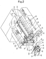
- Fig. 2 is a perspective view of a conveyance path from an insertion of a recording sheet to a discharge of the recording sheet in the plotter shown in Fig. 1.
- Fig. 3 is a perspective view of a printing section of the plotter shown in Fig. 1.
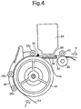
- Fig. 4 is a cross-sectional view of a first position control member and a second position control member showing in Fig. 2.
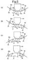
- Fig. 5(a) is a typical illustration showing a positional relation in the event that both the first and second position control members shown in Fig. 4 press on the upside of a recording sheet
- Fig. 5(b) is a typical illustration showing a positional relation in the event that the first position control member presses on the upside of the recording sheet, while the second position control member presses on the underside of the recording sheet
- Fig. 5(c) is a typical illustration showing a positional relation in the event that the first position control member presses on the underside of the recording sheet, while the second position control member presses on the upside of the recording sheet
- Fig. 5(d) is a typical illustration showing a positional relation in the event that both the first and second position control members press on the underside of the recording sheet.
- Fig. 6 is a cross-sectional view of a first position control member and a second position control member with which a plotter according to a second embodiment of an image forming apparatus employing an ink-jet system of the present invention is provided.
- Fig. 7 is a grossly enlarged sectional view of the vicinity of the first position control member and the second position control member shown in Fig. 6.
- Fig. 8 is a perspective view of a path from an insertion of a recording sheet to a discharge of the recording sheet in a plotter according to a third embodiment of an image forming apparatus employing an ink-jet system of the present invention, the plotter being shown on an open basis for the purpose of better understanding.
- Fig. 9 is a perspective view of the plotter shown in Fig. 8 but cutting off a carriage.
- Fig. 10 is a perspective view of a configuration of parts facing a recording sheet, of a recording medium flotation prevention member shown in Fig. 9.
- a plotter 10 according to the first embodiment shown in Fig. 1 is fixed on the top of a stand 12 equipped with casters 12a.
- the plotter 10 has an operation unit 14 for operating the plotter 10. Operating various types of switches and the like provided on the operation unit 14 permits instructions for a sheet size, on-line/off-line, a command, etc.
- a recording sheet, which is inserted into a recording sheet insertion inlet 16 from an arrow A direction, is conveyed into the inside of the plotter 10 in accordance with an instruction issued from the operation unit 14, and is discharged after printing for an image.
- the plotter 10 has also a cover 18 for covering the inside of the plotter 10.
- the plotter 10 may perform a printing selectively either on a recording sheet inserted from the recording sheet insertion inlet 16 and a recording sheet (a rolled sheet 20) wound as a roll.
- a conveyance path for recording sheets inserted from the recording sheet insertion inlet 16 a conveyance path for recording sheets inserted from the recording sheet insertion inlet 16.
- a recording sheet (for example, a large-sized cut sheet) is regularly placed on a cover 22 for the rolled sheet 20 and is inserted into the recording sheet insertion inlet 16 from an arrow A direction.
- the recording sheet inserted passes between the cover 22 and an upper guide 24, and reaches the upper portion (an example of an image forming area referred to in the present invention) of a print board 36 via a first position control member 34, while being supported by sheet conveyance rollers 28a and 28b mounted on a lower conveyance roller supporting plate 26 and a sheet conveyance roller 28c mounted on an upper conveyance roller supporting plate 30, and a driving roller 32 (the sheet conveyance roller 28c and the driving roller 32 are an example of a first conveyance member referred to in the present invention).
- the recording sheet which has passed through a second position control member 38 formed on a portion, located at the downward stream end with respect to the recording sheet conveyance direction, of the print board 36, is discharged while being supported by a discharge roller 40 and spurs 42 (the discharge roller 40 and the spurs 42 are an example of a second conveyance member referred to in the present invention).
- the discharge roller 40 and the spurs 42 are an example of a second conveyance member referred to in the present invention.
- part located at the upper portion of the print board 36 is, as will be described later, controlled by the first position control member 34 and the second position control member 38 so that flatness of the recording sheet is maintained.
- the plotter 10 has gears 44, 45, 46 and 47 and a motor 48 for rotating the driving roller 32 and the discharge roller 40.
- the print unit has a carriage 50 which reciprocates in an arrow B direction (an example of a predetermined direction referred to in the present invention).
- the carriage 50 has a head holder 52 on which print heads 54 accommodating color inks (for example, cyan, magenta, yellow and black of inks), respectively, are mounted.
- the carriage 50 is fixed on a belt 58 which is coupled with a driving source (not illustrated).
- the belt 58 reciprocates in an arrow B direction in accordance with a forward-backward rotation of the driving source. Reciprocation of the belt 58 in the arrow B direction causes the carriage 50 to reciprocate in the arrow B direction in accordance with a guide rail 60.
- a recording sheet is intermittently conveyed in a direction (recording sheet conveyance direction) perpendicular to the arrow B direction.
- the recording sheet is temporarily stopped, and while the carriage 50 reciprocates in the arrow B direction, ink is ejected from the ink ejection outlets in accordance with image information applied to the print heads 54 onto a portion, of the recording sheet, which portion is located at an image forming area formed in front of an ink ejection face 56 (cf. Fig. 4).
- the recording sheet is conveyed by a predetermined length so that a subsequent band of image is formed on a new portion of the recording sheet, which is located at the image forming area. This operation is repeated throughout the overall length of the recording sheet.
- a color image is formed on the recording sheet.
- the recording sheet on which the color image is formed is discharged along a discharge guide 62 while being supported by the discharge roller 40 and the spurs 42.
- the first position control member 34 and the second position control member 38 extend in the arrow B direction (direction perpendicular to the recording sheet conveyance direction).
- the first position control member 34 consists of a fine line-like shaped member and offers such a state that it is stretched. As shown in Fig. 2, one end 34a of the first position control member 34 is fixed to a right side plate 64 through a right position plate 66 which is fixed on the right side plate 64 in such a manner that the one end 34a is movable in the recording sheet conveyance direction.
- another end 34b of the first position control member 34 is connected to a spring 72 through a cut-out of a left position plate 70 which is fixed on the left side plate 68 in such a manner that the another end 34b is movable in the recording sheet conveyance direction.
- the first position control member 34 is fixed in the state that a given tension is applied thereto. In this manner, applying a given tension to the first position control member 34 ensures an exact linearity.
- the first position control member 34 expands due to changes in the temperature of environment, frictional heat and the like, the corresponding expansion may be absorbed by the spring 72.
- a position of the first position control member 34 is adjusted in such a manner that the right position plate 66 and the left position plate 70 are moved so that the first position control member 34 is parallel to the guide rail 60 (cf. Fig. 3).
- the second position control member 38 is formed on a portion, of the print board 36, located at the downward stream end with respect to the recording sheet conveyance direction, and extends in the arrow B direction and is parallel to the guide rail 60 and the first position control member 34.
- the guide rail 60, the first position control member 34 and the second position control member 38 are arranged to be parallel to one another.
- a recording sheet which is conveyed through supporting by the driving roller 32 and the sheet conveyance roller 28c, is controlled in its position through being pressed by the lower portion of the first position control member 34 and through being pressed by the upper portion of the second position control member 38.
- the recording sheet 74 is conveyed from an arrow C direction in such a manner that the recording sheet 74 is pressed by the sheet conveyance rollers 28a, 28b and 28c and is wound around the driving roller 32.
- the recording sheet 74 passed through the sheet conveyance roller 28c is conveyed while the upper surface of the recording sheet 74 is pressed by the first position control member 34 from the upper side.
- the recording sheet 74 passed through the image forming area is subjected to printing in the image forming area by the print heads 54 while the lower surface of the recording sheet 74 is pressed by the second position control member 38 from the lower side.
- the first position control member 34 a metallic single wire and fine lines in which wires are twisted may be used. In order to reduce a sliding sound due to sliding with a recording sheet, it is acceptable to use wires which are subjected to a coating treatments of resin such as Nylon and Teflon.
- the second position control member 38 is made of a mold material, a sheet metal, etc., since the linearity is required for the second position control member 38. It is noted that according to experiments, a metallic round bar is preferable.
- the recording sheet 74 is conveyed through supporting by the driving roller 32 and the sheet conveyance rollers 28a, 28b and 28c, while the upper surface of the recording sheet 74 is pressed by the first position control member 34 and the lower surface of the recording sheet 74 is pressed by the second position control member 38. Further, the recording sheet 74 is conveyed through supporting by the discharge roller 40 and the spur 42, and then discharged in an arrow D direction. Accordingly, of the recording sheet 74 on the way of conveyance, the portion 74a located at the image forming area in front of the ink ejection surface 56 (upside of the print board 36) is pulled by the first position control member 34 and the second position control member 38.
- the fine line-like shaped member is pulled through utilization of the side board of the main frame of the apparatus. This feature makes it possible to easily ensure the linearity of the fine line-like shaped member, and thus even in the event that the printing is performed on a large-sized recording sheet, it is possible to ensure flatness of the recording sheet. Further, in the event that a flexibility of fine line-like shaped member is used, an impact such as a fall and a vibration involves no changes in the mounting position, and thus it is possible to maintain the fine line-like shaped member with great accuracy.
- the first position control member 34 consists of the fine line-like shaped member, it does not occupy a great deal of space. This feature permits the first position control member 34 to approach the print heads 54. Consequently, it is possible to shorten a distance between the first position control member 34 and the second position control member 38, so that the surface of the recording sheet located at the image forming area offers a great accuracy of plane, and thereby obtaining a good image.
- the first position control member 34 and the second position control member 38 may be adjusted in their position upward and downward in accordance with the thickness of the recording sheet 74. This feature makes it possible to obtain a good image even if the thickness of the recording sheet 74 varies.
- Fig. 5(a) shows a positional relation in the event that both the first and second position control members 34 and 38 press on the upside (image surface) 74a of the recording sheet 74.
- Fig. 5(b) shows a positional relation in the event that the first position control member 34 presses on the upside 74a of the recording sheet 74, while the second position control member 38 presses on the underside (non-image surface) 74b of the recording sheet 74.
- Fig. 5(c) shows a positional relation in the event that the first position control member 34 presses on the underside 74b of the recording sheet 74, while the second position control member 38 presses on the upside 74a of the recording sheet 74.
- Fig. 5(d) shows a positional relation in the event that both the first and second position control members 34 and 38 press on the underside 74b of the recording sheet 74.
- FIG. 6 An appearance of the plotter according to the second embodiment is the same as the plotter shown in Fig. 1, and also with respect to structural elements they are the similar to those of Fig. 1. Consequently, in Figs. 6 and 7, the same parts are denoted by the same reference numbers as those of Figs. 1 to 5.
- An aspect of the plotter according to the second embodiment resides in the point that a horizontality ensuring member 80 is fixed on the print board 36 and a second position control member 82 is fixed on the horizontality ensuring member 80.
- the structure of the first position control member 34 shown in Figs. 6 and 7 is the same as that of the first position control member 34 shown in Figs. 2 and 4, and thus its explanation will be omitted.
- the horizontality ensuring member 80 is detachably fixed on a portion of the print board 36, which portion is located at the downward stream end with respect to the recording sheet conveyance direction.
- the horizontality ensuring member 80 adjusts a position of the second position control member 82 so that a portion of the recording sheet 74, which portion is located at the image forming area, is kept parallel to the ink ejection surface 56.
- the second position control member 82 is detachably fixed on the portion of the print board 36, which portion is located at the downward stream end with respect to the recording sheet conveyance direction, through the horizontality ensuring member 80.
- the second position control member 82 is a section "D"-like configuration of fine line-like shaped member extending in an arrow B direction (the vertical direction with respect to the sheet faces of Figs. 6 and 7, cf. Fig. 2), and is in contact with the horizontality ensuring member 80 on its flat face.
- This feature makes it possible to ensure a smooth conveyance for the recording sheet 74 and the linearity of the second position control member 82.
- the second position control member 82 is also made of a mold material, a sheet metal, etc., since the linearity is required also for the second position control member 82. It is noted that according to experiments, a round bar made of steel, in 5mm in diameter is preferable.
- the first position control member 34 and the second position control member 82 are arranged to be parallel to one another.
- a recording sheet which is conveyed through supporting by the driving roller 32 and the sheet conveyance roller 28c, is controlled in its position through being pressed by a curved surface 34a of the first position control member 34 and through being pressed by the curved surface 82a of the second position control member 82.
- the interval between the face of the recording sheet located at the image forming area and the print heads 54 is 1 to 2 mm, and the interval between the recording sheet and the print board 36 is at least 2 to 5 mm.
- the first position control member 34 and the second position control member 82 may be adjusted vertically in their position in accordance with thickness of the recording sheet 74, so that a good image can be obtained even if thickness of the recording sheet 74 is varied.
- FIG. 8 An appearance of the plotter according to the third embodiment is the same as the plotter shown in Fig. 1, and also with respect to structural elements they are the similar to those of Fig. 1. Consequently, in Figs. 8 to 10, the same parts are denoted by the same reference numbers as those of Figs. 1 to 5.
- a plotter 100 may perform a printing selectively either on a sheet-like shaped recording sheet (a cut sheet) inserted from the recording sheet insertion inlet 16 and a recording sheet (a rolled sheet) 20 wound as a roll.
- a conveyance path for cut sheets inserted from the recording sheet insertion inlet 16 may be described.
- a large-sized cut sheet is regularly placed on the cover 22 for the rolled sheet 20 and is inserted into the recording sheet insertion inlet 16 from an arrow A direction.
- the cut sheet inserted passes between the cover 22 and an upper guide 24, and reaches the upper portion (an example of an image forming area referred to in the present invention) 37 of the print board 36, while being supported by both the sheet conveyance roller 28a rotatably fixed on th lower conveyance roller supporting plate 26 and the sheet conveyance roller 28c rotatably fixed on the upper conveyance roller supporting plate 30, and the driving roller 32.
- the cut sheet, which has passed through the upper side of the print board 36 is discharged while being supported by the discharge roller 40 and the spurs 42 which is located at the upper side of the discharge roller 40.
- the spurs 42 are rotatably fixed on a spur plate 43.
- the plotter 100 has the carriage 50 which reciprocates in an arrow B direction.
- the carriage 50 has a head holder 52 on which four print heads 54 accommodating four types of color inks (for example, cyan, magenta, yellow and black of inks), respectively, are mounted.
- the carriage 50 is fixed on a belt 58 which is coupled with a driving motor (not illustrated).
- the belt 58 reciprocates in an arrow B direction in accordance with a forward-backward rotation of the driving motor. Reciprocation of the belt 58 in the arrow B direction causes the carriage 50 to reciprocate in the arrow B direction in accordance with the guide rail 60.
- a cut sheet is intermittently conveyed in a direction (an example of the recording sheet conveyance direction referred to in the present invention) perpendicular to the arrow B direction.
- the cut sheet is temporarily stopped, and while the carriage 50 reciprocates in the arrow B direction, ink is ejected from the print heads 54 in accordance with image information applied to the print heads 54 to form an a band of image on a portion, of the cut sheet, which portion is located at the image forming area 37.
- the cut sheet is conveyed by a predetermined length so that a subsequent band of image is formed on the image forming area 37. This operation is repeated throughout the overall length of the cut sheet.
- a color image is formed on the cut sheet.
- the cut sheet on which the color image is formed is discharged along the discharge guide 62 while being supported by the discharge roller 40 and the spurs 42.
- the carriage 50 comprises the head holder 52 for detachably holding four print heads 54, a bearing 102 and a slider 104 for reciprocating the carriage 50 in the arrow B direction, and an electric equipment unit 106 for controlling the print heads 54 in accordance with image information.
- the bearing 102 is of the shape of a horseshoe, and is disposed downward of the electric equipment unit 106.
- the guide rail 60 is fitted into the bearing 102 so that the carriage 50 is guided by the guide rail 60.
- the slider 104 is in contact with a sub-rail 108 (in Fig. 8 it is omitted).
- a linear sensor (not illustrated), which is mounted on the under portion of the carriage 50, reads the scale of a linear scale 110.
- the carriage 50 may reciprocate while exactly detecting its position.
- the electric equipment unit 106 is disposed near the print heads 54 so as to be hard affected by noises, and loads thereon various types of electronic parts.
- a recording medium floating prevention member 114 is disposed for each print head 54 in the more upward stream with respect to the recording sheet conveyance direction than the ink ejection outlet of the associated print head 54 and in the vicinity of the ink ejection outlet.
- the recording medium floating prevention member 114 is fixed on the carriage 50, and is closer to the recording sheet 74 as compared with the print head 54. There is ensured a gap between the recording medium floating prevention member 114 and the recording sheet 74.
- the recording medium floating prevention member 114 is made of polyoxymethylene or fluororesin, and is tough and low in coefficient of friction to recording sheets. Consequently, as will be described later, even if a convex portion of the recording sheet 74 is in contact with the recording medium floating prevention member 114, there occurs no frictional force that is an obstacle to an image formation and a conveyance of the recording sheet 74.
- each of ends 114a in the arrow B direction is rounded and smoothed.
- each of ends 114b in the arrow C direction is also rounded and smoothed.
- the portions facing the recording sheet 74 are smoothly formed. Consequently, even if an edge of the recording sheet 74 in the width direction of the recording sheet 74 is curled up, it does not happen, when the carriage 50 reciprocates in the arrow B direction, that the curled up portion of the recording sheet 74 catches the recording medium flotation prevention member 114 and as a result the recording sheet 74 is broken.
- the recording medium flotation prevention member 114 is formed for each print head 54. It is acceptable, however, that a single recording medium flotation prevention member, which extends in the arrow B direction, is formed on the carriage 50 in a straight line. Further, according to the present embodiment, the recording medium flotation prevention member 114 is formed on the carriage 50. It is acceptable, however, that the recording medium flotation prevention member is formed on the print heads 54. This arrangement makes it easy to form the recording medium flotation prevention member at a place nearer to the ink ejection outlets. Further, in this case, even if an arrangement of a plurality of print heads 54 is somewhat out of line, it is possible to readily arrange the recording medium flotation prevention member in accordance with the arrangement of the print heads 54.
- the first image forming apparatus employing an ink-jet system of the present invention
- a portion located at the image forming area is stretched, and an interval between this portion and the ink ejection surface is kept at a predetermined interval.
- ink ejected from the ink ejection outlets is absorbed into the recording sheet, so that a fiber of the recording sheet expands, no unevenness is formed on the recording sheet. Therefore, it is possible to suppress the cocking.
- a surface of the recording sheet located at the image forming area assumes a plane through being stretched by the first position control member and the second position control member. This feature makes it possible, even if a large-sized recording sheet is used, to maintain the interval between the surface of the recording sheet located at the image forming area and the ink ejection surface constant, and thus it is possible to expect a good printing.
- both the first position control member and the second position control member extend in a predetermined direction in which the ink ejection surface reciprocates, it means that the recording sheet is pressed in the width direction of the recording sheet.
- At least one of the first position control member and the second position control member is a fine line-like shaped one spread in a predetermined direction, it does not occupy a great deal of space, and thus it is permitted to place the position control member approaching the ink ejection surface.
- This makes it possible to shorten an interval between the first position control member and the second position control member and whereby the surface of the recording sheet located at the image forming area assumes a greater precision of plane. Thus, it is possible to obtain a good image.
- a position in which the first conveyance member supports the recording sheet is located at a position which is higher than the first position control member, and a position in which the second conveyance member supports the recording sheet is located at a position which is lower than the second position control member or the same height as the second position control member.
- the second position control member in the event that the first position control member presses, of both the surfaces of the recording sheet, a surface facing the ink ejection surface, and the second position control member presses, of both the surfaces of the recording sheet, a surface opposite to the surface facing the ink ejection surface, the second position control member is not in contact with a surface of the recording sheet on which an image has been formed. This feature makes it possible to prevent a turbulence of images due to the contact of the second position control member with the surface of the recording sheet.
- positions in which the first conveyance member and the second conveyance member support the recording sheet, respectively are located at positions which are lower than the first position control member and the second position control member, respectively. This feature makes it easy to ensure flatness of the surface of the recording sheet located at the image forming area.
- the second position control member is not in contact with a surface of the recording sheet on which an image has been formed. This feature makes it possible to prevent a turbulence of images due to the contact of the second position control member with the surface of the recording sheet.
- At least one of the first position control member and the second position control member is a fine line-like shaped one
- the fourth image forming apparatus employing an ink-jet system of the present invention
- a portion located at the image forming area is stretched, and an interval between this portion and the ink ejection surface is kept at a predetermined interval.
- ink ejected from the ink ejection outlets is absorbed into the recording sheet, so that a fiber of the recording sheet expands, no unevenness is formed on the recording sheet. Therefore, it is possible to suppress the cocking.
- a surface of the recording sheet located at the image forming area assumes a plane through being stretched by the first position control member and the second position control member.
- This feature makes it possible, even if a large-sized recording sheet is used, to maintain the interval between the surface of the recording sheet located at the image forming area and the ink ejection surface constant, and thus it is possible to expect a good printing. Further, the use of the horizontality ensuring member detachably fixed on the second position control member makes it possible to adjust a position of the second position control member so that a portion of the recording sheet, which portion is located at the image forming area, is kept parallel to the ink ejection surface.
- the use of the horizontality ensuring member makes it possible that the portion of the recording sheet, which portion is located at the image forming area, is kept parallel to the ink ejection surface.
- each of the first position control member and the second position control member has a curved surface pressing the recording sheet, it is possible to ensure a smooth conveyance for the recording sheet.
- the convex portion is pressed, and thus the convex portion is not in contact with the print head.
- This feature makes it possible to prevent the print head from being damages and to prevent sheet powders from adhering to the ink ejection outlets, and thereby improving the image quality since ink is ejected normally.
- the recording medium floating prevention member is made of polyoxymethylene or fluororesin, it is low in coefficient of friction to recording sheets. Consequently, even if a convex portion of the recording sheet is in contact with the recording medium floating prevention member, there occurs no frictional force that is an obstacle to an image formation and a conveyance of the recording sheet.
- the recording medium floating prevention member is formed on the print head, it is more easy to form the recording medium floating prevention member nearer the ink ejection outlets.
- the recording medium floating prevention member even if an arrangement of a plurality of print heads is somewhat out of line, it is possible to readily arrange the recording medium floating prevention member in accordance with the arrangement.
- the recording medium floating prevention member is formed on the carriage, there is no need to form the recording medium floating prevention member for each print head, and thereby reducing the cost.
Landscapes
- Ink Jet (AREA)
Priority Applications (1)
| Application Number | Priority Date | Filing Date | Title |
|---|---|---|---|
| EP02006740A EP1221378A3 (de) | 1996-01-22 | 1997-01-21 | Vorrichtung zur Tintenstrahlbilderzeugung |
Applications Claiming Priority (13)
| Application Number | Priority Date | Filing Date | Title |
|---|---|---|---|
| JP2625596A JPH09193374A (ja) | 1996-01-22 | 1996-01-22 | 画像形成装置 |
| JP26255/96 | 1996-01-22 | ||
| JP2625596 | 1996-01-22 | ||
| JP4571196A JP3319932B2 (ja) | 1996-03-04 | 1996-03-04 | インクジェット方式画像形成装置 |
| JP45711/96 | 1996-03-04 | ||
| JP4571196 | 1996-03-04 | ||
| JP47834/96 | 1996-03-05 | ||
| JP4783496 | 1996-03-05 | ||
| JP4783496A JP3278344B2 (ja) | 1996-03-05 | 1996-03-05 | インクジェット方式画像形成装置 |
| JP13905696 | 1996-05-31 | ||
| JP13905696A JP3365905B2 (ja) | 1996-05-31 | 1996-05-31 | インクジェット方式画像形成装置 |
| JP139056/96 | 1996-05-31 | ||
| PCT/JP1997/000114 WO1997027055A1 (fr) | 1996-01-22 | 1997-01-21 | Dispositif de formation d'images a jet d'encre |
Related Child Applications (1)
| Application Number | Title | Priority Date | Filing Date |
|---|---|---|---|
| EP02006740A Division EP1221378A3 (de) | 1996-01-22 | 1997-01-21 | Vorrichtung zur Tintenstrahlbilderzeugung |
Publications (3)
| Publication Number | Publication Date |
|---|---|
| EP0876913A1 true EP0876913A1 (de) | 1998-11-11 |
| EP0876913A4 EP0876913A4 (de) | 1999-03-17 |
| EP0876913B1 EP0876913B1 (de) | 2003-06-25 |
Family
ID=27458459
Family Applications (2)
| Application Number | Title | Priority Date | Filing Date |
|---|---|---|---|
| EP02006740A Withdrawn EP1221378A3 (de) | 1996-01-22 | 1997-01-21 | Vorrichtung zur Tintenstrahlbilderzeugung |
| EP97900468A Expired - Lifetime EP0876913B1 (de) | 1996-01-22 | 1997-01-21 | Tintenstrahllaufzeichnungsvorrichtung |
Family Applications Before (1)
| Application Number | Title | Priority Date | Filing Date |
|---|---|---|---|
| EP02006740A Withdrawn EP1221378A3 (de) | 1996-01-22 | 1997-01-21 | Vorrichtung zur Tintenstrahlbilderzeugung |
Country Status (4)
| Country | Link |
|---|---|
| US (1) | US6161973A (de) |
| EP (2) | EP1221378A3 (de) |
| DE (1) | DE69723054T2 (de) |
| WO (1) | WO1997027055A1 (de) |
Families Citing this family (3)
| Publication number | Priority date | Publication date | Assignee | Title |
|---|---|---|---|---|
| US7971989B2 (en) * | 2005-12-07 | 2011-07-05 | Seiko Epson Corporation | Printer used with rolled sheet |
| US8052272B2 (en) * | 2009-02-22 | 2011-11-08 | Hewlett-Packard Development Company, L.P. | Fluid-ejection device having rollers |
| US8358323B2 (en) * | 2009-08-17 | 2013-01-22 | Xerox Corporation | Write heating architecture for dual mode imaging systems |
Citations (9)
| Publication number | Priority date | Publication date | Assignee | Title |
|---|---|---|---|---|
| JPS6021276A (ja) * | 1983-07-15 | 1985-02-02 | Ricoh Co Ltd | インクジエツト記録装置 |
| JPS61280967A (ja) * | 1985-06-07 | 1986-12-11 | Canon Inc | インクジエツト記録装置 |
| EP0472218A2 (de) * | 1990-08-24 | 1992-02-26 | Canon Kabushiki Kaisha | Aufzeichnungsgerät |
| JPH04219244A (ja) * | 1990-09-18 | 1992-08-10 | Canon Inc | インクジェットプリンタ |
| US5156466A (en) * | 1989-10-18 | 1992-10-20 | Fujitsu Limited | Method and apparatus for adjusting the spacing between head and platen in an impact printer or the like |
| JPH04366639A (ja) * | 1991-06-13 | 1992-12-18 | Seiko Epson Corp | インクジェットプリンタの印字機構 |
| JPH079713A (ja) * | 1993-06-03 | 1995-01-13 | Hewlett Packard Co <Hp> | プリンタ |
| JPH0717036A (ja) * | 1993-07-01 | 1995-01-20 | Canon Inc | インクジェット記録装置 |
| GB2290262A (en) * | 1994-02-10 | 1995-12-20 | Seiko Epson Corp | Paper handling in ink jet printer. |
Family Cites Families (7)
| Publication number | Priority date | Publication date | Assignee | Title |
|---|---|---|---|---|
| JPS58179673A (ja) * | 1982-03-12 | 1983-10-20 | Hitachi Ltd | 用紙案内機構 |
| JPS60214983A (ja) * | 1984-02-29 | 1985-10-28 | Toshiba Corp | 画像形成装置 |
| US5065169A (en) * | 1988-03-21 | 1991-11-12 | Hewlett-Packard Company | Device to assure paper flatness and pen-to-paper spacing during printing |
| DE69025124T2 (de) * | 1989-10-19 | 1996-07-04 | Seiko Epson Corp | Tintenstrahldrucker |
| US5455604A (en) * | 1991-04-29 | 1995-10-03 | Tektronix, Inc. | Ink jet printer architecture and method |
| JP2959259B2 (ja) * | 1991-05-27 | 1999-10-06 | セイコーエプソン株式会社 | 印字装置 |
| JPH0761078A (ja) * | 1993-08-25 | 1995-03-07 | Canon Inc | インクジェットプリンタ |
-
1997
- 1997-01-21 EP EP02006740A patent/EP1221378A3/de not_active Withdrawn
- 1997-01-21 WO PCT/JP1997/000114 patent/WO1997027055A1/ja active IP Right Grant
- 1997-01-21 EP EP97900468A patent/EP0876913B1/de not_active Expired - Lifetime
- 1997-01-21 DE DE69723054T patent/DE69723054T2/de not_active Expired - Lifetime
- 1997-01-21 US US09/101,415 patent/US6161973A/en not_active Expired - Fee Related
Patent Citations (9)
| Publication number | Priority date | Publication date | Assignee | Title |
|---|---|---|---|---|
| JPS6021276A (ja) * | 1983-07-15 | 1985-02-02 | Ricoh Co Ltd | インクジエツト記録装置 |
| JPS61280967A (ja) * | 1985-06-07 | 1986-12-11 | Canon Inc | インクジエツト記録装置 |
| US5156466A (en) * | 1989-10-18 | 1992-10-20 | Fujitsu Limited | Method and apparatus for adjusting the spacing between head and platen in an impact printer or the like |
| EP0472218A2 (de) * | 1990-08-24 | 1992-02-26 | Canon Kabushiki Kaisha | Aufzeichnungsgerät |
| JPH04219244A (ja) * | 1990-09-18 | 1992-08-10 | Canon Inc | インクジェットプリンタ |
| JPH04366639A (ja) * | 1991-06-13 | 1992-12-18 | Seiko Epson Corp | インクジェットプリンタの印字機構 |
| JPH079713A (ja) * | 1993-06-03 | 1995-01-13 | Hewlett Packard Co <Hp> | プリンタ |
| JPH0717036A (ja) * | 1993-07-01 | 1995-01-20 | Canon Inc | インクジェット記録装置 |
| GB2290262A (en) * | 1994-02-10 | 1995-12-20 | Seiko Epson Corp | Paper handling in ink jet printer. |
Non-Patent Citations (6)
| Title |
|---|
| PATENT ABSTRACTS OF JAPAN vol. 009, no. 142 (M-388), 18 June 1985 & JP 60 021276 A (RICOH KK), 2 February 1985 * |
| PATENT ABSTRACTS OF JAPAN vol. 011, no. 146 (M-587), 13 May 1987 & JP 61 280967 A (CANON INC), 11 December 1986 * |
| PATENT ABSTRACTS OF JAPAN vol. 016, no. 569 (M-1343), 9 December 1992 & JP 04 219244 A (CANON INC), 10 August 1992 * |
| PATENT ABSTRACTS OF JAPAN vol. 017, no. 244 (M-1410), 17 May 1993 & JP 04 366639 A (SEIKO EPSON CORP), 18 December 1992 * |
| PATENT ABSTRACTS OF JAPAN vol. 095, no. 004, 31 May 1995 & JP 07 017036 A (CANON INC), 20 January 1995 * |
| See also references of WO9727055A1 * |
Also Published As
| Publication number | Publication date |
|---|---|
| EP0876913A4 (de) | 1999-03-17 |
| WO1997027055A1 (fr) | 1997-07-31 |
| EP1221378A2 (de) | 2002-07-10 |
| DE69723054T2 (de) | 2003-12-24 |
| DE69723054D1 (de) | 2003-07-31 |
| EP0876913B1 (de) | 2003-06-25 |
| US6161973A (en) | 2000-12-19 |
| EP1221378A3 (de) | 2002-08-21 |
Similar Documents
| Publication | Publication Date | Title |
|---|---|---|
| CN107264077B (zh) | 液体喷出装置及介质按压方法 | |
| KR100196314B1 (ko) | 잉크 제트 기록 장치 | |
| US6789889B2 (en) | Inkjet printing media handling system with advancing guide shim | |
| JP2006192814A (ja) | インクジェット記録装置 | |
| US9592685B2 (en) | Scanning inkjet printing system | |
| US6089773A (en) | Print media feed system for an ink jet printer | |
| JP3860651B2 (ja) | プリンタ機構 | |
| JPS63230380A (ja) | 肉厚印字媒体に対する印字ヘッドの間隔調整装置 | |
| US6161973A (en) | Ink-jet image forming device | |
| JP2000006387A (ja) | インクジェットプリンタ | |
| US6742948B2 (en) | Apparatus for flattening a substrate and method thereof | |
| JP3809765B2 (ja) | 記録装置 | |
| JP2002264419A (ja) | インクジェット記録装置および該インクジェット記録装置における被記録媒体とインクジェット記録ヘッドとの間隔を調整する方法 | |
| US20170239960A1 (en) | Recording apparatus | |
| US20080130066A1 (en) | Carriage moving device | |
| US6394672B1 (en) | Imaging apparatus having a biased platen | |
| US7771134B2 (en) | Image recording apparatus including cutting unit and guide member with friction member | |
| JPH0230575A (ja) | 記録装置 | |
| JPH0789069A (ja) | インクジェットプリンタ | |
| JPH1158706A (ja) | インクジェット方式画像形成装置 | |
| JP3278344B2 (ja) | インクジェット方式画像形成装置 | |
| US6371611B1 (en) | Media feed unit for an ink jet printer | |
| JP3365905B2 (ja) | インクジェット方式画像形成装置 | |
| JP3581606B2 (ja) | 記録装置 | |
| JP3319932B2 (ja) | インクジェット方式画像形成装置 |
Legal Events
| Date | Code | Title | Description |
|---|---|---|---|
| PUAI | Public reference made under article 153(3) epc to a published international application that has entered the european phase |
Free format text: ORIGINAL CODE: 0009012 |
|
| 17P | Request for examination filed |
Effective date: 19980724 |
|
| AK | Designated contracting states |
Kind code of ref document: A1 Designated state(s): DE FR GB |
|
| A4 | Supplementary search report drawn up and despatched |
Effective date: 19990203 |
|
| AK | Designated contracting states |
Kind code of ref document: A4 Designated state(s): DE FR GB |
|
| 17Q | First examination report despatched |
Effective date: 20011210 |
|
| GRAH | Despatch of communication of intention to grant a patent |
Free format text: ORIGINAL CODE: EPIDOS IGRA |
|
| GRAH | Despatch of communication of intention to grant a patent |
Free format text: ORIGINAL CODE: EPIDOS IGRA |
|
| GRAH | Despatch of communication of intention to grant a patent |
Free format text: ORIGINAL CODE: EPIDOS IGRA |
|
| GRAA | (expected) grant |
Free format text: ORIGINAL CODE: 0009210 |
|
| RIN1 | Information on inventor provided before grant (corrected) |
Inventor name: SASAME, SATORU Inventor name: KIYOHARA, NAOKI Inventor name: IZUMA, KENSUKE Inventor name: SUZUKI, RYOMA Inventor name: NISIMURA, KAZUHIRO Inventor name: MURAKAMI, KAZUHIRO Inventor name: NAMEKATA, KIYOKAZU Inventor name: KAWAMURA, IWAO |
|
| AK | Designated contracting states |
Designated state(s): DE FR GB |
|
| REG | Reference to a national code |
Ref country code: GB Ref legal event code: FG4D |
|
| REF | Corresponds to: |
Ref document number: 69723054 Country of ref document: DE Date of ref document: 20030731 Kind code of ref document: P |
|
| RAP2 | Party data changed (patent owner data changed or rights of a patent transferred) |
Owner name: CANON FINETECH INC. |
|
| ET | Fr: translation filed | ||
| PLBE | No opposition filed within time limit |
Free format text: ORIGINAL CODE: 0009261 |
|
| STAA | Information on the status of an ep patent application or granted ep patent |
Free format text: STATUS: NO OPPOSITION FILED WITHIN TIME LIMIT |
|
| 26N | No opposition filed |
Effective date: 20040326 |
|
| REG | Reference to a national code |
Ref country code: FR Ref legal event code: TP Ref country code: FR Ref legal event code: CD |
|
| REG | Reference to a national code |
Ref country code: FR Ref legal event code: PLFP Year of fee payment: 20 |
|
| PGFP | Annual fee paid to national office [announced via postgrant information from national office to epo] |
Ref country code: FR Payment date: 20151208 Year of fee payment: 20 |
|
| PGFP | Annual fee paid to national office [announced via postgrant information from national office to epo] |
Ref country code: DE Payment date: 20160112 Year of fee payment: 20 |
|
| PGFP | Annual fee paid to national office [announced via postgrant information from national office to epo] |
Ref country code: GB Payment date: 20160120 Year of fee payment: 20 |
|
| REG | Reference to a national code |
Ref country code: DE Ref legal event code: R071 Ref document number: 69723054 Country of ref document: DE |
|
| REG | Reference to a national code |
Ref country code: GB Ref legal event code: PE20 Expiry date: 20170120 |
|
| PG25 | Lapsed in a contracting state [announced via postgrant information from national office to epo] |
Ref country code: GB Free format text: LAPSE BECAUSE OF EXPIRATION OF PROTECTION Effective date: 20170120 |