EP0876570B1 - Surface de bruleur - Google Patents
Surface de bruleur Download PDFInfo
- Publication number
- EP0876570B1 EP0876570B1 EP97900010A EP97900010A EP0876570B1 EP 0876570 B1 EP0876570 B1 EP 0876570B1 EP 97900010 A EP97900010 A EP 97900010A EP 97900010 A EP97900010 A EP 97900010A EP 0876570 B1 EP0876570 B1 EP 0876570B1
- Authority
- EP
- European Patent Office
- Prior art keywords
- burner
- flame
- process according
- bores
- burner pipe
- Prior art date
- Legal status (The legal status is an assumption and is not a legal conclusion. Google has not performed a legal analysis and makes no representation as to the accuracy of the status listed.)
- Expired - Lifetime
Links
Images

Classifications
-
- F—MECHANICAL ENGINEERING; LIGHTING; HEATING; WEAPONS; BLASTING
- F23—COMBUSTION APPARATUS; COMBUSTION PROCESSES
- F23D—BURNERS
- F23D14/00—Burners for combustion of a gas, e.g. of a gas stored under pressure as a liquid
- F23D14/46—Details, e.g. noise reduction means
- F23D14/60—Devices for simultaneous control of gas and combustion air
-
- F—MECHANICAL ENGINEERING; LIGHTING; HEATING; WEAPONS; BLASTING
- F23—COMBUSTION APPARATUS; COMBUSTION PROCESSES
- F23D—BURNERS
- F23D14/00—Burners for combustion of a gas, e.g. of a gas stored under pressure as a liquid
- F23D14/46—Details, e.g. noise reduction means
- F23D14/48—Nozzles
- F23D14/58—Nozzles characterised by the shape or arrangement of the outlet or outlets from the nozzle, e.g. of annular configuration
Definitions
- the present invention relates to a procedure to reduce nitrogen oxides when burning gaseous or gaseous fuels a burner to carry out the process.
- Firing systems for gaseous fuels or gas / liquid fuel mixtures are criteria such as economy, such as optimal efficiency and especially reduction the emissions of pollutants, such as nitrogen oxides, carbon monoxide and unburned hydrocarbons basically too fulfilling demands.
- US 3 061 001 describes a burner for gaseous Fuels arranged in the burner surface Flame holes, with at least a part of the holes in Shape of equilateral triangles is arranged.
- the task in of said US patent is that To prevent the flames from kicking back into the holes which is achieved on the one hand by the bores are largely filled with fuel mixture and on the other hand, by the burner surface by appropriate constructive measures is cooled. A reducing the Pollutants in the exhaust gases are not under discussion.
- a burner surface is proposed in US Pat. No. 3,936,003. in which the individual flame holes are so apart spaced that between the flames Exhaust gases or flue gases are sucked in by the flame root become.
- WO95 / 23315 also proposes the flame bores to be arranged in such a way that between the Flame exhaust gases or flue gases are sucked back to the flame roots become.
- special Conditions assumed by the ones proposed therein Process especially for highly reactive combustion gases suitable, such as for hydrogen / methane mixtures, containing more than 90% hydrogen.
- fuel mixtures are usually burned of conventional fuels in combustion plants.
- the object is achieved by means of a Method according to the wording of claim 1 solved.
- the burner surface can be selected appropriately fundamentally determine the flame formation in all details. This applies in particular to the phenomena of flame stability, Carbon monoxide and nitrogen oxide emissions.
- a fluid jet such as a gas / air mixture it comes from an opening like a pipe or hole to form a free jet. This sucks surrounding medium and mixes with it as below with reference shown in Figure 1.
- parallel free jets each other and it comes depending on the characteristic sizes of the beam, to a changed Characteristics of the suction.
- the basic idea of the present invention is therefore Mixing exhaust gas into the fuel / air mixture from the environment, resulting in a drastic reduction in education of nitrogen oxides. This eliminates the need by means of pipes, control mechanisms and Exhaust gases from a combustion chamber and the fuel gas or gas mixture before this above the burner surface is burned.
- trained method is a burner tube operated longitudinally displaceable.
- a burner comprises a burner tube, which is slidably mounted in its longitudinal direction.
- reaction kinetic Effects such as flame stability, pollutant formation, etc. consider.
- a system is understood as optimization by suitable variation of operating parameters and Bring geometry into a desired state. Since the Operating parameters largely due to the requirements the geometry must be varied.
- this object is achieved by means of the special Further development of the method according to the wording according to claim 4 solved.
- a burner tube which is longitudinally displaceable in the axial direction and is arranged from a combustion chamber, it is proposed that terminate in or on the cylindrical burner tube Cylinder base, axially and concentrically from this protruding, another burner tube with a smaller diameter is arranged is on the surface of the hole pattern according to the invention is arranged.
- Further preferred design variants of the The inventive method are in the dependent claims 5-9 characterized.
- the proposed method according to the invention or the Suitable burners are suitable for carrying out the method especially for surface burners.
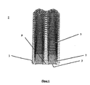
- Figure 1 shows schematically two parallel free jets 5, at which are, for example, two ignited fluid jets can act. These are generated by a gaseous Fuel through flame holes 3 on a burner surface 1 entered into a combustion chamber 2 for combustion become. In particular at the flame root 7 by the gas flowing into the combustion chamber 2 ambient gases into the The fuel-gas mixture is sucked in and mixed with it. So that the mixing of the exhaust gases from the environment according to the invention done in the best possible way, a Burner surface preferably shown according to a hole pattern in Fig. 2, formed.
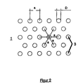
- Figure 2 shows a burner surface 1, comprising a plurality of flame holes or individual holes 3, which so are arranged so that each hole is direct to each of its Neighbor holes an identical, preferably corresponding an equilateral triangle, or approximately the same distance has.
- the distance between the holes is designated “a” in FIG. 2, the diameter of the holes with "D”.
- u speed of the flowing out of the hole
- ⁇ kinematic Viscosity of the medium.
- the present invention only uses the optimal design of the burner surface (hole arrangement) for exhaust gas circulation, as already mentioned at the beginning.
- the following equilateral triangles or similar patterns with the following parameters have proven to be advantageous for the optimal configuration of the hole pattern arrangement of the burner surface of a low-radiation surface burner: 1.5 ⁇ a / D ⁇ 6 [-] 3 ⁇ D ⁇ 10 [mm]
- Preferred parameter values are the values a / D of 2 up to 4 resp. from 2.2 to 3.5, while the value for Diameter D depends on the performance of the burner.
- a burner tube 4 is shown in section, comprising on the one hand a burner surface 1 with the inventive proposed hole pattern, as well as with an additional Arrangement for the design of a so-called base load level.
- the burner tube 4 designed according to the invention can be moved in the axial direction (arrow) on the Combustion chamber wall 21 into the combustion chamber or out of the combustion chamber 2 are moved.
- the power modulation range thus generated leads to a combustion chamber, which in extreme cases by one Order of magnitude is oversized. Especially in that Case where the burner tube is largely out of the combustion chamber 2 is withdrawn, this leads to a flame design, which is far from the optimum because the flame does not experience any stabilizing effects from the combustion chamber. For this reason, a so-called.
- Base load level suggested which of the flame is the one at their Stabilization provides the necessary "combustion chamber” and so the Enables combustion optimization.
- proposed combustion chamber of the flames in the small power range is arranged on the front of the burner tube 4 and with designated by the reference numeral 18.
- This combustion chamber 18 of the Base load level is formed by an additional one Another burner tube arranged on the front of the burner tube 4 24, on its burner surface 26 in turn flame bores or perforations 28 according to the proposed inventive Hole patterns are arranged.
- These holes 28 preferably have a smaller diameter D. than the diameter of the holes 3 in the surface 1 of the Burner tube 4.
- a lower axial limit 25 is proposed, which is advantageously made of a material which glows.
- the upper material is preferably made of the same material ring-shaped boundary 31 made which is ring-shaped axially around the further burner tube 24, the front Covering the surface of the cylinder bottom of the burner tube 4, is arranged.
- the power range is located on the burner tube 4 and is moved. So there is no relative movement of Burner and combustion chamber in the smallest output range.
- the Size of the base load level can vary from approx. 5-30% of the full load extend, preferably 5-10%.
- the formation of the burner surface the further burner tube 24 or the so-called.
- Base load level is done using the same as described above Pattern, which is also used for the main burner surface 1 becomes.
- the parameter selection of the pattern a / D, D can for base load and main burner surface are different.
- the upper and lower limits of the base load level advantageously consists of a glowable material, is achieved at all times, even if the Flame extinguished locally or transiently (typical phenomenon turbulent flames), the gas flowing past is heated and is ignited again. This enables approximately one of Carbon monoxide free operation, even with base load.
- the advantage of the design of a burner according to the invention 3 lies in ensuring the optimization flame formation in all power modulation areas and thereby maintaining extremely small emissions of Carbon monoxide and nitrogen oxides. This also makes it possible a burner with a proposed according to the invention To provide burner surface and with different Operate performance without being more optimal for ensuring Emission values the size of the combustion chamber is considerable or that optimal emission values even with oversized Combustion chambers are possible.
Landscapes
- Engineering & Computer Science (AREA)
- Chemical & Material Sciences (AREA)
- Combustion & Propulsion (AREA)
- Mechanical Engineering (AREA)
- General Engineering & Computer Science (AREA)
- Gas Burners (AREA)
- Transition And Organic Metals Composition Catalysts For Addition Polymerization (AREA)
- Adhesives Or Adhesive Processes (AREA)
- Combustion Of Fluid Fuel (AREA)
Claims (11)
- Procédé pour réduire les oxydes d'azote lors de la combustion d'un combustible ou mélange de combustibles gazeux ou gazeux/liquide au niveau d'un gicleur ou d'un brûleur tubulaire pourvu de perçages de flamme, étant précisé que les jets de fluide enflammés sont espacés les uns des autres de telle sorte qu'un agent environnant contenant des gaz de combustion ou des gaz brûlés est aspiré dans la zone de la base de la flamme afin de réduire la température de la flamme, et qu'une partie au moins des perçages de flamme sont disposés en forme de triangles équilatéraux, que le diamètre (D) des perçages de flamme est situé dans une plage de valeurs de 3-10 mm et que le rapport de l'écartement (a) desdits perçages sur leur diamètre (D), c'est-à-dire le rapport (a/D), est situé dans une plage de 2 à 4.
- Procédé selon la revendication 1, caractérisé en ce qu'on utilise un brûleur tubulaire sensiblement cylindrique avec des perçages de flamme disposés dans la paroi cylindrique.
- Procédé selon la revendication 1 ou 2, caractérisé en ce que le brûleur tubulaire est mobile longitudinalement dans le sens axial.
- Procédé selon la revendication 2 ou 3, caractérisé en ce que le brûleur tubulaire fonctionne comme brûleur principal et en ce que dans ou sur le fond de cylindre qui ferme le brûleur tubulaire cylindrique, on utilise un autre brûleur tubulaire concentrique qui part dudit fond et qui présente un diamètre plus petit, pour former ce qu'on appelle un étage de charge de base.
- Procédé selon l'une des revendications 2 à 4, caractérisé en ce que le rapport (a/D) des perçages de flamme disposés dans l'autre brûleur tubulaire ou étage de charge de base est situé dans la même plage de valeurs que le rapport (a/D) de la surface de brûleur principal ou du brûleur tubulaire.
- Procédé selon l'une des revendications 2 à 5, caractérisé en ce que le diamètre (D) des perçages prévus dans l'autre brûleur tubulaire ou étage de charge de base est plus petit que celui des perçages prévus dans la surface de brûleur principal.
- Procédé selon l'une des revendications 2 à 6, caractérisé en ce que l'autre brûleur tubulaire ou étage de charge de base a une forme cylindrique et comporte un fond de fermeture frontal ou une délimitation frontale qui dépasse radialement de la paroi cylindrique, avec un diamètre correspondant à peu près au diamètre du brûleur tubulaire ou du brûleur principal, et en ce qu'il est prévu sur la surface libre du fond de cylindre du brûleur principal ou du brûleur tubulaire une paroi annulaire qui couvre cette surface, le fond de fermeture et la paroi annulaire étant fabriqués de préférence à partir d'un matériau qui devient incandescent lors du fonctionnement du brûleur, comme par exemple de la tôle métallique, de la céramique, etc.
- Procédé selon Tune des revendications 1 à 7, caractérisé en ce que le mélange gaz combustible / air en grande partie pur qui traverse initialement le perçage de flamme est mélangé à partir de la zone de la base de la flamme avec un produit en grande partie exempt d'oxygène.
- Procédé selon l'une des revendications 1 à 8, caractérisé en ce que le brûleur tubulaire, pour commander la surface de brûleur active, est déplacé dans le sens axial pour entrer dans un espace de combustion ou de chauffe ou sortir de celui-ci, étant précisé qu'avec une charge de base, le brûleur tubulaire est sorti de l'espace de combustion ou de chauffe au maximum jusqu'au fond de fermeture du cylindre et que dans la zone de puissance ainsi minimale, la combustion des combustibles n'a lieu que grâce à l'autre brûleur tubulaire ou à l'étage de charge de base qui dépasse côté frontal.
- Brûleur pour la mise en oeuvre du procédé selon l'une des revendications 1 à 9, étant précisé qu'une partie au moins des perçages de flamme sont disposés en forme de triangles équilatéraux, que le rapport de l'écartement (a) desdits perçages sur leur diamètre (D), c'est-à-dire le rapport (a/D), a une valeur située dans une plage de 2 à 4, et que le diamètre (D) des perçages de flamme est situé dans une plage de valeurs de 3-10 mm.
- Brûleur selon la revendication 10, caractérisé en ce que le rapport (a/D) a une plage de valeurs de 2,2-3,5.
Applications Claiming Priority (4)
| Application Number | Priority Date | Filing Date | Title |
|---|---|---|---|
| CH203/96 | 1996-01-26 | ||
| CH20396 | 1996-01-26 | ||
| CH20396 | 1996-01-26 | ||
| PCT/CH1997/000004 WO1997027428A1 (fr) | 1996-01-26 | 1997-01-07 | Surface de bruleur |
Publications (2)
| Publication Number | Publication Date |
|---|---|
| EP0876570A1 EP0876570A1 (fr) | 1998-11-11 |
| EP0876570B1 true EP0876570B1 (fr) | 2002-07-03 |
Family
ID=4181608
Family Applications (1)
| Application Number | Title | Priority Date | Filing Date |
|---|---|---|---|
| EP97900010A Expired - Lifetime EP0876570B1 (fr) | 1996-01-26 | 1997-01-07 | Surface de bruleur |
Country Status (10)
| Country | Link |
|---|---|
| EP (1) | EP0876570B1 (fr) |
| JP (1) | JP2000503381A (fr) |
| AT (1) | ATE220189T1 (fr) |
| AU (1) | AU1137697A (fr) |
| CA (1) | CA2244103A1 (fr) |
| DE (1) | DE59707649D1 (fr) |
| DK (1) | DK0876570T3 (fr) |
| ES (1) | ES2180020T3 (fr) |
| NO (1) | NO315483B1 (fr) |
| WO (1) | WO1997027428A1 (fr) |
Families Citing this family (4)
| Publication number | Priority date | Publication date | Assignee | Title |
|---|---|---|---|---|
| US20120193452A1 (en) | 2009-12-11 | 2012-08-02 | Nv Bekaert Sa | Burner with low porosity burner deck |
| JP6088354B2 (ja) * | 2013-05-20 | 2017-03-01 | 公立大学法人首都大学東京 | ガス燃焼器の設計方法 |
| JP6331662B2 (ja) * | 2014-05-07 | 2018-05-30 | 三浦工業株式会社 | ガスバーナ |
| NL2020282B1 (nl) * | 2018-01-17 | 2019-07-25 | Atag Heating B V | Branderplaat voor een cv-ketel |
Family Cites Families (4)
| Publication number | Priority date | Publication date | Assignee | Title |
|---|---|---|---|---|
| US3061001A (en) * | 1958-09-12 | 1962-10-30 | Zink Co John | Gaseous fuel burner |
| US3936003A (en) * | 1973-12-03 | 1976-02-03 | Raytheon Company | Multiport high density burner |
| CH676743A5 (fr) * | 1985-04-11 | 1991-02-28 | Ygnis Sa | |
| NL9400280A (nl) * | 1994-02-23 | 1995-10-02 | Stichting Energie | Werkwijze voor de verbranding van hoogreaktieve gasvormige lucht/brandstof-mengsels en branderinrichting voor het uitvoeren van deze werkwijze. |
-
1997
- 1997-01-07 AT AT97900010T patent/ATE220189T1/de not_active IP Right Cessation
- 1997-01-07 DE DE59707649T patent/DE59707649D1/de not_active Expired - Fee Related
- 1997-01-07 AU AU11376/97A patent/AU1137697A/en not_active Abandoned
- 1997-01-07 EP EP97900010A patent/EP0876570B1/fr not_active Expired - Lifetime
- 1997-01-07 DK DK97900010T patent/DK0876570T3/da active
- 1997-01-07 WO PCT/CH1997/000004 patent/WO1997027428A1/fr active IP Right Grant
- 1997-01-07 JP JP9526383A patent/JP2000503381A/ja not_active Ceased
- 1997-01-07 ES ES97900010T patent/ES2180020T3/es not_active Expired - Lifetime
- 1997-01-07 CA CA002244103A patent/CA2244103A1/fr not_active Abandoned
-
1998
- 1998-07-21 NO NO19983361A patent/NO315483B1/no not_active IP Right Cessation
Also Published As
| Publication number | Publication date |
|---|---|
| NO315483B1 (no) | 2003-09-08 |
| CA2244103A1 (fr) | 1997-07-31 |
| NO983361L (no) | 1998-07-21 |
| JP2000503381A (ja) | 2000-03-21 |
| DE59707649D1 (de) | 2002-08-08 |
| DK0876570T3 (da) | 2002-11-04 |
| ES2180020T3 (es) | 2003-02-01 |
| NO983361D0 (no) | 1998-07-21 |
| WO1997027428A1 (fr) | 1997-07-31 |
| EP0876570A1 (fr) | 1998-11-11 |
| AU1137697A (en) | 1997-08-20 |
| ATE220189T1 (de) | 2002-07-15 |
Similar Documents
| Publication | Publication Date | Title |
|---|---|---|
| EP0834040B1 (fr) | Foyer avec un dispositif de brûleur et procédé de fonctionnement d'un foyer | |
| DE2408635C3 (de) | Verfahren zum Verbrennen von gasförmigem oder flüssigem Brennstoff | |
| EP0415008B1 (fr) | Procédé de combustion dans un brûleur à gaz | |
| DE60105913T2 (de) | WANDSTRAHLUNGSBRENNER MIT NIEDRIGER NOx-EMISSION | |
| DE4200073C2 (de) | Brenner für einen flüssigen oder gasförmigen Brennstoff mit geringem NO¶X¶-Ausstoß | |
| DE19923219B4 (de) | Bodenbrenner mit geringer NOx-Emission und Heizverfahren | |
| EP0095788A1 (fr) | Chambre de combustion d'une turbine à gaz et sa méthode | |
| CH680014A5 (fr) | ||
| DE4405894C2 (de) | Wasserrohrkessel | |
| DE69923797T2 (de) | Verfahren zum betrieb eines tangentialen feuerungssystems | |
| DE10257704A1 (de) | Verfahren zur Verbrennung eines Brennstoffs | |
| DE3930037A1 (de) | Wasserrohrkessel und verfahren zu dessen brennerbetrieb | |
| DE102005038662B4 (de) | Brennkopf und Verfahren zur Verbrennung von Brennstoff | |
| CH672366A5 (fr) | ||
| EP0876570B1 (fr) | Surface de bruleur | |
| DE2842125A1 (de) | Bodenfackel-vorrichtung | |
| DE2705647A1 (de) | Brenner fuer gasfoermigen oder fluessigen brennstoff | |
| WO1986006150A1 (fr) | Bruleur de combustibles gazeux, en particulier pour une chaudiere de chauffage, et procede de combustion de combustibles gazeux | |
| EP0602396B1 (fr) | Méthode de exploitation d'un générateur de chaleur | |
| EP2126471B1 (fr) | Flamme creuse | |
| WO2019224050A1 (fr) | Système de buses de carburant | |
| EP0683882B1 (fr) | Dispositif de vaporisation de combustibles et d'alimentation en air de combustion | |
| DE19542644B4 (de) | Vormischverbrennung | |
| AT397569B (de) | Brenner | |
| EP2144000B1 (fr) | Dipositif de brûleur |
Legal Events
| Date | Code | Title | Description |
|---|---|---|---|
| PUAI | Public reference made under article 153(3) epc to a published international application that has entered the european phase |
Free format text: ORIGINAL CODE: 0009012 |
|
| 17P | Request for examination filed |
Effective date: 19980716 |
|
| AK | Designated contracting states |
Kind code of ref document: A1 Designated state(s): AT BE CH DE DK ES FR GB IT LI NL SE |
|
| 17Q | First examination report despatched |
Effective date: 20000303 |
|
| GRAG | Despatch of communication of intention to grant |
Free format text: ORIGINAL CODE: EPIDOS AGRA |
|
| GRAG | Despatch of communication of intention to grant |
Free format text: ORIGINAL CODE: EPIDOS AGRA |
|
| GRAH | Despatch of communication of intention to grant a patent |
Free format text: ORIGINAL CODE: EPIDOS IGRA |
|
| GRAH | Despatch of communication of intention to grant a patent |
Free format text: ORIGINAL CODE: EPIDOS IGRA |
|
| GRAA | (expected) grant |
Free format text: ORIGINAL CODE: 0009210 |
|
| AK | Designated contracting states |
Kind code of ref document: B1 Designated state(s): AT BE CH DE DK ES FR GB IT LI NL SE |
|
| REF | Corresponds to: |
Ref document number: 220189 Country of ref document: AT Date of ref document: 20020715 Kind code of ref document: T |
|
| REG | Reference to a national code |
Ref country code: CH Ref legal event code: EP |
|
| REF | Corresponds to: |
Ref document number: 59707649 Country of ref document: DE Date of ref document: 20020808 |
|
| GBT | Gb: translation of ep patent filed (gb section 77(6)(a)/1977) |
Effective date: 20020925 |
|
| RAP2 | Party data changed (patent owner data changed or rights of a patent transferred) |
Owner name: YGNIS AG |
|
| REG | Reference to a national code |
Ref country code: CH Ref legal event code: PUE Owner name: YGNIS HOLDING S.A. TRANSFER- YGNIS AG Ref country code: CH Ref legal event code: NV Representative=s name: TROESCH SCHEIDEGGER WERNER AG |
|
| ET | Fr: translation filed | ||
| BECA | Be: change of holder's address |
Free format text: 20020703 *YGNIS A.G.:WOLHUSERSTRASSE 31/33, CH-6017 RUSWIL |
|
| BECH | Be: change of holder |
Free format text: 20020703 *YGNIS A.G. |
|
| NLT2 | Nl: modifications (of names), taken from the european patent patent bulletin |
Owner name: YGNIS AG |
|
| REG | Reference to a national code |
Ref country code: ES Ref legal event code: FG2A Ref document number: 2180020 Country of ref document: ES Kind code of ref document: T3 |
|
| REG | Reference to a national code |
Ref country code: GB Ref legal event code: 732E |
|
| NLS | Nl: assignments of ep-patents |
Owner name: YGNIS AG |
|
| PLBE | No opposition filed within time limit |
Free format text: ORIGINAL CODE: 0009261 |
|
| STAA | Information on the status of an ep patent application or granted ep patent |
Free format text: STATUS: NO OPPOSITION FILED WITHIN TIME LIMIT |
|
| 26N | No opposition filed |
Effective date: 20030404 |
|
| REG | Reference to a national code |
Ref country code: FR Ref legal event code: TP |
|
| REG | Reference to a national code |
Ref country code: CH Ref legal event code: NV Representative=s name: TROESCH SCHEIDEGGER WERNER AG |
|
| PGFP | Annual fee paid to national office [announced via postgrant information from national office to epo] |
Ref country code: ES Payment date: 20090115 Year of fee payment: 13 Ref country code: DK Payment date: 20090106 Year of fee payment: 13 Ref country code: AT Payment date: 20090127 Year of fee payment: 13 |
|
| PGFP | Annual fee paid to national office [announced via postgrant information from national office to epo] |
Ref country code: NL Payment date: 20090131 Year of fee payment: 13 Ref country code: DE Payment date: 20090102 Year of fee payment: 13 |
|
| PGFP | Annual fee paid to national office [announced via postgrant information from national office to epo] |
Ref country code: GB Payment date: 20090124 Year of fee payment: 13 Ref country code: CH Payment date: 20090327 Year of fee payment: 13 |
|
| PGFP | Annual fee paid to national office [announced via postgrant information from national office to epo] |
Ref country code: BE Payment date: 20090310 Year of fee payment: 13 |
|
| PGFP | Annual fee paid to national office [announced via postgrant information from national office to epo] |
Ref country code: SE Payment date: 20090115 Year of fee payment: 13 Ref country code: IT Payment date: 20090128 Year of fee payment: 13 |
|
| PGFP | Annual fee paid to national office [announced via postgrant information from national office to epo] |
Ref country code: FR Payment date: 20081231 Year of fee payment: 13 |
|
| BERE | Be: lapsed |
Owner name: *YGNIS A.G. Effective date: 20100131 |
|
| REG | Reference to a national code |
Ref country code: NL Ref legal event code: V1 Effective date: 20100801 |
|
| REG | Reference to a national code |
Ref country code: CH Ref legal event code: PL |
|
| REG | Reference to a national code |
Ref country code: DK Ref legal event code: EBP |
|
| GBPC | Gb: european patent ceased through non-payment of renewal fee |
Effective date: 20100107 |
|
| EUG | Se: european patent has lapsed | ||
| REG | Reference to a national code |
Ref country code: FR Ref legal event code: ST Effective date: 20100930 |
|
| PG25 | Lapsed in a contracting state [announced via postgrant information from national office to epo] |
Ref country code: NL Free format text: LAPSE BECAUSE OF NON-PAYMENT OF DUE FEES Effective date: 20100801 Ref country code: LI Free format text: LAPSE BECAUSE OF NON-PAYMENT OF DUE FEES Effective date: 20100131 Ref country code: FR Free format text: LAPSE BECAUSE OF NON-PAYMENT OF DUE FEES Effective date: 20100201 Ref country code: CH Free format text: LAPSE BECAUSE OF NON-PAYMENT OF DUE FEES Effective date: 20100131 |
|
| PG25 | Lapsed in a contracting state [announced via postgrant information from national office to epo] |
Ref country code: DE Free format text: LAPSE BECAUSE OF NON-PAYMENT OF DUE FEES Effective date: 20100803 Ref country code: AT Free format text: LAPSE BECAUSE OF NON-PAYMENT OF DUE FEES Effective date: 20100107 |
|
| PG25 | Lapsed in a contracting state [announced via postgrant information from national office to epo] |
Ref country code: GB Free format text: LAPSE BECAUSE OF NON-PAYMENT OF DUE FEES Effective date: 20100107 |
|
| PG25 | Lapsed in a contracting state [announced via postgrant information from national office to epo] |
Ref country code: DK Free format text: LAPSE BECAUSE OF NON-PAYMENT OF DUE FEES Effective date: 20100131 |
|
| PG25 | Lapsed in a contracting state [announced via postgrant information from national office to epo] |
Ref country code: BE Free format text: LAPSE BECAUSE OF NON-PAYMENT OF DUE FEES Effective date: 20100131 |
|
| REG | Reference to a national code |
Ref country code: ES Ref legal event code: FD2A Effective date: 20110310 |
|
| PG25 | Lapsed in a contracting state [announced via postgrant information from national office to epo] |
Ref country code: IT Free format text: LAPSE BECAUSE OF NON-PAYMENT OF DUE FEES Effective date: 20100107 |
|
| PG25 | Lapsed in a contracting state [announced via postgrant information from national office to epo] |
Ref country code: ES Free format text: LAPSE BECAUSE OF NON-PAYMENT OF DUE FEES Effective date: 20110309 |
|
| PG25 | Lapsed in a contracting state [announced via postgrant information from national office to epo] |
Ref country code: ES Free format text: LAPSE BECAUSE OF NON-PAYMENT OF DUE FEES Effective date: 20100108 |
|
| PG25 | Lapsed in a contracting state [announced via postgrant information from national office to epo] |
Ref country code: SE Free format text: LAPSE BECAUSE OF NON-PAYMENT OF DUE FEES Effective date: 20100108 |