EP0876556B1 - Ringförmiges sicherungselement - Google Patents
Ringförmiges sicherungselement Download PDFInfo
- Publication number
- EP0876556B1 EP0876556B1 EP97938888A EP97938888A EP0876556B1 EP 0876556 B1 EP0876556 B1 EP 0876556B1 EP 97938888 A EP97938888 A EP 97938888A EP 97938888 A EP97938888 A EP 97938888A EP 0876556 B1 EP0876556 B1 EP 0876556B1
- Authority
- EP
- European Patent Office
- Prior art keywords
- area
- ring
- circular cylindrical
- securing element
- circling
- Prior art date
- Legal status (The legal status is an assumption and is not a legal conclusion. Google has not performed a legal analysis and makes no representation as to the accuracy of the status listed.)
- Expired - Lifetime
Links
- 210000002105 tongue Anatomy 0.000 claims description 16
- 238000009434 installation Methods 0.000 claims description 4
- 238000010348 incorporation Methods 0.000 claims 1
- 229910000639 Spring steel Inorganic materials 0.000 description 1
- 230000015572 biosynthetic process Effects 0.000 description 1
- 238000002372 labelling Methods 0.000 description 1
- 230000002093 peripheral effect Effects 0.000 description 1
Images




Classifications
-
- F—MECHANICAL ENGINEERING; LIGHTING; HEATING; WEAPONS; BLASTING
- F16—ENGINEERING ELEMENTS AND UNITS; GENERAL MEASURES FOR PRODUCING AND MAINTAINING EFFECTIVE FUNCTIONING OF MACHINES OR INSTALLATIONS; THERMAL INSULATION IN GENERAL
- F16B—DEVICES FOR FASTENING OR SECURING CONSTRUCTIONAL ELEMENTS OR MACHINE PARTS TOGETHER, e.g. NAILS, BOLTS, CIRCLIPS, CLAMPS, CLIPS OR WEDGES; JOINTS OR JOINTING
- F16B21/00—Means for preventing relative axial movement of a pin, spigot, shaft or the like and a member surrounding it; Stud-and-socket releasable fastenings
- F16B21/06—Releasable fastening devices with snap-action
- F16B21/08—Releasable fastening devices with snap-action in which the stud, pin, or spigot has a resilient part
- F16B21/088—Releasable fastening devices with snap-action in which the stud, pin, or spigot has a resilient part the stud, pin or spigot being integrally formed with the component to be fastened, e.g. forming part of the sheet, plate or strip
-
- F—MECHANICAL ENGINEERING; LIGHTING; HEATING; WEAPONS; BLASTING
- F16—ENGINEERING ELEMENTS AND UNITS; GENERAL MEASURES FOR PRODUCING AND MAINTAINING EFFECTIVE FUNCTIONING OF MACHINES OR INSTALLATIONS; THERMAL INSULATION IN GENERAL
- F16B—DEVICES FOR FASTENING OR SECURING CONSTRUCTIONAL ELEMENTS OR MACHINE PARTS TOGETHER, e.g. NAILS, BOLTS, CIRCLIPS, CLAMPS, CLIPS OR WEDGES; JOINTS OR JOINTING
- F16B9/00—Connections of rods or tubular parts to flat surfaces at an angle
- F16B9/05—Connections of rods or tubular parts to flat surfaces at an angle by way of an intermediate member
- F16B9/056—Connections of rods or tubular parts to flat surfaces at an angle by way of an intermediate member the intermediate member extending through the flat surface; the rod or tubular part extending through the flat surface
-
- Y—GENERAL TAGGING OF NEW TECHNOLOGICAL DEVELOPMENTS; GENERAL TAGGING OF CROSS-SECTIONAL TECHNOLOGIES SPANNING OVER SEVERAL SECTIONS OF THE IPC; TECHNICAL SUBJECTS COVERED BY FORMER USPC CROSS-REFERENCE ART COLLECTIONS [XRACs] AND DIGESTS
- Y10—TECHNICAL SUBJECTS COVERED BY FORMER USPC
- Y10S—TECHNICAL SUBJECTS COVERED BY FORMER USPC CROSS-REFERENCE ART COLLECTIONS [XRACs] AND DIGESTS
- Y10S411/00—Expanded, threaded, driven, headed, tool-deformed, or locked-threaded fastener
- Y10S411/913—Self-expanding anchor
Definitions
- the invention relates to an annular securing element according to the preamble of claim 1 (US 2 887 891-A).
- a known securing element of this type is a flat one Disc with an outer, circular cylindrical area formed from which spring tongues radially to Extend center.
- the spaced apart Spring tongues leave a diameter range in the center freely, through which a suitable shaft to be secured is pushed can be.
- Such a security element punched out of spring steel can only be used for backup tasks, if the encompassed wave range, for example by pushed a suitable through hole of a counter area is to apply the known fuse element is freely accessible.
- the securing element In principle, the securing element must be pushed on from the front of the shaft.
- the invention is based on this prior art based on the task of a securing element known as assumed type so that it is both transverse to Longitudinal axis of a wave-shaped circular cylindrical area is mountable, as well as attachable, before the circular cylindrical Area reaches its installation position.
- the ring-shaped securing element is from the side pushed onto a circular cylindrical area and is then fixed on the circular cylindrical area.
- the first and second contact surface of the circular cylindrical region are preferably through the end walls one on the circular cylindrical region formed circumferential groove.
- the groove is usually so deep that the circumferential circular cylindrical element area at best flush lies with the adjacent circular cylindrical areas. This makes it possible to slide the securing element on the side through a suitable opening of a counter area, for example through a suitable hole plate extending transversely to the cylinder axis.
- the spring tongues become inward when pushed through pressed and spring after passing through the hole again radially outwards.
- the securing element in such a way that the molded spring tongues in the spread state again after passing through the opening firmly on the Back of the counter area, for example on the Back of the plate.
- the spring tongues have an axial mobility between the circular cylindrical area and the opposite area continue allow so that the securing element is not to be fixed
- the areas serve against each other but only as protection against moving out.
- the securing element according to the invention not only allows quick and uncomplicated assembly, it also allows easy disassembly of the interacting areas. This disassembly is without destroying the securing element by simply pulling it off to the side or Impression possible.
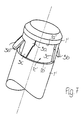
- the securing element denoted overall by 3
- the circumferential element area 3a is therefore interrupted training. It has several spring tongues 3b which are bent radially outwards at an obtuse angle ⁇ are. Also go from the surrounding element area Support areas 3c from that as tongues or tabs are trained.
- they are tongues or tab-shaped support areas 3c with respect to the circumferential element area 3a is not bent or kinked.
- FIGS. 1b to 4b corresponds to essential to the embodiment of Figures 1 to 4.
- the annular securing element 3 is only the location the support areas designed as tongues or tabs 3c "and the spring tongues 3b" compared to the first embodiment changed.
- FIG 5 is a wave-shaped, circular-cylindrical area 1 provided that the offset area of a stub shaft forms.
- the circular cylindrical region 1 has a circumferential groove 1c, which has end walls that as contact surfaces 1a and 1b for the appropriate areas of the Securing element 3 serve. Is on the contact surface 1a the end edge of the element area 3a, on the contact surface 1b are the end faces of the flaps Support areas 3c.
- the installation of the securing element 3 is carried out by a transverse to the axis of symmetry 10 Slide the securing element onto the bottom of the Groove 1c.
- the outer contour of the peripheral element area 3a lies just like the outer contour of the support areas 3c the outer contour of the circular cylindrical region 1.
- the outer contour of the circular cylindrical area 1b corresponds the diameter 2a of a plate 2 Counter region 2.
- the circular cylindrical region 1 is in Direction of arrow VI according to Figure 5 through the hole 2a so shifted far until the shoulder 1d of the shaft end the bottom of 2 is applied.
- the distance between the Shoulder ld and the contact surface 1b for the support areas 3c corresponds approximately in the illustrated embodiment the thickness d of the plate-shaped counter region 2.
- the plate-shaped counter region 2 is in its position Figure 6 by the securing element 3 in the axial direction securely secured on the stub of the wave because the Grip the spring tongues 3b to the side of the hole 2a.
- Figure 7 shows a circular cylindrical region 1 ', which as Shaft stub is designed without a paragraph and only one groove 1c with the two system surfaces 1a 'and 1b'.
- this groove 1c ' the securing element 3 is installed in such a way as already described.
- Figure 8 shows another, as a stub shaft without paragraph trained circular cylindrical area 1 "with a circumferential Groove 1c ", which is deeper than the groove 1c 'according to the figure 7.
- this deeper groove is the total designated 3 ' Securing element used, which in Figures 1a to 4a.
- the support areas 3c ' are included bent radially inward and lie at the bottom of the groove 1c " on. So with this solution is the surrounding element area 3a 'with a radial distance from the bottom of the groove 1c "arranged.
- Figure 9 shows a solution with a circular cylindrical area 1 ", which corresponds to the circular cylindrical area according to FIG. 7 corresponds. Different from Figure 7 is in Figure 9 only the design of the securing element, the total designated 3 "and shown in Figures 1b to 4b is.
Landscapes
- Engineering & Computer Science (AREA)
- General Engineering & Computer Science (AREA)
- Mechanical Engineering (AREA)
- Snaps, Bayonet Connections, Set Pins, And Snap Rings (AREA)
Description
- Figur 1 -
- eine perspektivische Ansicht einer ersten Ausführungsform des Sicherungselements,
- Figur 2 -
- eine Seitenansicht des Sicherungselements gemäß Figur 1,
- Figur 3 -
- eine Unteransicht des Sicherungselements gemäß Pfeil III in Figur 2,
- Figur 4 -
- eine Seitenansicht einer Abwicklung des Sicherungselements gemäß Figur 1,
- Figur 1a -
- eine Figur 1 entsprechende Darstellung einer zweiten Ausführungsform,
- Figur 2a -
- eine Figur 2 entsprechende Darstellung einer zweiten Ausführungsform,
- Figur 3a -
- eine Figur 3 entsprechende Darstellung einer zweiten Ausführungsform,
- Figur 4a -
- eine Figur 4 entsprechende Darstellung einer zweiten Ausführungsform,
- Figur 1b -
- eine Figur 1 entsprechende Darstellung einer dritten Ausführungsform,
- Figur 2b -
- eine Figur 2 entsprechende Darstellung einer dritten Ausführungsform,
- Figur 3b -
- eine Figur 3 entsprechende Darstellung einer dritten Ausführungsform,
- Figur 4b -
- eine Figur 4 entsprechende Darstellung einer dritten Ausführungsform,
- Figur 5 -
- eine perspektivische Explosionsdarstellung zweier zusammenzufügender Teile mit einem Sicherungsring gemäß Figur 1,
- Figur 6 -
- die Anordnung gemäß Figur 5 in Montageposition, wobei zur Verdeutlichung der Einbaulage ein Segment des die Durchgangsbohrung aufweisenden plattenförmigen Gegenbereichs weggeschnitten dargestellt ist,
- Figur 7 -
- die perspektivische Ansicht eines Wellenstummels mit einem Sicherungselement gemäß Figur 1,
- Figur 8 -
- eine perspektivische Ansicht eines Wellenstummels mit einem Sicherungselement gemäß Figur 1a,
- Figur 9 -
- die perspektivische Ansicht eines Wellenstummels mit einem Sicherungselement gemäß Figur 1b.
Claims (8)
- Ringförmiges Sicherungselement (3; 3'; 3") zum Festlegen eines umgriffenen, wellenförmigen, kreiszylindrischen Bereichs (1; 1'; 1") in Einbaulage gegenüber einem Gegenbereich (2), mit von einem umlaufenden Elementbereich (3a; 3a'; 3a") radial sich erstreckenden, angeformten Federzungen (3b; 3b'; 3b"), die gegenüber dem umlaufenden Elementbereich unter einem Winkel (α) geneigt angeordnet sind,
dadurch gekennzeichnet,
daß der umlaufende Elementbereich (3a; 3a'; 3a") unterbrochen und zur Anlage an eine erste Anlagefläche (1a; 1a'; 1a") des kreiszylindrischen Bereichs (1; 1'; 1") ausgebildet ist, wobei die Federzungen (3b; 3b'; 3b") sich radial auswärts erstrecken und am umlaufenden Elementbereich weiterhin Abstützbereiche (3c; 3c'; 3c") angeformt sind, die sich an einer zweiten Anlagefläche (1b; 1b'; 1b") des kreiszylindrischen Bereichs (1; 1'; 1") abstützen. - Ringförmiges Sicherungselement nach Anspruch 1,
dadurch gekennzeichnet,
daß es derart zum Einbau in eine umlaufende Nut (1c; 1c'; 1c") des kreiszylindrischen Bereichs (1, 1'; 1") ausgebildet ist, daß der umlaufende Elementbereich (3a, 3a'; 3a") zur Anlage an die von der stirnseitigen ersten Nutwand gebildete erste Anlagefläche (1a; 1a'; 1a") und die Abstützbereiche (3c; 3c'; 3c") zur Anlage an die von der stirnseitigen zweiten Nutwand gebildete zweite Anlagefläche (1b; 1b'; 1b") ausgebildet sind. - Ringförmiges Sicherungselement nach Anspruch 1 oder 2,
dadurch gekennzeichnet,
daß der unterbrochen umlaufende Elementbereich (3a; 3a'; 3a") kreiszylindrisch ausgebildet ist. - Ringförmiges Sicherungselement nach einem oder mehreren der Ansprüche 1 bis 3,
dadurch gekennzeichnet,
daß die Abstützbereiche (3c; 3c'; 3c") als sich zumindest annähernd in Achsrichtung des kreiszylindrischen umlaufenden Elementbereichs (3a; 3a'; 3a") erstreckende Zungen ausgebildet sind. - Ringförmiges Sicherungselement nach einem oder mehreren der Ansprüche 1 bis 4,
dadurch gekennzeichnet,
daß die Abstützbereiche (3c; 3c'; 3c") angeformte Federzungen sind. - Ringförmiges Sicherungselement nach einem oder mehreren der Ansprüche 1 bis 5,
dadurch gekennzeichnet,
daß die als Federzungen ausgebildeten Abstützbereiche (3c') radial einwärts abgeknickt sind. - Ringförmiges Sicherungselement nach einem oder mehreren der Ansprüche 1 bis 6,
dadurch gekennzeichnet,
daß die Abstützbereiche (3c, 3c'; 3c") und die Federzungen (3b; 3b'; 3b") gleichmäßig über den umlaufenden Elementbereich (3a; 3a'; 3a") verteilt angeordnet sind. - Ringförmiges Sicherungselement nach einem oder mehreren der Ansprüche 1 bis 7,
dadurch gekennzeichnet,
daß an den einander benachbarten Enden des umlaufenden Elementbereichs (3a; 3a') Abstützbereiche (3c; 3c') angeordnet sind.
Applications Claiming Priority (3)
| Application Number | Priority Date | Filing Date | Title |
|---|---|---|---|
| DE19647589 | 1996-11-18 | ||
| DE19647589A DE19647589C1 (de) | 1996-11-18 | 1996-11-18 | Ringförmiges Sicherungselement |
| PCT/EP1997/004321 WO1998022723A1 (de) | 1996-11-18 | 1997-08-08 | Ringförmiges sicherungselement |
Publications (2)
| Publication Number | Publication Date |
|---|---|
| EP0876556A1 EP0876556A1 (de) | 1998-11-11 |
| EP0876556B1 true EP0876556B1 (de) | 2001-05-09 |
Family
ID=7811962
Family Applications (1)
| Application Number | Title | Priority Date | Filing Date |
|---|---|---|---|
| EP97938888A Expired - Lifetime EP0876556B1 (de) | 1996-11-18 | 1997-08-08 | Ringförmiges sicherungselement |
Country Status (5)
| Country | Link |
|---|---|
| US (1) | US6116837A (de) |
| EP (1) | EP0876556B1 (de) |
| JP (1) | JP3261536B2 (de) |
| DE (2) | DE19647589C1 (de) |
| WO (1) | WO1998022723A1 (de) |
Families Citing this family (15)
| Publication number | Priority date | Publication date | Assignee | Title |
|---|---|---|---|---|
| US6679502B1 (en) * | 2001-08-28 | 2004-01-20 | Dana Corporation | Valve stem seal assembly with valve guide retainer |
| EP1515059B1 (de) * | 2003-09-09 | 2008-03-19 | BorgWarner Inc. | Einrichtung zur axialen Sicherung einer Kupplungseinrichtung an einer Drehdurchführung |
| US20050226685A1 (en) * | 2004-04-09 | 2005-10-13 | Golden Bridge Electech Inc. | Retention structure |
| US7264284B2 (en) * | 2005-09-29 | 2007-09-04 | Ming-Piao Hsu | Door catch |
| TW201514387A (zh) * | 2013-10-14 | 2015-04-16 | Wistron Corp | 固定機構與其接合組件 |
| CN104632813A (zh) * | 2013-11-12 | 2015-05-20 | 张造伦 | 多角型连接孔结构 |
| DE102014104191B3 (de) * | 2014-03-26 | 2015-09-10 | Thyssenkrupp Presta Aktiengesellschaft | Welle für eine Lenkung eines Kraftfahrzeugs |
| DE202015000344U1 (de) * | 2015-01-15 | 2016-04-18 | Grass Gmbh | Befestigungseinrichtung |
| EP3047951B1 (de) * | 2015-01-23 | 2017-03-08 | Bulten AB | Befestigungselement |
| GB201514614D0 (en) * | 2015-07-27 | 2015-09-30 | Trw Steering Systems Poland Sp Z O O | A steering column assembly |
| GB201604738D0 (en) * | 2016-03-04 | 2016-05-04 | Trw Steering Systems Poland Sp Z O O | A steering column assembly |
| FR3064035B1 (fr) * | 2017-03-16 | 2019-04-19 | Sogefi Air & Cooling | Manchon amovible pour le maintien et la fixation de vis |
| AT519878B1 (de) * | 2017-07-06 | 2018-11-15 | Ulrich Schluesselbauer | Vorrichtung zum Befestigen eines Steigbügels in einer Betonwand |
| CN109494596B (zh) * | 2019-01-03 | 2020-09-01 | 国网山东省电力公司淄博供电公司 | 一种环网柜防凝露无助力通风装置 |
| EP3933146B1 (de) * | 2020-07-01 | 2025-09-10 | Siemens Gamesa Renewable Energy A/S | Bolzensystem für verbindungsflansche |
Family Cites Families (14)
| Publication number | Priority date | Publication date | Assignee | Title |
|---|---|---|---|---|
| DE10907C (de) * | H. KOTTGEN in Bergisch-Gladbach | Schraubensicherung | ||
| US1083697A (en) * | 1913-03-17 | 1914-01-06 | Herman P Neptune | Tenon-fastener. |
| FR489665A (fr) * | 1917-12-03 | 1919-03-01 | Robert Horwood Fewster | Frein d'écrou |
| US2342910A (en) * | 1942-08-04 | 1944-02-29 | Tinnerman Products Inc | Fastening device |
| US2887891A (en) * | 1957-01-18 | 1959-05-26 | Perez Alicia Fernandez | Multi-unit drive pulley |
| US3050097A (en) * | 1959-10-22 | 1962-08-21 | United Carr Fastener Corp | Snap-in bolt retainer |
| JPS531429B1 (de) * | 1969-09-22 | 1978-01-19 | ||
| JPS5929414U (ja) * | 1982-08-18 | 1984-02-23 | マツダ株式会社 | ヒンジピン装置 |
| FR2594910B1 (fr) * | 1986-02-21 | 1988-08-12 | Mecafrance Sa | Rondelle de blocage pour ecrous |
| US4810145A (en) * | 1986-08-20 | 1989-03-07 | Villas Hugo J | Retractable and reusable self-locking fastener |
| JPH0453454Y2 (de) * | 1987-08-31 | 1992-12-16 | ||
| US5022875A (en) * | 1989-10-20 | 1991-06-11 | Brunswick Corporation | Marine propeller locking tab washer |
| JPH0468211U (de) * | 1990-10-24 | 1992-06-17 | ||
| JPH0642514A (ja) * | 1992-07-21 | 1994-02-15 | Masao Kubota | 止め輪 |
-
1996
- 1996-11-18 DE DE19647589A patent/DE19647589C1/de not_active Expired - Fee Related
-
1997
- 1997-08-08 WO PCT/EP1997/004321 patent/WO1998022723A1/de not_active Ceased
- 1997-08-08 DE DE59703505T patent/DE59703505D1/de not_active Expired - Lifetime
- 1997-08-08 JP JP51995498A patent/JP3261536B2/ja not_active Expired - Fee Related
- 1997-08-08 US US09/068,078 patent/US6116837A/en not_active Expired - Fee Related
- 1997-08-08 EP EP97938888A patent/EP0876556B1/de not_active Expired - Lifetime
Also Published As
| Publication number | Publication date |
|---|---|
| WO1998022723A1 (de) | 1998-05-28 |
| US6116837A (en) | 2000-09-12 |
| JP3261536B2 (ja) | 2002-03-04 |
| EP0876556A1 (de) | 1998-11-11 |
| DE19647589C1 (de) | 1998-02-26 |
| DE59703505D1 (de) | 2001-06-13 |
| JPH11504418A (ja) | 1999-04-20 |
Similar Documents
| Publication | Publication Date | Title |
|---|---|---|
| DE60105206T2 (de) | Scheibe aus verbundwerkstoff für eine scheibenbremse | |
| DE19647589C1 (de) | Ringförmiges Sicherungselement | |
| DE3044415C2 (de) | Elastische Kupplung zur Übertragung einer Drehbewegung | |
| DE2303051B2 (de) | Lagerhülse | |
| DE2705690A1 (de) | Fahrzeugaufhaengungsvorrichtung | |
| DE2830818C2 (de) | Einsetzbarer Bordring für ein Radialwälzlager | |
| DE3515116C2 (de) | ||
| CH650572A5 (de) | Dichtungseinheit. | |
| EP0842081B1 (de) | Lageveränderliche stirnseitige einspannung eines ringkörpers | |
| DE69622128T2 (de) | Vorrichtung zur Befestigung eines Elementes, insbesondere eines Rohres, an einer Wand | |
| DE2602002A1 (de) | Sicherungs- und/oder distanzring | |
| DE19929536C1 (de) | Anordnung zur axialen Festlegung des Ringes eines Lagers | |
| DE102011107352A1 (de) | Ringfilter für flüssige oder gasförmige Medien | |
| DE2344854B2 (de) | Radgewicht für Fahrzeuge | |
| EP0984183B1 (de) | Flexible Ganzstahl-Wellen-Kupplung | |
| DE2357374A1 (de) | Trockenrasierapparat i | |
| DE3513315C2 (de) | ||
| DE3732895C2 (de) | ||
| DE3418993C2 (de) | Innenspannsatz | |
| DE3527053C2 (de) | ||
| DE3804560A1 (de) | Reibschluessig wirkender sicherungsring | |
| DE19845949A1 (de) | Kunststoffhülse für eine Lagervorrichtung | |
| DE19962560C2 (de) | Axiale Sicherungsscheibe und damit ausgestattete Antriebseinheit | |
| DE3816732C2 (de) | ||
| DE2360803C3 (de) | Rückschlagventil |
Legal Events
| Date | Code | Title | Description |
|---|---|---|---|
| PUAI | Public reference made under article 153(3) epc to a published international application that has entered the european phase |
Free format text: ORIGINAL CODE: 0009012 |
|
| 17P | Request for examination filed |
Effective date: 19971220 |
|
| AK | Designated contracting states |
Kind code of ref document: A1 Designated state(s): DE FR GB IT |
|
| GRAG | Despatch of communication of intention to grant |
Free format text: ORIGINAL CODE: EPIDOS AGRA |
|
| GRAG | Despatch of communication of intention to grant |
Free format text: ORIGINAL CODE: EPIDOS AGRA |
|
| GRAH | Despatch of communication of intention to grant a patent |
Free format text: ORIGINAL CODE: EPIDOS IGRA |
|
| 17Q | First examination report despatched |
Effective date: 20000831 |
|
| GRAH | Despatch of communication of intention to grant a patent |
Free format text: ORIGINAL CODE: EPIDOS IGRA |
|
| RAP1 | Party data changed (applicant data changed or rights of an application transferred) |
Owner name: FAURECIA AUTOSITZE GMBH & CO. KG |
|
| GRAA | (expected) grant |
Free format text: ORIGINAL CODE: 0009210 |
|
| AK | Designated contracting states |
Kind code of ref document: B1 Designated state(s): DE FR GB IT |
|
| GBT | Gb: translation of ep patent filed (gb section 77(6)(a)/1977) |
Effective date: 20010509 |
|
| REF | Corresponds to: |
Ref document number: 59703505 Country of ref document: DE Date of ref document: 20010613 |
|
| ITF | It: translation for a ep patent filed | ||
| ET | Fr: translation filed | ||
| REG | Reference to a national code |
Ref country code: GB Ref legal event code: IF02 |
|
| PLBE | No opposition filed within time limit |
Free format text: ORIGINAL CODE: 0009261 |
|
| STAA | Information on the status of an ep patent application or granted ep patent |
Free format text: STATUS: NO OPPOSITION FILED WITHIN TIME LIMIT |
|
| 26N | No opposition filed | ||
| PGFP | Annual fee paid to national office [announced via postgrant information from national office to epo] |
Ref country code: IT Payment date: 20080826 Year of fee payment: 12 Ref country code: FR Payment date: 20080822 Year of fee payment: 12 |
|
| PGFP | Annual fee paid to national office [announced via postgrant information from national office to epo] |
Ref country code: GB Payment date: 20080826 Year of fee payment: 12 |
|
| PGFP | Annual fee paid to national office [announced via postgrant information from national office to epo] |
Ref country code: DE Payment date: 20090907 Year of fee payment: 13 |
|
| GBPC | Gb: european patent ceased through non-payment of renewal fee |
Effective date: 20090808 |
|
| REG | Reference to a national code |
Ref country code: FR Ref legal event code: ST Effective date: 20100430 |
|
| PG25 | Lapsed in a contracting state [announced via postgrant information from national office to epo] |
Ref country code: FR Free format text: LAPSE BECAUSE OF NON-PAYMENT OF DUE FEES Effective date: 20090831 |
|
| PG25 | Lapsed in a contracting state [announced via postgrant information from national office to epo] |
Ref country code: GB Free format text: LAPSE BECAUSE OF NON-PAYMENT OF DUE FEES Effective date: 20090808 |
|
| PG25 | Lapsed in a contracting state [announced via postgrant information from national office to epo] |
Ref country code: IT Free format text: LAPSE BECAUSE OF NON-PAYMENT OF DUE FEES Effective date: 20090808 |
|
| REG | Reference to a national code |
Ref country code: DE Ref legal event code: R119 Ref document number: 59703505 Country of ref document: DE Effective date: 20110301 |
|
| PG25 | Lapsed in a contracting state [announced via postgrant information from national office to epo] |
Ref country code: DE Free format text: LAPSE BECAUSE OF NON-PAYMENT OF DUE FEES Effective date: 20110301 |