EP0875810A2 - Méthode et dispositif de surveillance d'une installation comprenant plusieurs unités fonctionnelles - Google Patents
Méthode et dispositif de surveillance d'une installation comprenant plusieurs unités fonctionnelles Download PDFInfo
- Publication number
- EP0875810A2 EP0875810A2 EP98107462A EP98107462A EP0875810A2 EP 0875810 A2 EP0875810 A2 EP 0875810A2 EP 98107462 A EP98107462 A EP 98107462A EP 98107462 A EP98107462 A EP 98107462A EP 0875810 A2 EP0875810 A2 EP 0875810A2
- Authority
- EP
- European Patent Office
- Prior art keywords
- safety
- safety devices
- security
- inputs
- relevant
- Prior art date
- Legal status (The legal status is an assumption and is not a legal conclusion. Google has not performed a legal analysis and makes no representation as to the accuracy of the status listed.)
- Granted
Links
Images

Classifications
-
- G—PHYSICS
- G05—CONTROLLING; REGULATING
- G05B—CONTROL OR REGULATING SYSTEMS IN GENERAL; FUNCTIONAL ELEMENTS OF SUCH SYSTEMS; MONITORING OR TESTING ARRANGEMENTS FOR SUCH SYSTEMS OR ELEMENTS
- G05B19/00—Program-control systems
- G05B19/02—Program-control systems electric
- G05B19/418—Total factory control, i.e. centrally controlling a plurality of machines, e.g. direct or distributed numerical control [DNC], flexible manufacturing systems [FMS], integrated manufacturing systems [IMS] or computer integrated manufacturing [CIM]
-
- G—PHYSICS
- G05—CONTROLLING; REGULATING
- G05B—CONTROL OR REGULATING SYSTEMS IN GENERAL; FUNCTIONAL ELEMENTS OF SUCH SYSTEMS; MONITORING OR TESTING ARRANGEMENTS FOR SUCH SYSTEMS OR ELEMENTS
- G05B19/00—Program-control systems
- G05B19/02—Program-control systems electric
- G05B19/18—Numerical control [NC], i.e. automatically operating machines, in particular machine tools, e.g. in a manufacturing environment, so as to execute positioning, movement or co-ordinated operations by means of program data in numerical form
- G05B19/406—Numerical control [NC], i.e. automatically operating machines, in particular machine tools, e.g. in a manufacturing environment, so as to execute positioning, movement or co-ordinated operations by means of program data in numerical form characterised by monitoring or safety
-
- G—PHYSICS
- G05—CONTROLLING; REGULATING
- G05B—CONTROL OR REGULATING SYSTEMS IN GENERAL; FUNCTIONAL ELEMENTS OF SUCH SYSTEMS; MONITORING OR TESTING ARRANGEMENTS FOR SUCH SYSTEMS OR ELEMENTS
- G05B23/00—Testing or monitoring of control systems or parts thereof
-
- Y—GENERAL TAGGING OF NEW TECHNOLOGICAL DEVELOPMENTS; GENERAL TAGGING OF CROSS-SECTIONAL TECHNOLOGIES SPANNING OVER SEVERAL SECTIONS OF THE IPC; TECHNICAL SUBJECTS COVERED BY FORMER USPC CROSS-REFERENCE ART COLLECTIONS [XRACs] AND DIGESTS
- Y02—TECHNOLOGIES OR APPLICATIONS FOR MITIGATION OR ADAPTATION AGAINST CLIMATE CHANGE
- Y02P—CLIMATE CHANGE MITIGATION TECHNOLOGIES IN THE PRODUCTION OR PROCESSING OF GOODS
- Y02P90/00—Enabling technologies with a potential contribution to greenhouse gas [GHG] emissions mitigation
- Y02P90/02—Total factory control, e.g. smart factories, flexible manufacturing systems [FMS] or integrated manufacturing systems [IMS]
Definitions
- the invention relates to a method and a device for monitoring a system with several functional units, like a manufacturing plant.
- a machine or a robot In a plant, such as a manufacturing plant, of which the Invention starts, it can be one or more associated machines act, such as Robot.
- a machine or a robot consists of several different functional units, such as the Power section of a control unit and one Control unit. In a plant from which it started several such machines can be used with the aforementioned Functional units work together and with each other be linked.
- Peripherals may also be present like rails on which the machines, like robots, be moved or a portal that the machines or Robots along a "workpiece" to be machined, such as of a ship.
- the invention is therefore based on the object To create methods and an apparatus by means of which in a simple, clear manner an increase in Security in a complex system like the one above was outlined, can be achieved.
- each Functional unit individually with its own redundant, two-channel safety devices checked the security directions continuously over each other inform her of her review status and at a Malfunction of at least one functional unit or Safety device a safety-relevant actuator is operated.
- each functional unit is its own assigned redundant, two-channel safety device and the safety devices are so together connected that they malfunction at least a functional unit or safety device Actuate at least one safety-related actuator.
- the invention provides a distributed security logic, where every safety device has all the necessary Has security functions. This is one high-resolution diagnosis possible.
- the safety devices are connected or communicate with each other with each other so that they also monitor each other can and a safety device the failure another recognizes and thus a security-relevant Output signal for actuating an actuator.
- the safety devices have a controller core and have an interface circuit.
- the safety devices can be very simple and be clearly structured.
- the safety devices communicate with each other in series or that the safety devices are serial are interconnected. Through the serial connection parallel wiring becomes superfluous. Necessary Cable cross sections can be reduced, which in particular for portable devices, such as operating or programming handheld devices, is extremely advantageous.
- the safety devices using a ring protocol communicate with each other or that the safety devices are connected in a ring.
- the addressing can be physical by placing on the bus. A safe one The reaction is also when the ring protocol is expanded immediately available.
- each safety device has at least one microprocessor. According to a preferred development, it is provided that each safety device has at least two microprocessors having. See further preferred configurations before any safety device diagnostic inputs has, in particular the diagnostic inputs with Test switching cycles of the safety-relevant inputs are synchronized or the safety devices ongoing diagnosis of the functional units assigned to them and thus carry out the system.
- any safety device diagnostic inputs has, in particular the diagnostic inputs with Test switching cycles of the safety-relevant inputs are synchronized or the safety devices ongoing diagnosis of the functional units assigned to them and thus carry out the system.
- any safety device diagnostic inputs has, in particular the diagnostic inputs with Test switching cycles of the safety-relevant inputs are synchronized or the safety devices ongoing diagnosis of the functional units assigned to them and thus carry out the system.
- any safety device diagnostic inputs has, in particular the diagnostic inputs with Test switching cycles of the safety-relevant inputs are synchronized or the safety devices ongoing diagnosis of the functional units assigned to them and thus carry out the system.
- microprocessors contained in the safety devices cyclically your processor image and the calculated from it Check result and / or content of memories, in particular the correct connection and function is checked by signal inputs and signal transmitters. Due to the redundant design of the safety devices in the manner outlined above Microprocessors each other and the surrounding Check the hardware cyclically, at the same time the expiring Program can be checked for consistency. Of the The content of the processors is compared with one Ring protocol over the entire ring.
- each safety device at least has a safety-related output and / or that each safety device has several safety-relevant ones Has inputs.
- Both the entire security structure becomes simple and Particularly inexpensive if planned for further training is that the safety devices are identical to each other are formed, preferably also in the Basic software integrated into identical safety devices is identical and adjustments only about Soft blocks or switches are made.
- the inventive method and the inventive Solution have significant advantages.
- the ring structure the entire monitoring device is only closed, if all functional units and assigned to them individual safety devices in operation are located. Communication is interrupted when one Safety device shows a malfunction; at a such an ongoing disturbance is switched off and the entire system enters a safe state.
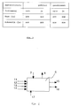
- a device is used for monitoring a plant A, such as a manufacturing plant; such has, for example, a power unit 1 which Power electronics and the mechanical elements of a Machine or a robot.
- the power unit 1 is assigned a control unit, which Signal electronics for controlling the power unit 1 contains and as a pure hardware circuit or in the desired Gradation with software elements up to one pure computer control, can be trained.
- a robot is power unit 1 and control unit 2 usually physically and spatially separated designed.
- a system from which the invention is based can also have an operating unit 3, for example can be a handheld programming device that specific case for programming a robot like the one Control unit 2 can serve and in such a case also spatially and physically separate from this is trained.
- peripherals 4, 5 have, such as a moving device for the power unit (Power Module) 1 or for example in shipbuilding a portal on which several performance units 1 are arranged.
- Power Module Power Module
- a safety device 6 has (at least) two microcontrollers. These have sufficient integrated RAMs or ROMs and at least one serial Connection (point). So the dual channel of the Safety circles up to the evaluation be preserved. The two channels of the redundant system are constantly compared. Depending on the use is one different interface wiring provided.
- the safety devices 6.1-6.5 are above incoming and forwarding interfaces or lines 7, 8 in connection. The connection is preferred still in a ring structure with outgoing and return lines 7, 8 formed.
- a safety device 6 has in addition to the serial connections or lines 7, 8 for Connection with the other security devices safety-relevant inputs 10-14 which are connected to the respective functional unit and individual controls the same are connected and more security-relevant for reading Serve signals.
- Security relevant Inputs either initiate a stop or are a condition for such a stop.
- the inputs 11-14 are double, so each microcontroller via an independent input with identical function disposes. Inputs without a safety function can also be used be provided. These are also called diagnostic inputs designated and have different on both controllers Meaning. All safety-relevant inputs 11-14 are evaluated in parallel by both microcontrollers. So an entrance with an approval button, another with an emergency stop button and another with a selection button for test or automatic mode connected be.
- the operator protection input - locking (for techn. Protective measures) - only sets the safety cell itself quiet.
- the area is under the safety cell understood that drive through dangerous by a kinematics can be. For a robot cell this is e.g. the working area of the robot limited by protective fences itself as well as the additional axles, the dangerous Can perform movements.
- the pending operator protection signal is synonymous with the closed Protective fence of the security cell.
- the input 13 for test / automatic is a qualifying signal.
- test mode operator protection is switched off and the approval buttons are active.
- Operator protection is active in the automatic mode, and the consent buttons are not queried.
- the safety cell can either be in the test or automatic mode. Neither of the two operating modes are possible at the same time as neither operating mode.
- the closed-circuit principle is difficult to adhere to here because both settings are active settings. It is therefore advisable to use counter-parallel levels.
- the result is that the signal is read in by the ⁇ controllers once as automatic and once as / automatic .
- the term Test is used instead of the name / automatic .
- Safety-relevant outputs are those whose proper function for switching off the system energy is imperative.
- the safety-relevant outputs include the control for the network protection of the drives by the drives one signal. This output is available on every safety device and is safe.
- the emergency stop exit has the task of making a local emergency stop request into the emergency loop of a complete system loop in. To get potential-free contacts, becomes the node with a safe relay combination fitted.
- Operator protection means facilities for Protection of the operator These include protective fences, their Monitoring and depending on the operating mode also the Enabling switch. All outputs are in the node such facilities summarized. The operator protection output has the task of violating operator protection also effective for plant components involved do. To get potential-free contacts, a safe relay combination is connected to the nodes will.
- Informal or control inputs 17 are those that are necessary for the correct operation of the robot. These inputs are not safety-relevant and can can be used freely. They just provide information available for diagnostic purposes. The inputs are synchronized with the test switching cycles of the safety-relevant Signals. This also enables linked emergency stop buttons between the contacts.
- the "Activate drives” signal is an impulse that the Actuators should switch on as long as there is no safety requirement speaks against it. This signal must not be kept constantly active.
- Actuators enable AF
- the "drives enable” signal has the task of Switch off drives by removing or switching on to prevent.
- a local emergency stop or operator protection loop can tapped with these inputs between contacts to provide information about to get the location of the security request.
- Informal exits are the ones that are spent to represent the status of the security network. Informal outputs can go to a register interface be summarized. When connecting one Control computer, in which no safety-relevant Actuators are available, can also be safety-related Outputs can be used for information purposes.
- the emergency stop information has the task of reporting a local emergency stop request to a controller or signal lamp.
- This signal is an OR operation of all emergency stop conditions with the exception of the signal: external emergency stop request .
- the error signal provides information as to whether it is within the KU-SIBA network has made a mistake that leads to Shutdown has resulted.
- a safety device in the control unit 2 there are all information and states of the safety circuit the control software.
- an exit will be assigned an emergency stop by one trigger such in the control unit 2.
- a safety device 6.1 in an operating unit 3 is mainly the carrier of signaling devices for emergency stop, Operating mode selection and switching the drives on and off.
- a display can be made via control software and a display respectively.
- Safety devices 6.4 and 6.5 in the periphery 4, 5 can drive energy for integrated in a protection circuit Operate the servo switch and signal transmitter such as Extended light curtains and additional emergency stop button Integrate kinematics into the protective circuit.
- the display can be an identical security device can also be integrated into corresponding control panels.
- Fig. 3 are the operating states of the safety devices according to the invention shown.
- Operator protection can be open or closed.
- An consent key can be pressed (yes) or not be actuated (no). It can be an automatic or test mode be chosen. In automatic mode is how from the list, operation is only possible if operator protection is closed. If "test” is selected operation with operator protection open and closed possible, but only if the consent button is pressed at the same time is operated.
- the operating states can with regard to further inputs depending on the purpose of use.
- the information channel used for the comparison is the same serial channel that is used for the Communication between security devices is used.
- a comparison is made during ongoing process communication: One step corresponds to the amount of data one Microcontrollers. A sliding step, it depends on the position of the microcontroller of the safety device the first or the last one per communication, is for provided the comparison. In this step it will Input and output image with that of the parallel Microcontrollers in the same security device compared.
- each microcontroller transmits own process data.
- the second microcontroller a safety device can already to compare.
- the first microcontroller The process image of the previous microcontroller is first noted. He makes the comparison after the second Sliding step through.
- the VF counter of this microcontroller therefore applies to the one previously arranged in the safety circuit Security core.
- a link is made as the actual one Function of the Schierheit Vietnamese: On the one hand, the Inputs of each individual safety device own result formed; second, the results the other security devices before upgrading taken into account in the local result. There are two ways to determine the output results: The entire process image can be used for communication be exchanged and thus in each of the total emergency parallel, but linked in different order will. An execution command can be sent. In all safety devices link this command their results and there will be all exits after this Command switched.
- the emergency stop function can be used by various signal generators to be triggered. All connected signal transmitters are connected via two channels. When releasing the emergency stop lock can be infinite simultaneity between the channels.
- the emergency stop has different operating modes Reactions.
- the shutdown of the network is in automatic mode delayed and safe.
- the initiated emergency stop is from recognized by the control system and an emergency stop ramp is activated immediately hazards. With this stop ramp the remains Robots on the programmed path. The robot comes in a calculated point to a standstill.
- Communication between security devices is serial and goes through both microcontrollers through so that each microcontroller is able to the other via the communication ring Provide process image for comparison.
- the Communication is used to compare the channels in two-channel Inputs and for deterministic updating of the output image on the entire bus.
- Each Communication takes place in sliding steps.
- a step corresponds to the data volume of a microcontroller.
- a Sliding step it's the first or the last pro Communication is intended for comparison. All other sliding steps are used to map the overall process of the network in the individual security device to determine. Only process images are used taken over by others, which of their two Controllers were immediately transferred.
Landscapes
- Engineering & Computer Science (AREA)
- Physics & Mathematics (AREA)
- General Physics & Mathematics (AREA)
- Automation & Control Theory (AREA)
- Manufacturing & Machinery (AREA)
- General Engineering & Computer Science (AREA)
- Quality & Reliability (AREA)
- Human Computer Interaction (AREA)
- Safety Devices In Control Systems (AREA)
- Emergency Alarm Devices (AREA)
Applications Claiming Priority (2)
| Application Number | Priority Date | Filing Date | Title |
|---|---|---|---|
| DE19718284 | 1997-05-01 | ||
| DE19718284A DE19718284C2 (de) | 1997-05-01 | 1997-05-01 | Verfahren und Vorrichtung zum Überwachen einer Anlage mit mehreren Funktionseinheiten |
Publications (3)
| Publication Number | Publication Date |
|---|---|
| EP0875810A2 true EP0875810A2 (fr) | 1998-11-04 |
| EP0875810A3 EP0875810A3 (fr) | 2000-03-22 |
| EP0875810B1 EP0875810B1 (fr) | 2002-08-14 |
Family
ID=7828233
Family Applications (1)
| Application Number | Title | Priority Date | Filing Date |
|---|---|---|---|
| EP98107462A Expired - Lifetime EP0875810B1 (fr) | 1997-05-01 | 1998-04-23 | Méthode et dispositif de surveillance d'une installation comprenant plusieurs unités fonctionnelles |
Country Status (7)
| Country | Link |
|---|---|
| US (1) | US6385562B1 (fr) |
| EP (1) | EP0875810B1 (fr) |
| JP (1) | JP4080060B2 (fr) |
| KR (1) | KR100553274B1 (fr) |
| CN (1) | CN1068682C (fr) |
| DE (2) | DE19718284C2 (fr) |
| RU (1) | RU2175451C2 (fr) |
Cited By (3)
| Publication number | Priority date | Publication date | Assignee | Title |
|---|---|---|---|---|
| EP1396771B1 (fr) * | 2001-05-31 | 2016-02-17 | Omron Corporation | Unité esclave et système de réseau procède de traitement esclave procède de collecte d'informations sur un appareil |
| AT521134B1 (de) * | 2018-04-20 | 2019-11-15 | Engel Austria Gmbh | Industrieanlage |
| RU2710502C1 (ru) * | 2019-04-22 | 2019-12-26 | Игорь Давидович Долгий | Унифицированный логический контроллер |
Families Citing this family (43)
| Publication number | Priority date | Publication date | Assignee | Title |
|---|---|---|---|---|
| DE19718284C2 (de) | 1997-05-01 | 2001-09-27 | Kuka Roboter Gmbh | Verfahren und Vorrichtung zum Überwachen einer Anlage mit mehreren Funktionseinheiten |
| DE19905841A1 (de) * | 1999-02-12 | 2000-08-24 | Kuka Roboter Gmbh | Vorrichtung zum Verarbeiten sicherheitsrelevanter Daten |
| DE19920340A1 (de) * | 1999-05-03 | 2000-11-09 | Hsm Pressen Gmbh & Co Kg | Steuerungsvorrichtung und Verfahren zur Steuerung sicherheitsrelevanter Funktionen einer gefahrbringenden Maschine |
| DE19925693B4 (de) * | 1999-06-04 | 2007-05-16 | Phoenix Contact Gmbh & Co | Schaltungsanordnung zur gesicherten Datenübertragung in einem ringförmigen Bussystem |
| DE19927635B4 (de) * | 1999-06-17 | 2009-10-15 | Phoenix Contact Gmbh & Co. Kg | Sicherheitsbezogenes Automatisierungsbussystem |
| US6795798B2 (en) * | 2001-03-01 | 2004-09-21 | Fisher-Rosemount Systems, Inc. | Remote analysis of process control plant data |
| US7430451B2 (en) * | 2001-05-31 | 2008-09-30 | Omron Corporation | Safety unit, controller system, connection method of controllers, control method of the controller system and monitor method of the controller system |
| EP1406134B1 (fr) * | 2001-06-22 | 2010-10-06 | Omron Corporation | Systeme de reseau securise, esclave securise et controleur securise |
| DE10236843A1 (de) * | 2002-08-08 | 2004-03-04 | Volkswagen Ag | Bereitstellung und Aufbereitung aktueller Prozess- und Produktinformationen |
| DE10240584A1 (de) * | 2002-08-28 | 2004-03-11 | Pilz Gmbh & Co. | Sicherheitssteuerung zum fehlersicheren Steuern von sicherheitskritischen Prozessen sowie Verfahren zum Aufspielen eines neuen Betriebsprogrammes auf eine solche |
| US7515389B2 (en) * | 2003-02-28 | 2009-04-07 | Gottwald Port Technology Gmbh | Method and device for safely disconnecting electric drives |
| DE10314025B4 (de) * | 2003-03-28 | 2010-04-01 | Kuka Roboter Gmbh | Verfahren und Vorrichtung zum Steuern einer Mehrzahl von Handhabungsgeräten |
| DE10330916A1 (de) † | 2003-07-04 | 2005-02-03 | Pilz Gmbh & Co. Kg | Vorrichtung und Verfahren zum automatisierten Steuern eines Betriebsablaufs bei einer technischen Anlage |
| US7610119B2 (en) * | 2003-07-08 | 2009-10-27 | Omron Corporation | Safety controller and system using same |
| WO2005062144A1 (fr) | 2003-12-18 | 2005-07-07 | Matsushita Electric Industrial Co., Ltd. | Dispositif robotise |
| DE102004020830B4 (de) | 2004-02-19 | 2010-06-10 | Lenze Automation Gmbh | Sicherheits-Schaltungsverbund mit Ringkonzept für Steuergeräte der Leistungselektronik |
| US8000837B2 (en) | 2004-10-05 | 2011-08-16 | J&L Group International, Llc | Programmable load forming system, components thereof, and methods of use |
| JP3918950B2 (ja) * | 2005-04-19 | 2007-05-23 | オムロン株式会社 | セーフティデバイス |
| WO2007014725A1 (fr) * | 2005-08-02 | 2007-02-08 | Phoenix Contact Gmbh & Co. Kg | Commutateur de securite pour commander un dispositif relevant de la securite, afin de le mettre dans un etat de securite |
| DE102006012042A1 (de) * | 2006-03-16 | 2007-09-20 | Kuka Roboter Gmbh | Steuervorrichtung zur fehlersicheren Steuerung einer Maschine |
| CN101056216B (zh) * | 2006-04-10 | 2011-02-02 | 华为技术有限公司 | 一种测试系统和测试方法 |
| DE102006022889A1 (de) * | 2006-05-15 | 2007-11-22 | Kuka Roboter Gmbh | Gelenkroboter |
| EP1927440A1 (fr) * | 2006-11-30 | 2008-06-04 | Abb Research Ltd. | Procédé et dispositif de contrôle des conditions d'un robot industriel |
| DE102007024209A1 (de) * | 2007-05-24 | 2008-11-27 | Deutsches Zentrum für Luft- und Raumfahrt e.V. | Industrieroboter-Anordnung |
| DE102008029948B4 (de) * | 2008-06-26 | 2018-08-30 | Phoenix Contact Gmbh & Co. Kg | Überwachungssystem |
| ATE540343T1 (de) | 2009-10-23 | 2012-01-15 | Sick Ag | Sicherheitssteuerung |
| EP2362408B1 (fr) * | 2010-02-19 | 2017-04-05 | Rockwell Automation Germany GmbH & Co. KG | Dispositif d'interrupteur de sécurité avec entrée de signal universelle |
| DE102010047641B4 (de) | 2010-10-06 | 2022-06-15 | Kuka Roboter Gmbh | Steuerung eines Roboters |
| US8587320B2 (en) * | 2010-11-09 | 2013-11-19 | Honeywell International Inc. | System and method for testing a secondary servo control circuit in a redundant control configuration |
| US9529348B2 (en) | 2012-01-24 | 2016-12-27 | Emerson Process Management Power & Water Solutions, Inc. | Method and apparatus for deploying industrial plant simulators using cloud computing technologies |
| JP5894516B2 (ja) * | 2012-10-05 | 2016-03-30 | 株式会社日立製作所 | 制御システム |
| MX354053B (es) | 2013-05-13 | 2018-02-09 | Vorne Ind Inc | Método y sistema para la organización y almacenamiento de información de un proceso de fabricación. |
| US10185291B2 (en) * | 2013-06-28 | 2019-01-22 | Fisher Controls International Llc | System and method for shutting down a field device |
| JP6221605B2 (ja) * | 2013-10-08 | 2017-11-01 | 富士電機株式会社 | 安全制御装置および安全制御システム |
| JP6451323B2 (ja) * | 2015-01-06 | 2019-01-16 | 株式会社デンソーウェーブ | ロボットの配線方法 |
| DE102015011910A1 (de) * | 2015-09-11 | 2017-03-16 | Kuka Roboter Gmbh | Verfahren und System zum Steuern einer Roboteranordnung |
| US10534351B1 (en) | 2018-10-08 | 2020-01-14 | Quest Automated Services, LLC | Automation system network |
| US10326732B1 (en) | 2018-10-08 | 2019-06-18 | Quest Automated Services, LLC | Automation system with address generation |
| US10523673B1 (en) | 2018-10-08 | 2019-12-31 | Quest Automated Services, LLC | Automation system controller |
| CN113631328B (zh) * | 2019-04-02 | 2024-06-18 | 优傲机器人公司 | 用于机器人系统的可扩展安全系统 |
| RU2703681C1 (ru) * | 2019-04-19 | 2019-10-21 | Акционерное общество "ТеконГруп" | Модуль центрального процессора промышленного контроллера |
| TWI758926B (zh) * | 2020-10-27 | 2022-03-21 | 達明機器人股份有限公司 | 機器人安全監控系統及其診斷異常的方法 |
| DE102024123354A1 (de) * | 2024-08-15 | 2026-02-19 | Euchner Gmbh + Co. Kg | Sicherheitseinrichtung |
Family Cites Families (26)
| Publication number | Priority date | Publication date | Assignee | Title |
|---|---|---|---|---|
| DE2318072C3 (de) * | 1973-04-06 | 1982-10-21 | Licentia Patent-Verwaltungs-Gmbh, 6000 Frankfurt | System zur Überwachung und Fehlermeldung in sicherheitstechnischen Anlagen |
| US4092578A (en) * | 1976-12-03 | 1978-05-30 | Rockwell International Corporation | Elimination of voter caused deadzone |
| US4260942A (en) * | 1978-04-17 | 1981-04-07 | Trw Inc. | Failure detection and correction system for redundant control elements |
| US4596982A (en) * | 1983-02-14 | 1986-06-24 | Prime Computer, Inc. | Reconfigurable ring communications network |
| JPS59167710A (ja) * | 1983-03-14 | 1984-09-21 | Matsushita Electric Works Ltd | シ−ケンサのデ−タ転送方式 |
| JPS59212902A (ja) * | 1983-05-18 | 1984-12-01 | Hitachi Ltd | 多重化制御装置 |
| WO1986004432A1 (fr) * | 1985-01-22 | 1986-07-31 | National Can Corporation | Systeme redondant de commande pour machine automatique de formage |
| JPS6365509A (ja) * | 1986-09-05 | 1988-03-24 | Mitsubishi Electric Corp | 数値制御装置のデ−タ伝送装置 |
| GB2200476B (en) * | 1987-01-29 | 1991-02-06 | British Gas Plc | Monitor system |
| SU1418658A1 (ru) * | 1987-02-03 | 1988-08-23 | Ростовское высшее военное командно-инженерное училище ракетных войск им.Неделина М.И. | Устройство дл диагностировани взаимосв занных объектов |
| DE3706325A1 (de) * | 1987-02-27 | 1988-09-08 | Phoenix Elekt | Steuer- und datennetzwerk |
| US4918690A (en) * | 1987-11-10 | 1990-04-17 | Echelon Systems Corp. | Network and intelligent cell for providing sensing, bidirectional communications and control |
| US5055755A (en) * | 1989-05-31 | 1991-10-08 | Kabushiki Kaisha Toshiba | Distribution control apparatus |
| DE4041062A1 (de) * | 1990-12-20 | 1992-07-02 | Siemens Ag | Ueberwachungsschaltung fuer eine multiprozessoreinrichtung eines geraetes oder einer anlage |
| US5291416A (en) * | 1991-03-08 | 1994-03-01 | Software Algoritms Incorporated | Event feedback for numerically controlled machine tool and network implementation thereof |
| JPH0540516A (ja) * | 1991-05-28 | 1993-02-19 | Mori Seiki Co Ltd | Nc装置通信システム及びnc装置 |
| CH685125A5 (de) * | 1991-11-08 | 1995-03-31 | Rieter Ag Maschf | Spinnereianlage mit einem Prozessleitrechner. |
| DE4223435C2 (de) * | 1992-05-22 | 1994-06-01 | Ferag Ag | Sicherheitsabschaltsystem |
| CA2135718A1 (fr) * | 1993-11-15 | 1995-05-16 | Mark A. Gilbertie | Architecture de systeme electrique universelle pour applications de controle |
| DE4342991A1 (de) * | 1993-12-16 | 1995-06-22 | Bosch Gmbh Robert | Verfahren zum Überwachen wenigstens einer sicherheitsrelevanten Funktion eines Gerätes |
| US5491625A (en) * | 1993-12-23 | 1996-02-13 | The Dow Chemical Company | Information display system for actively redundant computerized process control |
| JP3297249B2 (ja) * | 1995-05-26 | 2002-07-02 | 三菱電機株式会社 | 分散型リモートi/o式制御システムの制御方法 |
| KR0185458B1 (ko) * | 1995-08-31 | 1999-05-15 | 토니 헬샴 | 제어부의 직렬통신장치 |
| JP3647955B2 (ja) * | 1996-01-23 | 2005-05-18 | 三菱電機株式会社 | 操作ボード、リモートi/o通信制御方法 |
| DE19620065C2 (de) * | 1996-05-20 | 2001-03-01 | Ifm Electronic Gmbh | Schaltungsanordnung zur Überwachung des fehlerfreien und/oder zur Erkennung eines fehlerbehafteten Zustands einer Anlage |
| DE19718284C2 (de) | 1997-05-01 | 2001-09-27 | Kuka Roboter Gmbh | Verfahren und Vorrichtung zum Überwachen einer Anlage mit mehreren Funktionseinheiten |
-
1997
- 1997-05-01 DE DE19718284A patent/DE19718284C2/de not_active Revoked
-
1998
- 1998-04-23 EP EP98107462A patent/EP0875810B1/fr not_active Expired - Lifetime
- 1998-04-23 DE DE59805151T patent/DE59805151D1/de not_active Expired - Lifetime
- 1998-04-28 US US09/066,914 patent/US6385562B1/en not_active Expired - Lifetime
- 1998-04-29 RU RU98108888/09A patent/RU2175451C2/ru active
- 1998-04-29 KR KR1019980015292A patent/KR100553274B1/ko not_active Expired - Lifetime
- 1998-04-30 JP JP12128198A patent/JP4080060B2/ja not_active Expired - Lifetime
- 1998-04-30 CN CN98107824A patent/CN1068682C/zh not_active Expired - Lifetime
Cited By (4)
| Publication number | Priority date | Publication date | Assignee | Title |
|---|---|---|---|---|
| EP1396771B1 (fr) * | 2001-05-31 | 2016-02-17 | Omron Corporation | Unité esclave et système de réseau procède de traitement esclave procède de collecte d'informations sur un appareil |
| AT521134B1 (de) * | 2018-04-20 | 2019-11-15 | Engel Austria Gmbh | Industrieanlage |
| AT521134A4 (de) * | 2018-04-20 | 2019-11-15 | Engel Austria Gmbh | Industrieanlage |
| RU2710502C1 (ru) * | 2019-04-22 | 2019-12-26 | Игорь Давидович Долгий | Унифицированный логический контроллер |
Also Published As
| Publication number | Publication date |
|---|---|
| JP4080060B2 (ja) | 2008-04-23 |
| DE59805151D1 (de) | 2002-09-19 |
| KR19980086661A (ko) | 1998-12-05 |
| US20020052717A1 (en) | 2002-05-02 |
| RU2175451C2 (ru) | 2001-10-27 |
| DE19718284C2 (de) | 2001-09-27 |
| US6385562B1 (en) | 2002-05-07 |
| EP0875810A3 (fr) | 2000-03-22 |
| CN1198375A (zh) | 1998-11-11 |
| EP0875810B1 (fr) | 2002-08-14 |
| JPH10320003A (ja) | 1998-12-04 |
| CN1068682C (zh) | 2001-07-18 |
| KR100553274B1 (ko) | 2006-06-14 |
| DE19718284A1 (de) | 1998-12-24 |
Similar Documents
| Publication | Publication Date | Title |
|---|---|---|
| EP0875810B1 (fr) | Méthode et dispositif de surveillance d'une installation comprenant plusieurs unités fonctionnelles | |
| DE19742716C5 (de) | Steuer- und Datenübertragungsanlage und Verfahren zum Übertragen von sicherheitsbezogenen Daten | |
| EP1738382B2 (fr) | Dispositif de commutation de securite pour circuit de securite | |
| DE19928517C2 (de) | Steuerungssystem zum Steuern von sicherheitskritischen Prozessen | |
| EP1738383B1 (fr) | Appareil de signalisation pour circuit de protection | |
| EP1642179B1 (fr) | Dispositif pour commander de maniere automatisee le deroulement d'une operation dans une installation technique | |
| DE19707241C2 (de) | Modulares Sicherheitsschaltgerät | |
| EP2363770B1 (fr) | Dispositif de sécurité doté d'un contrôleur configurable | |
| EP0742500A2 (fr) | Fonctions de commutateur simple et à contact à sûreté intégrée avec évitement d'erreur | |
| DE102004020995B4 (de) | Meldegerät für eine Sicherheitsschaltung | |
| DE3706325A1 (de) | Steuer- und datennetzwerk | |
| EP3100121B1 (fr) | Procédé et dispositif pour déconnecter en toute sécurité une charge électrique | |
| DE10320522A1 (de) | Verfahren und Vorrichtug zum Steuern eines sicherheitskritischen Prozesses | |
| EP0924585B1 (fr) | Dispositif de surveillance d'actionneur de porte de garage | |
| DE2701925B2 (de) | Fahrzeugsteuerung mit zwei Bordrechnern | |
| DE3522220C2 (de) | Schaltungsanordnung zur sicheren Ansteuerung von Stellelementen eines Prozesses | |
| EP1969435B1 (fr) | Dispositif pour commander au moins une machine | |
| EP1128241A2 (fr) | Procédé et dispositif de surveillance d' un dispositif de commande | |
| DE102004051130A1 (de) | Verfahren und Automatisierungssystem zum Bedienen und/oder Beobachten mindestens eines Feldgerätes | |
| DE102004061013A1 (de) | Sichere Eingabe-/Ausgabe-Baugruppe für eine Steuerung | |
| DE3919558C2 (fr) | ||
| DE102019109753A1 (de) | Industrieanlage | |
| EP0984344B1 (fr) | Système de câblage d'un dispositif de commande et de transmission de données | |
| EP2093845B1 (fr) | Commande de sécurité modulaire | |
| DE19520538C2 (de) | Verfahren zur Ablaufsteuerung industrieller Prozesse |
Legal Events
| Date | Code | Title | Description |
|---|---|---|---|
| PUAI | Public reference made under article 153(3) epc to a published international application that has entered the european phase |
Free format text: ORIGINAL CODE: 0009012 |
|
| AK | Designated contracting states |
Kind code of ref document: A2 Designated state(s): DE FR GB IT SE |
|
| AX | Request for extension of the european patent |
Free format text: AL;LT;LV;MK;RO;SI |
|
| PUAL | Search report despatched |
Free format text: ORIGINAL CODE: 0009013 |
|
| AK | Designated contracting states |
Kind code of ref document: A3 Designated state(s): AT BE CH CY DE DK ES FI FR GB GR IE IT LI LU MC NL PT SE |
|
| AX | Request for extension of the european patent |
Free format text: AL;LT;LV;MK;RO;SI |
|
| RIC1 | Information provided on ipc code assigned before grant |
Free format text: 7G 05B 19/418 A, 7G 05B 19/406 B, 7B 25J 9/16 B |
|
| 17P | Request for examination filed |
Effective date: 20000509 |
|
| 17Q | First examination report despatched |
Effective date: 20001017 |
|
| AKX | Designation fees paid |
Free format text: DE FR GB IT SE |
|
| AXX | Extension fees paid |
Free format text: SI PAYMENT 20000509 |
|
| GRAG | Despatch of communication of intention to grant |
Free format text: ORIGINAL CODE: EPIDOS AGRA |
|
| GRAG | Despatch of communication of intention to grant |
Free format text: ORIGINAL CODE: EPIDOS AGRA |
|
| GRAH | Despatch of communication of intention to grant a patent |
Free format text: ORIGINAL CODE: EPIDOS IGRA |
|
| GRAH | Despatch of communication of intention to grant a patent |
Free format text: ORIGINAL CODE: EPIDOS IGRA |
|
| GRAA | (expected) grant |
Free format text: ORIGINAL CODE: 0009210 |
|
| AK | Designated contracting states |
Kind code of ref document: B1 Designated state(s): DE FR GB IT SE |
|
| AX | Request for extension of the european patent |
Free format text: SI PAYMENT 20000509 |
|
| REG | Reference to a national code |
Ref country code: GB Ref legal event code: FG4D Free format text: NOT ENGLISH |
|
| REF | Corresponds to: |
Ref document number: 59805151 Country of ref document: DE Date of ref document: 20020919 |
|
| GBT | Gb: translation of ep patent filed (gb section 77(6)(a)/1977) |
Effective date: 20021123 |
|
| ET | Fr: translation filed | ||
| PLBI | Opposition filed |
Free format text: ORIGINAL CODE: 0009260 |
|
| PLBQ | Unpublished change to opponent data |
Free format text: ORIGINAL CODE: EPIDOS OPPO |
|
| 26 | Opposition filed |
Opponent name: SICK AG Effective date: 20030329 |
|
| PLAX | Notice of opposition and request to file observation + time limit sent |
Free format text: ORIGINAL CODE: EPIDOSNOBS2 |
|
| PLBB | Reply of patent proprietor to notice(s) of opposition received |
Free format text: ORIGINAL CODE: EPIDOSNOBS3 |
|
| PLAY | Examination report in opposition despatched + time limit |
Free format text: ORIGINAL CODE: EPIDOSNORE2 |
|
| PLBC | Reply to examination report in opposition received |
Free format text: ORIGINAL CODE: EPIDOSNORE3 |
|
| PLBP | Opposition withdrawn |
Free format text: ORIGINAL CODE: 0009264 |
|
| PLBD | Termination of opposition procedure: decision despatched |
Free format text: ORIGINAL CODE: EPIDOSNOPC1 |
|
| PLBM | Termination of opposition procedure: date of legal effect published |
Free format text: ORIGINAL CODE: 0009276 |
|
| STAA | Information on the status of an ep patent application or granted ep patent |
Free format text: STATUS: OPPOSITION PROCEDURE CLOSED |
|
| 27C | Opposition proceedings terminated |
Effective date: 20060930 |
|
| PGFP | Annual fee paid to national office [announced via postgrant information from national office to epo] |
Ref country code: GB Payment date: 20090422 Year of fee payment: 12 |
|
| GBPC | Gb: european patent ceased through non-payment of renewal fee |
Effective date: 20100423 |
|
| PG25 | Lapsed in a contracting state [announced via postgrant information from national office to epo] |
Ref country code: DE Free format text: LAPSE BECAUSE OF NON-PAYMENT OF DUE FEES Effective date: 20101103 |
|
| PG25 | Lapsed in a contracting state [announced via postgrant information from national office to epo] |
Ref country code: GB Free format text: LAPSE BECAUSE OF NON-PAYMENT OF DUE FEES Effective date: 20100423 |
|
| REG | Reference to a national code |
Ref country code: DE Ref legal event code: R074 Ref document number: 59805151 Country of ref document: DE Effective date: 20110214 |
|
| PGRI | Patent reinstated in contracting state [announced from national office to epo] |
Ref country code: DE Effective date: 20110214 |
|
| REG | Reference to a national code |
Ref country code: FR Ref legal event code: PLFP Year of fee payment: 19 |
|
| REG | Reference to a national code |
Ref country code: FR Ref legal event code: PLFP Year of fee payment: 20 |
|
| PGFP | Annual fee paid to national office [announced via postgrant information from national office to epo] |
Ref country code: FR Payment date: 20170313 Year of fee payment: 20 |
|
| PGFP | Annual fee paid to national office [announced via postgrant information from national office to epo] |
Ref country code: DE Payment date: 20170420 Year of fee payment: 20 |
|
| PGFP | Annual fee paid to national office [announced via postgrant information from national office to epo] |
Ref country code: SE Payment date: 20170411 Year of fee payment: 20 Ref country code: IT Payment date: 20170420 Year of fee payment: 20 |
|
| REG | Reference to a national code |
Ref country code: DE Ref legal event code: R071 Ref document number: 59805151 Country of ref document: DE |
|
| REG | Reference to a national code |
Ref country code: SE Ref legal event code: EUG |