EP0875797B1 - Dokumenten-Handhabungssystem mit einer Zuführvorrichtung mit selbst-regulierendem Andruck - Google Patents
Dokumenten-Handhabungssystem mit einer Zuführvorrichtung mit selbst-regulierendem Andruck Download PDFInfo
- Publication number
- EP0875797B1 EP0875797B1 EP98302593A EP98302593A EP0875797B1 EP 0875797 B1 EP0875797 B1 EP 0875797B1 EP 98302593 A EP98302593 A EP 98302593A EP 98302593 A EP98302593 A EP 98302593A EP 0875797 B1 EP0875797 B1 EP 0875797B1
- Authority
- EP
- European Patent Office
- Prior art keywords
- document
- belt
- transport
- input
- handling system
- Prior art date
- Legal status (The legal status is an assumption and is not a legal conclusion. Google has not performed a legal analysis and makes no representation as to the accuracy of the status listed.)
- Expired - Lifetime
Links
- 238000003384 imaging method Methods 0.000 claims description 42
- 239000000463 material Substances 0.000 description 11
- 230000004087 circulation Effects 0.000 description 7
- 230000003287 optical effect Effects 0.000 description 6
- 230000001965 increasing effect Effects 0.000 description 4
- 238000000034 method Methods 0.000 description 4
- 230000003134 recirculating effect Effects 0.000 description 4
- 230000002441 reversible effect Effects 0.000 description 4
- 238000000576 coating method Methods 0.000 description 3
- 239000011521 glass Substances 0.000 description 3
- 230000001939 inductive effect Effects 0.000 description 3
- 238000005339 levitation Methods 0.000 description 3
- PXHVJJICTQNCMI-UHFFFAOYSA-N Nickel Chemical compound [Ni] PXHVJJICTQNCMI-UHFFFAOYSA-N 0.000 description 2
- 230000008901 benefit Effects 0.000 description 2
- 239000011230 binding agent Substances 0.000 description 2
- 238000010276 construction Methods 0.000 description 2
- 230000007423 decrease Effects 0.000 description 2
- 230000007547 defect Effects 0.000 description 2
- 230000009977 dual effect Effects 0.000 description 2
- 108091008695 photoreceptors Proteins 0.000 description 2
- 229910000975 Carbon steel Inorganic materials 0.000 description 1
- 229910000831 Steel Inorganic materials 0.000 description 1
- 239000004809 Teflon Substances 0.000 description 1
- 229920006362 Teflon® Polymers 0.000 description 1
- 230000001154 acute effect Effects 0.000 description 1
- 239000010962 carbon steel Substances 0.000 description 1
- 239000011248 coating agent Substances 0.000 description 1
- 239000000356 contaminant Substances 0.000 description 1
- 238000013461 design Methods 0.000 description 1
- 230000000694 effects Effects 0.000 description 1
- 230000003628 erosive effect Effects 0.000 description 1
- 230000005484 gravity Effects 0.000 description 1
- 238000012423 maintenance Methods 0.000 description 1
- 238000012544 monitoring process Methods 0.000 description 1
- 229910052759 nickel Inorganic materials 0.000 description 1
- 238000012634 optical imaging Methods 0.000 description 1
- 238000012545 processing Methods 0.000 description 1
- 238000010926 purge Methods 0.000 description 1
- 238000012552 review Methods 0.000 description 1
- 238000000926 separation method Methods 0.000 description 1
- 238000012163 sequencing technique Methods 0.000 description 1
- 238000009494 specialized coating Methods 0.000 description 1
- 239000010959 steel Substances 0.000 description 1
- 239000000758 substrate Substances 0.000 description 1
- 238000012546 transfer Methods 0.000 description 1
- 238000011144 upstream manufacturing Methods 0.000 description 1
- 230000037303 wrinkles Effects 0.000 description 1
Images

Classifications
-
- G—PHYSICS
- G03—PHOTOGRAPHY; CINEMATOGRAPHY; ANALOGOUS TECHNIQUES USING WAVES OTHER THAN OPTICAL WAVES; ELECTROGRAPHY; HOLOGRAPHY
- G03G—ELECTROGRAPHY; ELECTROPHOTOGRAPHY; MAGNETOGRAPHY
- G03G15/00—Apparatus for electrographic processes using a charge pattern
- G03G15/60—Apparatus which relate to the handling of originals
Definitions
- This invention relates to a document handling system of the type typically utilized with automatic electrostatographic printing machines, and, more particularly, concerns an improved document transport and positioning device for use in advancing input copy documents and other sheet-like materials into imaging position on a platen or other flat surface.
- the original input document which typically takes the form of a sheet-like substrate, is transported from a document input station to an imaging station via a series of belts and/or rollers.
- the document transport system mechanically advances the input document along a predetermined path to deliver the document onto the imaging station surface, typically in the from of a glass platen.
- the input document must be delivered to a predetermined imaging position in proper registration in the horizontal plane in order to prevent image defects caused by image misregistration such as skewed image orientation and or image portions in non-imageable areas.
- Typical image defects caused by image misregistration include: portions in non-imageable areas; skewed orientation; and like problems.
- a pressure loading device capable of clamping an input document from a transport position to an imaging position flattened against the platen.
- This clamping function is typically accomplished by means of a mechanical pressure inducing system or pressure loading device for generating forces in a vertical plane to press the input document against the imaging platen.
- the prior art mechanical pressure inducing systems most often used for clamping input documents against an imaging platen typically generate a load which bears upon the friction transport belt or belts of the document transport system.
- Such pressure inducing systems may include elongated rollers or slide plates known as "skis" situated within a belt transport loop, placing the load pressure thereagainst.
- skis elongated rollers or slide plates
- these "skis” or rollers often cause several undesirable effects. For example, individual rollers tend to be separated by a distance such that wavy, out of focus lines occur frequently on copies produced from the image recorded at the image input terminal.
- These pressure members also tend to bear relatively heavily on the portion of the platen over which they are positioned causing wear of the platen.
- Document handling systems must, therefore, move the sheet-like material of the input document without slipping and/or sticking of the sheet-like material relative to the belt.
- the problems of wavy-line copies and out-of-focus copies of prior systems have become more acute as shorter conjugate optics are used to reduce the size and increase the effectiveness of input imaging terminals in copiers and scanners. These faulty copies result generally from a buckling of the document away from the platen or the document being held on the belt away from the platen.
- maintaining a document to be imaged in a flat attitude relative to the platen and proximate to the platen are necessary to avoid optical distortion and to maintain the document in focus.
- a document handling system adapted to deliver successive input documents to an imaging station of an input image terminal, comprising: a transport belt being driven along a predetermined transport path for frictionally advancing individual input documents and positioning individual input documents at the imaging station, wherein movement of the transport belt in the direction of the transport path generates an inherent airflow; a pressure loading apparatus situated proximate to the transport belt for urging the belt and input documents into a substantially flat configuration at the imaging station, and is characterized in that said pressure loading apparatus includes an air inlet portion adapted to capture the inherent airflow generated by the transport motion of said transport belt for levitating the pressure loading apparatus.
- an electrostatographic printing apparatus for printing a plurality of print jobs, comprising a document handling system according to a first aspect of the invention for delivering successive input documents to an imaging station of an input image terminal.
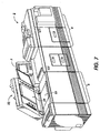
- FIG. 7 there is shown an exemplary electrostatographic printing machine, generally identified by reference numeral 2, the principal operation of which is further described hereinbelow, as well as in various patents cited above and otherwise.
- the printing system 2 is divided into an image input terminal (IIT) 5, a xerographic print engine 6, an electronic controller 7, and a document finishing section 8.
- IIT image input terminal
- xerographic print engine 6 an electronic controller 7
- a document finishing section 8 This printing machine may be represented in a practical embodiment, by any of the well known copier/duplicator products manufactured by Xerox Corporation, such as the model "1075" or "5090", among others.
- the present invention may be incorporated into various other types of printing systems, as for example, ink jet, ionographic, laser-based exposure systems, etc.
- a printing machine of the type shown in Fig. 7 is preferably adapted to provide, in a known manner, duplex or simplex collated copy sets from either duplex or simplex original input documents circulated by a document handler, generally identified by reference numeral 20.
- the image input terminal 5 incorporates an exemplary automatic recirculating document handler (RDH), of a type generally known in the art, for transporting original input documents into position on an imaging platen 23.
- RDH automatic recirculating document handler
- the entire document handler unit 20 may be pivotally mounted on the machine frame so that the recirculating document handler can be pivoted away from the platen 23 by a machine operator for alternative manual document imaging placement and copying and for general access to the imaging platen 23.
- the exemplary printing system 2 is designed to receive input documents which may be manually positioned on the platen glass 23, or automatically transported thereto via a transport belt 24 situated within the document handler 20, generally in contact with the surface of the platen 23 with the document handler 20 pivoted into the position on the platen 23.
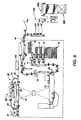
- Fig. 6 illustrates the printing system shown in Fig. 7 in schematic form.
- the RDH 20 operates to automatically feed or transport individual input document sheets onto and over the platen 23 by means of a transport system including transport belt 24.
- Belt 24 may be incrementally driven by a servo motor or various other drive systems known in the art.
- the drive system is typically controlled by a microprocessor controller which may incorporated into electronic control section 7 for sequentially positioning a series of input documents at a desired registration location on the imaging platen 23.
- the RDH 20 is a conventional dual input document handler including both automatic and semiautomatic document handling (SADH) capabilities.
- SADH automatic and semiautomatic document handling
- documents may be fed to the imaging station 23, transported by the platen transport belt 24, from either the SADH input 22 at one side of the RDH 20, or from the regular RDH input, namely the loading or stacking tray 21, on top of the RDH unit.
- document feeding input 22 is referred to herein as the SADH input 22, it will be understood that this input is not limited to semi-automatic or "stream feeding" document input feeding and may be usable for special "job interrupt" insert jobs.
- Automatic RDH document input proceeds by advancing an input document from the bottom of the stack in tray 21 through an arcuate, inverting RDH input path 25 to the upstream end of the platen transport belt 24.
- Input path 25 preferably includes a corrugated feeder-separator belt and air knife system 26, document position sensors (not shown), and a first set of turn baffles and feed rollers for inverting each input document prior to imaging.
- Document inverting or non-inverting by the RDH 20 is further described, for example, U.S. patents 4,794,429 or 4,731,637, among various other patents and publications.
- Each document may be further transported by the platen transport system 24 in the direction of downstream or off-platen rollers where they are fed past a gate or a series of gates and sensors for guiding the sheets directly to a document output path and then to a catch tray, or, more commonly, into an RDH return path 40 for leading the documents back to tray 21 so that the document set can be continually recirculated.
- This RDH return path 40 includes reversible rollers to provide a choice of two different return paths to the RDH tray 21: a simplex return path 44 with one inversion; or a reversible duplex return path 46 without an inversion, whereby the reversible rollers are rotated so as to reverse feed the previous trail edge of the sheet back into the duplex return path 46 from an inverter chute 47.
- This duplex return path 46 provides for the desired inversion of duplex documents in one circulation as they are returned to the tray 21 for copying opposite sides of the input documents in a subsequent circulation or circulations.
- the RDH inverter and inversion path 46, 47 are used only for documents loaded in the RDH input tray 21, and only for duplex documents.
- duplex document In normal operation, a duplex document has only one inversion per circulation, occurring in the RDH input path 24.
- the simplex circulation path requires two inversions per circulation, one in each of the paths 25 and 44, whereby two inversions per circulation is equivalent to no inversion such that simplex documents are returned to tray 21 in their original (face up) orientation via simplex path 44.
- the entire stack of originals in the RDH tray 21 can be recirculated and copied as many times as required to produce a selected plurality of collated copy sets.
- the document set or stack may be RDH recirculated any number of times to produce any desired number of collated duplex print sets, that is, collated sets of duplex copy sheets, in accordance with various instruction sets known as print jobs which can be programmed into the controller 100.
- the fused output copy sheets can be temporarily stacked in a duplex buffer tray 16 if they are to be duplexed, from which they are subsequently inverted and returned, via path 17, for having a second side image transferred thereto in the same manner as the first side.
- This duplex tray 16 has a finite predetermined sheet capacity, depending on the particular copier design.
- the completed duplex copy is preferably transported to an integral finishing and stacking module via output path 18.
- An optionally operated copy path sheet inverter 19 is also provided.
- Output path 18 may be directly connected in a conventional manner to a generally known bin sorter 120 as is generally disclosed in US-A-3,467,371, for example.
- Bin sorter 120 includes a vertical bin array 122 which is conventionally gated to deflect a selected sheet into a selected bin as the sheet is transported past the bin entrance. An optional gated overflow top stacking or purge tray may also be provided for each bin set.
- the vertical bin array 122 may also be bypassed by actuation of a gate therein to direct sheets serially onward.
- finisher 124 may include a stitcher for stapling print sets together and/or a thermal binder for adhesively binding the print sets into books.
- a stacker 125 is also provided for receiving and delivering final print sets to an operator or to an external third party device.
- All copier and document handler and sorter operations are preferably controlled by a generally conventional programmable controller 100 which is typically programmed with certain novel functions and graphic user interface features for the operation of the electrostatographic printing system.
- the controller 100 preferably comprises a known programmable microprocessor system, as exemplified by U.S. Patent No. 4,475,156, as well as extensive prior art, for controlling the operation of the machine and processes described herein, including the actuation of the document and copy sheet feeders, as well as inverters, gates, etc.
- the printer controller monitors and controls all the printer steps and functions as described herein, including imaging onto the photoreceptor, paper delivery, xerographic functions associated with developing and transferring the developed image onto the paper, and collation of sets and delivery of collated sets to the binder or stitcher, as well as to the stacking device.
- the printer controller initiates a sequencing schedule which is highly efficient in monitoring the status of a series of successive print jobs which are to be printed and finished in a consecutive fashion.
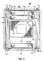
- Fig. 1 shows a transport frame 109 which supports the transport belt 24, illustrated in a broken away view to provide a view of the components concealed thereby.
- the belt 24 is entrained about a drive roller 111 and a tension roller 113 and elongated rollers 114 which are rotatably supported by frame 109 and disposed adjacent document entry and exit points defining a curvilinear path of transport for the belt 24.
- a plurality of elongated slide members or skis 115 extend substantially between the elongated rollers 114 along a linear segment of the curvilinear path of travel of the belt 24, adjacent the imaging platen 23 (not visible in Fig. 1).
- the skis 115 operate to generate load pressure against the belt 24, and in turn, against the input copy document with the document handler in an active position juxtaposed with the imaging platen 23, for urging the input document into a flat configuration thereon.
- the skis 115 may be loaded into an operative position merely by gravity.
- Alternative embodiments have been described in the prior art wherein a spring element or other urging member may be included to provide either a positive or negative load of selected magnitude to the ski 115.
- each ski 115 has upwardly extending mounting fingers 120 extending to a mounting bracket 122 located on frame 109, wherein the fingers 120 are engageable with frame 109 via a grooved portion formed in the finger 120.
- the mounting arrangement preferably permits free movement of the fingers 120 along a longitudinal axis thereof, thereby permitting the skis 115 to move up and down depending on the normal force transmitted from the belt.
- the mounting arrangement also preferably permits slight lateral or rotational movement of fingers 120 for permitting some movement or freedom in the plane parallel to the platen 23.
- the skis 115 are typically provided with upwardly extending portions 131 situated adjacent the input document entry portion of the platen 23.
- each ski 115 can be curled slightly along the tips 133 adjacent the document exit to further reduce wear on the platen 23 at the exit tips 133 of the skis 115.
- various document handlers are present in the marketplace, particularly those having dual directional document feeding capabilities, such that skis having raised or curled tips at both end may be appropriate.
- the ski members 115 are relatively light construction, and may be fabricated from a low weight carbon steel material of between .06 and 1.5 mm and preferably 0.8 mm in thickness. It will be understood that various coatings such as teflon or electrolytic coatings, or a preferred non-electrolytic nickel steel coating can be used to reduce friction between the belt and skis.
- the skis 115 disclosed and taught herein tend to provide a relatively smooth and flat belt surface on which the document to be imaged is maintained so as to urge the input document to be substantially parallel to the platen and in close proximity therewith for eliminating out-of-focus portions in the image produced thereby.
- the skis as thusfar tend induce unacceptable levels of friction which reduces the useful life of the transport belt as well as drive components of the document handler and causes wear of the imaging platen which decreases the quality of the images produced over time.
- the improved ski of the present invention is directed toward an improved ski which is capable of being levitated by the inherent airflow generated by transport motion of the transport belt 24.
- a typical ski as known in the prior art is provided with a particularized configuration for enabling self-levitation thereof. Figs.
- FIG 3-5 illustrate an exemplary embodiment of the present invention, wherein the self-levitating feature thereof is provided a raised air inlet portion 129 situated along the lead edge of the ski 115, in an area corresponding to the document entrance area of the document handling system.
- the air inlet 129 is provided for capturing inherent airflow adjacent the surface of transport belt 24, generated by the transport motion thereof, wherein the captured airflow causes the ski to be slightly elevated, or self-levitated, when the transport belt is in motion. This self-levitation reduces the load pressure produced by the ski when the belt is in motion, thereby reducing frictional forces exerted thereagainst.
- the pressure loading ski operates in a manner similar to the operation of a typical prior art ski with the exception that the ski is slightly elevated during movement of the transport belt 24.
- the ski rests against the belt 24, generating a load pressure thereagainst which is transferred to the input document for causing the document to lay as flat as possible on the imaging platen.
- air in the immediate vicinity of the belt commonly known as the boundary layer, is caused to move, generating airflow in the direction of movement of the belt which is captured by air inlet 129.
- the air pressure underneath the ski is increased to a point at which this air pressure exceeds the air pressure or other forces acting against the top surface of the ski such that the ski is raised in the region of the air inlet by this air pressure differential.
- the air inlet portion 129 of the ski is raised, a greater amount of air is permitted to flow underneath the ski in total, thereby levitating the entire ski.
- the ski is elevated to a height whereby the air volume captured by the inlet is permitted to escape such that the height of levitation becomes a function of the velocity at which the belt is transported.
- the air inlet 129 of ski 115 may be defined by various sizes, shapes and/or configurations sufficient for capturing airflow generated adjacent the surface of transport belt by the movement thereof.
- the self-levitating system may be utilized in a document handling apparatus which employs a single ski or a plurality of skis.
- the self levitating ski of the present invention will not completely eliminate the frictional forces acting against the belt and imaging platen, these frictional forces can be minimized and/or equalized via the instant self-levitating ski.
- the self levitating ski tends to divide the frictional forces into three components: a first component associated with the forces created between the ski and the airflow beneath the ski; and a second component associated with the interface between the airflow and the belt; and a third component associated with belt surface to platen surface contact which tends to be reduced due to the first two component forces.
- a self-levitating pressure loading device for encouraging flat or horizontal orientation of input documents on an imaging platen.
- the self-levitating feature of the present invention reduces the load pressure produced by the ski when the belt is in motion, thereby reducing frictional forces exerted thereagainst to reduce excessive wear and erosion forces.
- the reduced frictional forces substantially reduce the drag and wear associated with prior art document handling systems, yielding a lower cost of operation due to reduced motor torque and operating currents, as well as, increased lifetime of components.
- the present invention also tends to yield increased paper handling reliability.
- an improved document transport for use with document handlers of image input terminals has been disclosed.
Landscapes
- Physics & Mathematics (AREA)
- General Physics & Mathematics (AREA)
- Exposure Or Original Feeding In Electrophotography (AREA)
- Delivering By Means Of Belts And Rollers (AREA)
- Holders For Sensitive Materials And Originals (AREA)
Claims (5)
- Dokumenten-Handhabungssystem zum Zuführen aufeinanderfolgender Eingabedokumente zu einer Bilderzeugungsstation eines Eingabebild-Terminals, aufweisend: ein Transportband (24), das entlang einem vorbestimmten Transportweg für ein reibungsmäßiges Vorschieben individueller Eingabedokumente und für ein sequenzielles Positionieren individueller Eingabedokumente an der Bilderzeugungsstation für eine Bilderzeugung davon angetrieben wird, wobei die Transportbewegung des Transportbands in der Richtung des Transportwegs eine inhärente Luftströmung erzeugt; und
eine Druckaufbringungsvorrichtung (115), die in der Nähe zu dem Transportband (24) liegt, zum Drücken des Transportbands und von Eingabedokumenten in eine im Wesentlichen flache Konfiguration an der Bilderzeugungsstation, dadurch gekennzeichnet, dass
die Druckaufbringungsvorrichtung einen Lufteinlassbereich (129) umfasst, angepasst so, um die inhärente Luftströmung, erzeugt durch die Transportbewegung des Transportbands zum frei Schwebenlassen der Druckaufbringungsvorrichtung (115) zu erfassen. - Dokumenten-Handhabungssystem nach Anspruch 1, wobei das Druckaufbringungselement mindestens ein im Wesentlichen planares, langgestrecktes Kufen-Element (115) umfasst, das das Band (24) über einen ausgedehnten Oberflächenbereich davon berührt.
- Dokumenten-Handhabungssystem nach Anspruch 1 oder Anspruch 2, wobei der Lufteinlassbereich (129) entlang einer Führungskante des Druckaufbringungselements angeordnet ist.
- Dokumentenhandhabungssystem nach einem der vorhergehenden Ansprüche, wobei der Lufteinlassbereich (129) eine nach unten weisende, konkave Form quer zu der Transportbandvorschubrichtung besitzt.
- Elektrostatografische Druckvorrichtung zum Drucken einer Mehrzahl von Druckaufträgen, umfassend ein Dokumenten-Handhabungssystem gemäß einem der vorhergehenden Ansprüche zum Zuführen aufeinanderfolgender Eingabedokumente zu einer Bilderzeugungsstation eines Eingabeblld-Terminals.
Applications Claiming Priority (2)
| Application Number | Priority Date | Filing Date | Title |
|---|---|---|---|
| US841317 | 1992-02-25 | ||
| US08/841,317 US6032952A (en) | 1997-04-30 | 1997-04-30 | Document handling system having a self-levitating pressure loading device |
Publications (2)
| Publication Number | Publication Date |
|---|---|
| EP0875797A1 EP0875797A1 (de) | 1998-11-04 |
| EP0875797B1 true EP0875797B1 (de) | 2003-04-02 |
Family
ID=25284567
Family Applications (1)
| Application Number | Title | Priority Date | Filing Date |
|---|---|---|---|
| EP98302593A Expired - Lifetime EP0875797B1 (de) | 1997-04-30 | 1998-04-02 | Dokumenten-Handhabungssystem mit einer Zuführvorrichtung mit selbst-regulierendem Andruck |
Country Status (5)
| Country | Link |
|---|---|
| US (1) | US6032952A (de) |
| EP (1) | EP0875797B1 (de) |
| JP (1) | JPH1111729A (de) |
| BR (1) | BR9801433A (de) |
| DE (1) | DE69812758T2 (de) |
Families Citing this family (1)
| Publication number | Priority date | Publication date | Assignee | Title |
|---|---|---|---|---|
| CN109153252B (zh) | 2016-08-18 | 2021-05-18 | 惠普发展公司,有限责任合伙企业 | 夹具 |
Family Cites Families (11)
| Publication number | Priority date | Publication date | Assignee | Title |
|---|---|---|---|---|
| LU54091A1 (de) * | 1967-07-12 | 1969-04-29 | ||
| US3988019A (en) * | 1974-05-08 | 1976-10-26 | Windmoller & Holscher | Apparatus for depositing flat articles fed between belts |
| DE2503954A1 (de) * | 1975-01-31 | 1976-08-05 | Agfa Gevaert Ag | Transport- und fuehrungsvorrichtung mit riemenantrieb |
| US3937454A (en) * | 1975-05-16 | 1976-02-10 | Colwill Richard H | Sheet recirculator |
| JPS5528045A (en) * | 1978-08-19 | 1980-02-28 | Ricoh Co Ltd | Sheet-form body feeder |
| US4669721A (en) * | 1986-04-21 | 1987-06-02 | Bell & Howell Company | Sheet transport with bowed guide |
| US4831419A (en) * | 1988-02-12 | 1989-05-16 | Xerox Corporation | Document handler vacuum belt platen transport clamping system |
| US5120046A (en) * | 1991-02-07 | 1992-06-09 | Xerox Corporation | Automatically spaced sheet stacking baffle |
| CA2079349C (en) * | 1991-12-30 | 1997-12-09 | Mark H. Buddendeck | Document handler platen transport |
| DE4242730C2 (de) * | 1992-12-17 | 1997-01-30 | Heidelberger Druckmasch Ag | Bogenausleger einer Druckmaschine |
| DE4433644B4 (de) * | 1994-09-21 | 2005-03-03 | Heidelberger Druckmaschinen Ag | Verfahren und Vorrichtung zur Führung eines Bogens |
-
1997
- 1997-04-30 US US08/841,317 patent/US6032952A/en not_active Expired - Lifetime
-
1998
- 1998-04-02 EP EP98302593A patent/EP0875797B1/de not_active Expired - Lifetime
- 1998-04-02 DE DE69812758T patent/DE69812758T2/de not_active Expired - Fee Related
- 1998-04-23 BR BR9801433A patent/BR9801433A/pt not_active Application Discontinuation
- 1998-04-23 JP JP10113095A patent/JPH1111729A/ja not_active Withdrawn
Also Published As
| Publication number | Publication date |
|---|---|
| JPH1111729A (ja) | 1999-01-19 |
| BR9801433A (pt) | 1999-06-08 |
| DE69812758T2 (de) | 2003-10-16 |
| EP0875797A1 (de) | 1998-11-04 |
| DE69812758D1 (de) | 2003-05-08 |
| US6032952A (en) | 2000-03-07 |
Similar Documents
| Publication | Publication Date | Title |
|---|---|---|
| US5710968A (en) | Bypass transport loop sheet insertion system | |
| US5971387A (en) | Automatic sheet feeder provided in an image forming machine | |
| US5689795A (en) | Sheet transfer apparatus with adaptive speed-up delay | |
| US6286831B1 (en) | Optimized passive gate inverter | |
| JPH0220533B2 (de) | ||
| US8195081B2 (en) | Cut sheet media handling transport | |
| JP2528736B2 (ja) | 画像形成装置 | |
| US5457524A (en) | Dual path sheet feeder | |
| US7149011B2 (en) | Image reading apparatus and image forming apparatus | |
| EP0875797B1 (de) | Dokumenten-Handhabungssystem mit einer Zuführvorrichtung mit selbst-regulierendem Andruck | |
| US6082727A (en) | Top vacuum corrugation feeder with active retard separation mechanism | |
| JP3962539B2 (ja) | 画像形成装置 | |
| JP2506426B2 (ja) | 画像形成装置における用紙押え構造 | |
| US5915689A (en) | Quick change swiper blades | |
| US5608511A (en) | Vacuum transport apparatus | |
| US7063318B2 (en) | Sheet deskew system and method | |
| EP0550233B1 (de) | Plattentransport in einer Dokumentenzuführungseinrichtung | |
| JP4957522B2 (ja) | カール矯正装置、およびカール矯正装置を具備する画像形成装置 | |
| CN101303549A (zh) | 除电装置、介质处理装置以及除电方法 | |
| JP2899211B2 (ja) | シート後処理装置 | |
| MXPA98002519A (en) | Document handling system that has a loading device through autolevitac pressure | |
| JP3316398B2 (ja) | シート給送装置 | |
| JP3791779B2 (ja) | 画像形成装置における排出用紙のカール矯正装置 | |
| JPH05107968A (ja) | 画像形成装置の用紙搬送装置 | |
| JPS6322449A (ja) | シ−ト取扱装置 |
Legal Events
| Date | Code | Title | Description |
|---|---|---|---|
| PUAI | Public reference made under article 153(3) epc to a published international application that has entered the european phase |
Free format text: ORIGINAL CODE: 0009012 |
|
| AK | Designated contracting states |
Kind code of ref document: A1 Designated state(s): DE FR GB |
|
| AX | Request for extension of the european patent |
Free format text: AL;LT;LV;MK;RO;SI |
|
| 17P | Request for examination filed |
Effective date: 19990504 |
|
| AKX | Designation fees paid |
Free format text: DE FR GB |
|
| 17Q | First examination report despatched |
Effective date: 20011017 |
|
| GRAH | Despatch of communication of intention to grant a patent |
Free format text: ORIGINAL CODE: EPIDOS IGRA |
|
| GRAH | Despatch of communication of intention to grant a patent |
Free format text: ORIGINAL CODE: EPIDOS IGRA |
|
| GRAA | (expected) grant |
Free format text: ORIGINAL CODE: 0009210 |
|
| AK | Designated contracting states |
Designated state(s): DE FR GB |
|
| REG | Reference to a national code |
Ref country code: GB Ref legal event code: FG4D |
|
| REF | Corresponds to: |
Ref document number: 69812758 Country of ref document: DE Date of ref document: 20030508 Kind code of ref document: P |
|
| ET | Fr: translation filed | ||
| PLBE | No opposition filed within time limit |
Free format text: ORIGINAL CODE: 0009261 |
|
| STAA | Information on the status of an ep patent application or granted ep patent |
Free format text: STATUS: NO OPPOSITION FILED WITHIN TIME LIMIT |
|
| 26N | No opposition filed |
Effective date: 20040105 |
|
| REG | Reference to a national code |
Ref country code: GB Ref legal event code: 746 Effective date: 20050404 |
|
| PGFP | Annual fee paid to national office [announced via postgrant information from national office to epo] |
Ref country code: GB Payment date: 20070328 Year of fee payment: 10 |
|
| PGFP | Annual fee paid to national office [announced via postgrant information from national office to epo] |
Ref country code: DE Payment date: 20070329 Year of fee payment: 10 |
|
| PGFP | Annual fee paid to national office [announced via postgrant information from national office to epo] |
Ref country code: FR Payment date: 20070411 Year of fee payment: 10 |
|
| GBPC | Gb: european patent ceased through non-payment of renewal fee |
Effective date: 20080402 |
|
| PG25 | Lapsed in a contracting state [announced via postgrant information from national office to epo] |
Ref country code: DE Free format text: LAPSE BECAUSE OF NON-PAYMENT OF DUE FEES Effective date: 20081101 |
|
| REG | Reference to a national code |
Ref country code: FR Ref legal event code: ST Effective date: 20081231 |
|
| PG25 | Lapsed in a contracting state [announced via postgrant information from national office to epo] |
Ref country code: FR Free format text: LAPSE BECAUSE OF NON-PAYMENT OF DUE FEES Effective date: 20080430 |
|
| PG25 | Lapsed in a contracting state [announced via postgrant information from national office to epo] |
Ref country code: GB Free format text: LAPSE BECAUSE OF NON-PAYMENT OF DUE FEES Effective date: 20080402 |