EP0874293A2 - Elektronisches Uhrwerk mit Kalender - Google Patents
Elektronisches Uhrwerk mit Kalender Download PDFInfo
- Publication number
- EP0874293A2 EP0874293A2 EP98303192A EP98303192A EP0874293A2 EP 0874293 A2 EP0874293 A2 EP 0874293A2 EP 98303192 A EP98303192 A EP 98303192A EP 98303192 A EP98303192 A EP 98303192A EP 0874293 A2 EP0874293 A2 EP 0874293A2
- Authority
- EP
- European Patent Office
- Prior art keywords
- date
- ultrasonic
- calendar
- ultrasonic motor
- signal
- Prior art date
- Legal status (The legal status is an assumption and is not a legal conclusion. Google has not performed a legal analysis and makes no representation as to the accuracy of the status listed.)
- Withdrawn
Links
- 230000008602 contraction Effects 0.000 claims description 11
- 235000016496 Panda oleosa Nutrition 0.000 abstract description 11
- 240000000220 Panda oleosa Species 0.000 abstract description 11
- 239000000872 buffer Substances 0.000 description 15
- 238000010586 diagram Methods 0.000 description 10
- 230000010355 oscillation Effects 0.000 description 5
- 239000003990 capacitor Substances 0.000 description 3
- 238000001514 detection method Methods 0.000 description 3
- 230000000694 effects Effects 0.000 description 2
- 230000003203 everyday effect Effects 0.000 description 2
- 230000010287 polarization Effects 0.000 description 2
- 239000000758 substrate Substances 0.000 description 2
- 235000002492 Rungia klossii Nutrition 0.000 description 1
- 244000117054 Rungia klossii Species 0.000 description 1
- 230000015572 biosynthetic process Effects 0.000 description 1
- 238000006073 displacement reaction Methods 0.000 description 1
- 230000005684 electric field Effects 0.000 description 1
- 230000005284 excitation Effects 0.000 description 1
- PCHJSUWPFVWCPO-UHFFFAOYSA-N gold Chemical compound [Au] PCHJSUWPFVWCPO-UHFFFAOYSA-N 0.000 description 1
- 239000010931 gold Substances 0.000 description 1
- 229910052737 gold Inorganic materials 0.000 description 1
- 230000007257 malfunction Effects 0.000 description 1
- 238000004519 manufacturing process Methods 0.000 description 1
- 239000002184 metal Substances 0.000 description 1
- 229910052751 metal Inorganic materials 0.000 description 1
- 238000007747 plating Methods 0.000 description 1
- 238000004904 shortening Methods 0.000 description 1
- 229910001220 stainless steel Inorganic materials 0.000 description 1
- 239000010935 stainless steel Substances 0.000 description 1
- 239000010409 thin film Substances 0.000 description 1
- 238000011282 treatment Methods 0.000 description 1
- 230000010356 wave oscillation Effects 0.000 description 1
Images


Classifications
-
- G—PHYSICS
- G04—HOROLOGY
- G04C—ELECTROMECHANICAL CLOCKS OR WATCHES
- G04C3/00—Electromechanical clocks or watches independent of other time-pieces and in which the movement is maintained by electric means
- G04C3/08—Electromechanical clocks or watches independent of other time-pieces and in which the movement is maintained by electric means wherein movement is regulated by a mechanical oscillator other than a pendulum or balance, e.g. by a tuning fork, e.g. electrostatically
- G04C3/12—Electromechanical clocks or watches independent of other time-pieces and in which the movement is maintained by electric means wherein movement is regulated by a mechanical oscillator other than a pendulum or balance, e.g. by a tuning fork, e.g. electrostatically driven by piezoelectric means; driven by magneto-strictive means
-
- G—PHYSICS
- G04—HOROLOGY
- G04C—ELECTROMECHANICAL CLOCKS OR WATCHES
- G04C17/00—Indicating the time optically by electric means
- G04C17/005—Indicating the time optically by electric means by discs
- G04C17/0058—Indicating the time optically by electric means by discs with date indication
- G04C17/0066—Indicating the time optically by electric means by discs with date indication electromagnetically driven, e.g. intermittently
Definitions
- the present invention relates to calendar electronic timepieces that are capable of indicating a date, and more particularly to a calendar electronic timepiece that can rotate a date dial with high torque by using an ultrasonic motor and accurately position a date character of the date dial in position.
- a battery 902 constitutes a power source, for example, as shown in Fig. 21.
- An IC 904 is connected to the battery 902 to count time information about a time and date, etc.
- a timepiece motor 906 rotates, for example, by 180 degrees per second based on a time information signal outputted by the IC 904.
- a multistage reduction wheel train 908 is formed by a plurality of gears. The multistage reduction wheel train 908 reduces and transmits the speed of the timepiece motor 906 to rotate a hand driving wheel 910. Time information, e.g. "hour”, "minute” and "second”, is indicated by the hand driving wheel 910 formed respectively by an hour pointer, a minute pointer and a second pointer.
- a date dial 912 is intermittently operated by the multistage reduction wheel train 908 to indicate a "date” by a character of from “1" to "31” provided on indicating surfaces of the date dial 912.
- a battery 902 constitutes a power source, for example, as shown in Fig. 22.
- An IC 904 is connected to the battery 902 to count time information about a time and date, etc.
- a timepiece motor 906 rotates, for example, by 180 degrees per second based on a time information signal outputted by the IC 904.
- a reduction wheel train (not shown) is formed reduces and transmits the speed of the timepiece motor 906 to rotate a hand driving wheel 910.
- Time information e.g. "hour”, "minute” and "second” is indicated by the hand driving wheel 910 formed respectively by an hour pointer, a minute pointer and a second pointer.
- a date dial motor 914 is rotated based on date information signal outputted by the IC 904.
- An multistage reduction wheel train 916 reduces and transmits the speed of a date dial motor to rotate a date dial 912.
- a "date” is indicated by a character of from “1” to "31” provided on indicating surfaces of the date dial 912.
- a date dial motor 914 includes a coil block 918 for the date dial motor, a date dial stator 920, and a date dial stator 922, as shown in Fig. 23 and Fig. 24.
- a multi-stage reduction wheel train 916 includes a first transmitting wheel 924, a second transmitting wheel 926, and a date driving wheel 928.
- the date driving wheel 928 is in mesh with a tooth portion 912a of a date dial. Numerals of from “1" to "31" are provided on indicating surfaces 912b of the date dial.
- An IC 904 counts time information about a time and date, etc.
- the date dial motor 914 rotates based on the time information signal outputted by the IC 904. This turns, through the first transmitting wheel 924, the second transmitting wheel 926 and the date dial wheel 928, the date dial 912 by 360°/31, i.e. a 1/31 rotation.
- an analog-type electronic timepiece using an ultrasonic motor as a timepiece motor 906 time is indicated by an hour pointer, a minute pointer, and a second pointer through a wheel train driven by a moving body of the ultrasonic motor.
- time is indicated by an hour pointer, a minute pointer, and a second pointer through a wheel train driven by a moving body of the ultrasonic motor.
- an electronic appliance using a conventional ultrasonic motor there is provided a vibrating member joined with a piezoelectric element so that the moving body is frictionally driven by vibrating waves generated in the vibrating member due to expansion and contraction of the piezoelectric element.
- a pressure applying means causes the moving body to be pressure-contacted with the vibrating member.
- An oscillation driving circuit applies a drive signal to an electrode group formed in the piezoelectric element. This drive signal causes the piezoelectric element to expand, generating vibrating waves on the vibrating member. The vibrating waves cause the moving body to be frictionally driven.
- the structure of an electronic appliance using the conventional ultrasonic motor is disclosed, e.g. in Japanese Laying-open Patent Publication No. H8-251952.
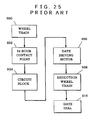
- a wheel train is provided, at a part thereof, with a 24-hour contact 932 for detecting a rotational position of the wheel train 930, as shown in Fig. 25.
- the 24-hour contact 932 detects a position corresponding to 0 o'clock a.m.
- the 24-hour contact 932 outputs a detection signal by which a circuit block 934 causes the date driving motor 936 to rotate.
- the rotation of the date driving motor 936 rotates the date dial 912 through a reduction wheel train 938. This makes possible change of date indication.
- a circuit block (CPUIC) 940 counts time, as shown in Fig. 26.
- the date driving motor 936 is rotated.
- the rotation of the date driving motor 936 causes the date dial 912 to rotate through rotation of the reduction wheel train 938. This makes possible change of date indication.
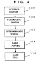
- the present invention is structured by, in a calendar electronic timepiece, having a function to indicate information about calendar, the calendar electronic timepiece being characterized by comprising: a control circuit having a calendar signal generating circuit for counting on information about calendar such as year, month and day to generate a calendar signal, and an ultrasonic motor driving circuit for outputting an ultrasonic motor driving signal to rotate an ultrasonic motor based on the calendar signal outputted by the calendar signal generating circuit; an ultrasonic motor having an ultrasonic stator joined with a piezoelectric element, and an ultrasonic rotor inputted by the ultrasonic motor driving signal to be frictionally driven by vibrating waves generated on the ultrasonic stator due to expansion and contraction of the piezoelectric element; a calendar indicating wheel operated based on rotation of the ultrasonic rotor to indicate information about calendar.
- a calendar electronic timepiece of the present invention is preferably structured such that the calendar indicating wheel is a date dial for indicating information about days, the calendar signal generating circuit counting on information about a leap year and a day of from January to December, the ultrasonic motor driving circuit outputting a different ultrasonic motor drive signal from that for changing from an end of a large month to a succeeding month based on a count result of the calendar signal generating circuit when changing from an end of a small month to a succeeding month so that a day indication of 1 is made on a 1st day of each month.
- a calendar electronic timepiece of the present invention is preferably structured such that a calendar wheel train is provided to operate based on the rotation of the ultrasonic rotor, the calendar indicating wheel being operated by the calendar wheel train.
- a calendar electronic timepiece of the present invention is preferably structured such that a finger is provided to operate based on the rotation of the ultrasonic rotor, the calendar indicating wheel being rotated by the finger.
- a calendar electronic timepiece of the present invention is preferably structured such that a rectifying member is provided to rectifying a position along a rotational direction of the calendar indicating wheel.
- the present invention is structured by, in a calendar electronic timepiece, having a function to indicate information about calendar, the calendar electronic timepiece being characterized by comprising: a time signal generating circuit for counting on information about date to generate a date signal; an ultrasonic motor driving circuit for outputting an ultrasonic motor driving signal to drive an ultrasonic motor based on the date signal outputted by the time signal generating circuit; an ultrasonic motor having an ultrasonic stator joined with a piezoelectric element, and an ultrasonic rotor inputted by the ultrasonic motor driving signal to be frictionally driven by vibrating waves generated on the ultrasonic stator due to expansion and contraction of the piezoelectric element; a calendar wheel train rotated by rotation of the ultrasonic rotor; a date finger rotated by rotation of the calendar wheel train; a date dial rotated by rotation of the date finger to indicate a date.
- the date dial is stabilized in rotational characteristics because high torque can be produced and the calendar wheel train is driven by the ultrasonic motor.
- the present invention is structured by, in a calendar electronic timepiece, having a function to indicate information about calendar, the calendar electronic timepiece being characterized by comprising: a time signal generating circuit for counting on information about date to generate a date signal; an ultrasonic motor driving circuit for outputting an ultrasonic motor driving signal to drive an ultrasonic motor based on the date signal outputted by the time signal generating circuit; an ultrasonic motor having an ultrasonic stator joined with a piezoelectric element, and an ultrasonic rotor inputted by the ultrasonic motor driving signal to be frictionally driven by vibrating waves generated on the ultrasonic stator due to expansion and contraction of the piezoelectric element; a calendar wheel train rotated by rotation of the ultrasonic rotor and having a date finger; a date dial rotated by rotation of the date finger to indicate a date.
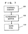
- the present invention is structured by, in a calendar electronic timepiece, having a function to indicate information about calendar, the calendar electronic timepiece being characterized by comprising: a time signal generating circuit for counting on information about date to generate a date signal; an ultrasonic motor driving circuit for outputting an ultrasonic motor driving signal to drive an ultrasonic motor based on the date signal outputted by the time signal generating circuit; an ultrasonic motor having an ultrasonic stator joined with a piezoelectric element, and an ultrasonic rotor inputted by the ultrasonic motor driving signal to be frictionally driven by vibrating waves generated on the ultrasonic stator due to expansion and contraction of the piezoelectric element and having a date finger; a date dial rotated by rotation of the date finger provided on the ultrasonic rotor to indicate a date.
- the present invention is structured by, in a calendar electronic timepiece, having a function to indicate information about calendar, the calendar electronic timepiece being characterized by comprising: a time signal generating circuit for counting on information about date to generate a date signal; an ultrasonic motor driving circuit for outputting an ultrasonic motor driving signal to drive an ultrasonic motor based on the date signal outputted by the time signal generating circuit; an ultrasonic motor having an ultrasonic stator joined with a piezoelectric element, and an ultrasonic rotor constituting a date dial inputted by the ultrasonic motor driving signal to be frictionally driven by vibrating waves generated on the ultrasonic stator due to expansion and contraction of the piezoelectric element.
- a calendar electronic timepiece of the present invention is preferably structured such that a date jumper is provided in engagement with a tooth portion of the date dial to rectify a rotational position of the date dial.
- an ultrasonic motor as a first embodiment of a calendar electronic timepiece 100 of the present invention includes an ultrasonic rotor 102.
- the ultrasonic rotor 102 has an ultrasonic rotor kana 192b in mesh with an intermediate date driving gear 104a of an intermediate date driving wheel 104.
- the intermediate date driving wheel 104 has an intermediate date driving kana in mesh with a date driving gear 106a of a date driving wheel 106.
- a date finger 18 is provided on the date driving wheel 106 so as to be simultaneously rotated by the rotation of the date driving wheel 106.
- the date finger 108 may be provided two, or the date finger 108 may be provided one or three or more.
- a date dial 110 having 31 date wheel teeth 110a is rotatably assembled on a main plate 112.
- the date dial 110 has numerals "1" to "31” (not shown) on indicating surfaces 110c.
- a battery 114 is attached onto an opposite side of the main plate 112 to the side having the date dial 110.
- a date jumper 116 is integrally formed with a date dial holder 118.
- the date jumper 116 has a rectifying portion 116a for rectifying the date dial teeth 110a.
- the date jumper 116 has a date jumper spring portion 116b.
- an ultrasonic rotor axle 120 is fixed to a main plate 112.
- the ultrasonic rotor axle 120 has an ultrasonic stator 122 fixed thereon.
- the ultrasonic stator 122 has a piezoelectric element (not shown) firmly fixed thereon.
- a ultrasonic rotor 102 is rotatably assembled on the ultrasonic rotor axle 120, and contacted with a displacement-magnifying comb teeth 122c of the ultrasonic stator 122.
- An ultrasonic spring 124 urges the ultrasonic rotor 102 so as to apply an elastic force to the displacement-magnifying comb teeth 122c.
- An intermediate date driving wheel 104 is assembled between the main plate 112 and the date dial holder 118.
- the ultrasonic rotor 102 has an ultrasonic rotor kana 102b in mesh with intermediate date driving gear 104b of the intermediate date driving wheel 104.
- a date driving wheel 106 is rotatably assembled on the main plate 112.
- the intermediate date driving wheel 104 has a intermediate date driving kana 104b in mesh with the date driving gear 106a of the date driving wheel 106.
- the date drive wheel 106 has a date finger 106 provided thereon so as to be rotated by the date wheel 106 simultaneously therewith.
- a date dial having 31 date teeth 110a is rotatably assembled on the main plate 112.
- the date dial 110 has numerals "1" to "31” on indicating surfaces 110c thereof.
- a control circuit 130 has a time signal generating circuit for counting information on time and date to generate a date signal, and further an ultrasonic motor driving circuit for outputting an ultrasonic motor driving signal to drive an ultrasonic motor (USM) based on the date signal outputted by the time signal generating circuit.
- USM ultrasonic motor
- the ultrasonic stator 122 constituting a vibrating member of the ultrasonic motor, is bonded with, on one surface, a piezoelectric element 802 formed with two sets of electrode groups 803a, 803b having a plurality of electrodes.
- An oscillation drive circuit 825 is connected to the electrode groups 803a, 803b of the piezoelectric element 802.
- An inverter 812 serves as an inverting power amplifier for amplifying an electric signal as excitation information from electrodes 803c formed on one surface formed with the electrode groups 803a, 803b and the other end or the ultrasonic stator 122.
- a resistor 813 is connected in parallel with the inverter 812 to stabilize for an operating point of the inverter 812.
- the inverter 812 has an output terminal connected to input terminals of two sets of buffers 811a, 811b. Each of the output terminals of the two buffers 811a, 811b is connected to the electrode group 803a, 803b.
- a capacitor 815 has one end connected to the input terminal of the inverter 812, while a capacitor 816 has one end connected through a resistor 814 to the output terminal of the inverter 812. The capacitors 815, 816 have the other end being grounded to perform phase adjustment within the oscillation drive circuit 825.
- the inverter 812 and the buffers 811a, 811b respectively has, at input terminals and output terminals, control terminals so that they are an inverter and a buffer of a tri-state structure that is capable of bringing the output terminal into a high impedance state depending upon the inputting signal to the control terminal.
- a forward/reverse signal generating means 820 outputs a forward/reverse signal for setting a rotational direction of the ultrasonic motor to a switching circuit 826.
- the switching circuit has output terminals respectively connected to the control terminals of the tri-state buffers 811a, 811b and the tri-state inverter 812 of the oscillation drive circuit 825, so as to cause one of the tri-state buffers 811a, 811b to function as a usual buffer and the other buffer at its output terminal to be in a high impedance state for being disabled.
- the ultrasonic stator 122 is driven by the tri-state buffer that functions as a usual buffer that is selected by the output signal of the switching circuit 826.
- the ultrasonic stator 122 is driven only by the tri-state buffer that is allowed to function as a usual buffer by the switching circuit 826.
- the tri-sate buffer allowed to function as a usual buffer is changed over by the switching circuit 826, the ultrasonic motor is reversed of rotational direction.
- the tri-state inverter can be placed at its output terminal in the high impedance state by the output signal of the switching circuit 826 that is outputted based on the output of the forward/reverse signal generating means 820.
- the tri-state buffers 811a, 811b are both disabled so that the ultrasonic motor can be stopped.
- a disc-shaped ultrasonic stator 122 has a disc-shaped piezoelectric element 802 joined to a flat surface thereof by adhesion or thin-film formation, or the like.
- the ultrasonic motor causes standing wave oscillation with two wavelengths in a circumferential direction of the ultrasonic stator 122, rotatably driving the ultrasonic rotor.
- the piezoelectric element 802 is formed, at one flat surface, with eight-segmented electrodes having four times the number of waves in the circumferential direction, to provide an alternate arrangement with a first electrode group 803a and a second electrode group 803b through polarization-treating to (+) and (-), as shown in Fig. 28 and Fig. 29.
- the first electrode group 803a is structured by electrodes a1, a2, a3, a4, each of which electrodes is short circuited by a connection means 814a.
- the second electrode group 803a is structured by electrodes b1, b2, b3, b4, each of which electrodes is short circuited by a connection means 814b.
- (+) and (-) denotes directions of polarization treatments, which are respectively treated of polarization by applying positive and negative electric fields through a joint surface side of the piezoelectric elements to the ultrasonic stator 122.
- the ultrasonic stator 122 is provided, at a surface thereof and around boundaries of the electrodes, with projections (comb teeth) 817 for magnifying the displacement of the ultrasonic stator and transmitting a drive force from the ultrasonic stator to the ultrasonic rotor.
- the ultrasonic stator 122 is driven by applying a radio frequency voltage generated by the oscillation drive circuit 825 to either one of the electrode groups 803a or 803b.
- the rotational direction of the ultrasonic motor can be switched over depending upon which electrode group the ultrasonic stator 122 is driven with.
- the ultrasonic motor used for the calendar electronic timepiece of the present invention is driven by the above structure formed by the drive circuit, the piezoelectric element and the ultrasonic stator. However, it is possible to drive it by other structures.
- the control circuit 130 when outputting a count result of zero o'clock a.m., outputs an ultrasonic motor drive signal to the ultrasonic motor (USM) 132. That is, the control circuit 130 is structured so as to output an ultrasonic motor drive signal for rotating the date dial 110 by 360°/31, i.e. a 1/31 rotation, once a day.
- the control circuit 130 counts for "year”, “month”, “day” and hour.
- the control circuit 130 outputs a count result of zero o'clock a.m. for a usual day, it outputs an ultrasonic motor drive signal corresponding to the usual day to the ultrasonic motor (USM) 132. That is, the control circuit 130 is structured so as to output an ultrasonic motor drive signal for rotating the date dial 110 by 360°/31, i.e. a 1/31 rotation, once a day.
- the control circuit 130 when the control circuit 130 outputs a count result of zero o'clock a.m. of March 1 of a year not falling on a leap year, e.g. March 1 of 1997, the control circuit 130 outputs an ultrasonic motor drive signal corresponding to March 1 to the ultrasonic motor (USM) 132. That is, the control circuit 130 is structured so as to output an ultrasonic motor drive signal for rotating the date dial 110 by (360°/31) ⁇ 4, i.e. a 4/31 rotation. Therefore, the information on the "day” indicated by the date dial 110 is changed from an indication "28" corresponding to February 28 to an indication "1" corresponding to March 1, without indicating "29", "30” and "31".
- the control circuit 130 when the control circuit 130 outputs a count result of zero o'clock a.m. of March 1 of a leap year, e.g. March 1 of 2000, the control circuit 130 outputs an ultrasonic motor drive signal corresponding to March 1 of the leap year to the ultrasonic motor (USM) 132. That is, the control circuit 130 is structured so as to output an ultrasonic motor drive signal for rotating the date dial 110 by (360°/31) ⁇ 3, i.e. a 3/31 rotation. Therefore, the information on the "day” indicated by the date dial 110 is changed from an indication "29" corresponding to February 29 to an indication "1" corresponding to March 1, without indicating "30" and "31".
- the control circuit 130 when the control circuit 130 outputs a count result of a next day, i.e. "30th" to a last day of a "small" month, e.g. 0 o'clock a.m. of May 1st, the control circuit 130 outputs an ultrasonic motor drive signal corresponding to May 1st to the ultrasonic motor (USM) 132. That is, the control circuit 130 is structured to output an ultrasonic motor drive circuit for rotating the date dial 110 by (360°/31) ⁇ 2, i.e. a 2/3 rotation. Consequently, the information about the "day” indicated by the date dial 110 is changed from an indication "30" for April 30th to an indication "1" for May 1st, without indicating "31".
- the calendar electronic timepiece constitutes a "auto-calendar timepiece” or a “perpetual calendar timepiece”.
- the ultrasonic motor (USM) 132 has an ultrasonic stator joined with a piezoelectric element and an ultrasonic rotor frictionally driven by vibratory waves generated in the ultrasonic stator due to inputting of an ultrasonic motor drive signal for expanding and shrinking the piezoelectric element.
- the piezoelectric element is formed, at a surface, at least two sets of electrode groups formed by a plurality of electrodes.
- the control circuit 130 has at least two power amplifiers. These power amplifiers has output terminals respectively connected to two sets of electrode groups to independently drive the electrode.
- the ultrasonic rotor of the ultrasonic motor (USM) 132 is rotated upon inputting an ultrasonic motor drive signal to the electrode group of the piezoelectric element.
- the rotation of the ultrasonic rotor causes rotation of the intermediate wheel, i.e. the intermediate date drive wheel 104.
- the rotation of the intermediate date drive wheel rotates the date finger 108, and the date finger 108 causes the date dial 110 to rotate.
- the calendar electronic timepiece of the present invention may have a calendar indicating wheel for indicating other calendar information, e.g. "year”, “month”, “day of the week”, “six day of the week”, etc.
- a day indicator for indicating "day of the week"
- a day indicator having 28 day indicator teeth (not shown) is rotatably assembled on a main plate 112.
- the control circuit 130 has a time signal generating circuit for counting information on time of the day and day of the week to generate a day-of-the-week signal, and further an ultrasonic motor drive circuit for outputting an ultrasonic motor drive signal for rotating the ultrasonic motor based on the day-of-the-week signal outputted by the time signal generating circuit.
- the control circuit 130 when outputting a count result of zero o'clock a.m., outputs an ultrasonic motor drive signal to the ultrasonic motor (USM) 132. That is, the control circuit 130 is structured to output an ultrasonic motor drive signal to rotate the day indicator by 360°/14, i.e. a 1/14 rotation, once a day.
- the day of the week can be indicated in Japanese or English, as required, by the day indicator.
- a month dial (not shown) having 36 month-wheel teeth (not shown) is rotatably assembled on a main plate 112.
- the numerals of from “1” to “12” are provided in three sets in order on indicating surfaces of the month dial. That is the month dial is provided with totally 36 numerals, such as 1 - 12, 1 - 12, 1 - 12, on the indicating surfaces thereof.
- the control circuit 130 has a time signal generating circuit for counting information on time of the day and month to generate a month signal, and further an ultrasonic motor drive circuit for outputting an ultrasonic motor drive signal for rotating the ultrasonic motor based on the month signal outputted by the time signal generating circuit.
- the control circuit 130 when outputting a count result of 1st day of the month, outputs an ultrasonic motor drive signal to the ultrasonic motor (USM) 132. That is, the control circuit 130 is structured to output an ultrasonic motor drive signal to rotate the month indicator by 360°/36, i.e. 1/36 rotation, on every 1st day of the month.
- the month can be indicated by the month indicator.
- an ultrasonic motor of a second embodiment of a calendar electronic timepiece 200 of the present invention is similar to the ultrasonic motor of the first embodiment of the calendar electronic timepiece 200 of the present invention shown in Fig. 3.
- a date driving wheel 106 is rotatably assembled on a main plate 112.
- a ultrasonic rotor 102 has an ultrasonic rotor kana 102b is in mesh with date driving gear 106a of the date driving wheel 106a.
- a date finger 108 is provided on the date driving wheel 106 so as to be simultaneously rotated by the rotation of the date driving wheel 106.
- a date dial 110 having 31 of date dial teeth 110a is assembled on the main plate 112. Numerals of from “1" to “31” (not shown) are provided on indicating surfaces 110c of the date dial 110.
- the calendar electronic timepiece 200 is provided with a date jumper (not shown).
- the date jumper has a rectifying portion for rectifying the date dial teeth 110a.
- the control circuit 130 has a time signal generating circuit for counting information on time of the day and date to generate a date signal, and further an ultrasonic motor drive circuit for outputting an ultrasonic motor drive signal for rotating the ultrasonic motor based on the date signal outputted by the time signal generating circuit.
- the control circuit 130 when outputting a count result of zero o'clock a.m., outputs an ultrasonic motor drive signal to the ultrasonic motor (USM) 132. That is, the control circuit 130 is structured to output an ultrasonic motor drive signal to rotate the date dial by 360°/31, i.e. 1/31 rotation, once a day.
- the ultrasonic motor (USM) 132 has an ultrasonic rotor that is rotated by inputting an ultrasonic motor drive signal to the electrode group of the piezoelectric element. The rotation of the ultrasonic rotor rotates the date finger 108 so that the date finger 108 caused the date dial 110 to rotate.
- an ultrasonic motor of a third embodiment of a calendar electronic timepiece 300 of the present invention is similar to the ultrasonic motor (USM) 132 of the first embodiment of the calendar electronic timepiece 200 of the present invention shown in Fig. 3.
- a date dial 110 is rotatably assembled on a main plate 112.
- a ultrasonic rotor 102 has an ultrasonic rotor kana 102b is in mesh with date dial teeth 110a of the date driving wheel 106a.
- Numerals of from “1" to "31” are provided on indicating surfaces 110c of the date dial 110.
- the calendar electronic timepiece 300 is provided with a date jumper (not shown).
- the date jumper has a rectifying portion for rectifying the date dial teeth 110a.
- the control circuit 130 has a time signal generating circuit for counting information on time of the day and date to generate a date signal, and further an ultrasonic motor drive circuit for outputting an ultrasonic motor drive signal for rotating the ultrasonic motor based on the date signal outputted by the time signal generating circuit.
- the control circuit 130 when outputting a count result of zero o'clock a.m., outputs an ultrasonic motor drive signal to the ultrasonic motor (USM) 132. That is, the control circuit 130 is structured to output an ultrasonic motor drive signal to rotate the date dial by 360°/31, i.e. a 1/31 rotation, once a day.
- the ultrasonic motor (USM) 132 has an ultrasonic rotor that is rotated by inputting an ultrasonic motor drive signal to the electrode group of the piezoelectric element. The rotation of the ultrasonic rotor rotates the date finger 108 so that the date finger 108 caused the date dial 110 to rotate.
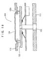
- a calendar electronic timepiece 400 of the present invention has an ultrasonic rotor axle 120 fixed on the main plate 112.
- An ultrasonic stator (USM) stator 122 is fixed on the rotor axle 120.
- a piezoelectric element (not shown) is firmly fixed to the ultrasonic stator 122.
- a date dial 110 contacts with displacement-magnifying comb teeth 122c of the ultrasonic stator 122. That is, the date dial 110 constitutes the ultrasonic rotor 102.
- a ultrasonic spring 124 urges the date dial 110 in a manner applying an elastic force to the displacement-magnifying comb teeth.
- a calendar electronic timepiece 400 is provided with a date jumper (not shown).
- the date jumper has a rectifying portion to rectify the dial teeth 110a.
- the control circuit 130 has a time signal generating circuit for counting information on time of the day and date to generate a date signal, and further an ultrasonic motor drive circuit for outputting an ultrasonic motor drive signal for rotating the ultrasonic motor based on the date signal outputted by the time signal generating circuit.
- the control circuit 130 when outputting a count result of zero o'clock a.m., outputs an ultrasonic motor drive signal to the ultrasonic motor (USM) 132. That is, the control circuit 130 is structured to output an ultrasonic motor drive signal to rotate the date dial 110 by 360°/31, i.e. a 1/31 rotation, once a day.
- the ultrasonic motor (USM) has the ultrasonic stator 122 joined with a piezoelectric element.
- the date dial 110 is frictionally driven by vibratory waves generated on the ultrasonic stator due to expansion of the piezoelectric element when the piezoelectric signal is inputted with an ultrasonic motor drive signal.
- a fifth embodiment of a calendar electronic timepiece 500 has a wheel train having, at a part thereof, a 24h contact 532 for detecting a rotational position of the wheel train 530.
- a 24-hour wheel 550 has a 24-o'clock contact point spring 552.
- the 24-hour contact point spring 552 has two 24-o'clock contact point spring terminals 552a and 552b.
- a circuit block 534 is provided with a pattern for the 24-o'clock contact point spring terminals (not shown) that is formed corresponding to a portion of a circumferential portion. along a path of rotation of tips of the 24-hour contact point spring terminals 552a and 552b.
- the 24-o'clock contact point spring 552 is arranged contactable with the 24-o'clock contact point spring terminal pattern (not shown) of the circuit block 534.
- the 24-hour wheel 550 is in mesh with a hour wheel 554, and rotated one per day.
- the hour wheel 554 makes one rotation per 12 hours to indicate an "hour” by a hour hand (not shown) attached to the hour wheel.
- a date driving wheel 106 is rotatably assembled on the main plate 112.
- the date driving wheel 106 constitute a date driving reduction wheel train 560.
- the ultrasonic rotor 102 of the ultrasonic motor 132 has a ultrasonic rotor kana 102b in mesh with a date driving gear 106 of the date driving wheel 106.
- the ultrasonic motor including the ultrasonic rotor 102 constitutes a date driving motor 562.
- a date finger 108 is provided on the date driving wheel 106 so that it is simultaneously rotated by rotation of the date driving wheel 106.
- a date dial 110 having 31 of date dial teeth 110a is rotatably assembled on the main plate 112. Numerals of from “1" to “31” (not shown) are provided on surfaces 110c of the date dial 110.
- a date dial holder 118 rotatably holds the date dial 110.
- the calendar electronic timepiece 500 is provided with a date jumper 116.
- the date jumper 116 has a rectifying portion 116a to rectify the date dial teeth 110a.
- the date driving wheel 106 has a date driving wheel contact point spring 556.
- the date driving wheel contact point spring 556 has two date driving wheel contact point spring terminals 556a and 556b.
- a circuit block 534 is provided with a pattern for the date driving wheel contact point spring terminals (not shown) that is formed corresponding to a portion of a circumferential portion along a path of rotation of tips of the date driving wheel contact point spring terminals 556a and 556b.
- the date driving wheel contact point spring 556 is arranged contactable with the date driving wheel contact point spring terminal pattern (not shown) of the circuit block 534.
- the date driving wheel contact point spring 556 constitutes a date driving contact 564.
- a transmitting wheel 620 is rotatably assembled in the electronic timepiece.
- the transmitting wheel is a part included in a train such as the wheel train or calendar wheel train for the calendar electronic timepiece.
- the transmitting wheel 620, in the calendar electronic timepiece 500 of the present invention, corresponds to the 24-hour wheel 550 and the date driving wheel 106.
- a contact point spring 622 is fixed on the transmitting wheel 620.
- the contact point spring 622 is structured to have an electric conductivity.
- the contact point spring 622 may be formed of a metal such as a stainless steel, or having a gold plating on a surface thereof.
- a terminal contact portion 622c is provided at a tip of the contact point spring terminal 622a, while a terminal contact portion 622d is provided at a tip of the contact point spring terminal 622a.
- a circuit substrate 624 is assembled in the calendar electronic timepiece, and has an A pattern 626 and a B pattern 628 provided on a surface of the circuit substrate 624.
- the A pattern 626 and the B pattern 628 are connected to the control circuit (not shown).
- a rotational position detecting signal is inputted to the control circuit (not shown).
- the contact point spring 622 extends almost in a straight line form through a rotational center 630 of the transmitting wheel 620.
- the A pattern A and the B pattern 628 are arranged at almost 180 degrees relative to the rotational center 630 of the transmitting wheel 620. Consequently, when the transmitting wheel 620 rotates, a state occurs that the terminal contact portion 622c is contacted with the A pattern 626 and the terminal contact portion 622d is contacted with the B pattern 628. At this time, a position detecting signal is inputted to a control circuit (not shown). When the transmitting wheel 620 further rotates, the terminal contact portion 622c becomes out of contact from the A pattern 626 and the terminal contact portion 622d out of the contact from the B pattern 628. At this time, no rotational position detecting signal is generated.
- the terminal contact portion 622c becomes contact with the B pattern 628 and the terminal contact portion 622d contact with the A pattern 626.
- a rotational position detecting signal is again inputted to the control circuit (not shown).
- the terminal contact portion 622c is detached from the B pattern 628 and the terminal contact portion 622d is detached from the A pattern 626.
- no rotational position detecting signal is generated.
- the contact portions similarly operate regardless whether the transmitting wheel 620 rotates in a clockwise direction or rotates in a counterclockwise direction.
- the rotational direction detecting signal is twice inputted to the control circuit (not shown) . Consequently, where the transmitting wheel is structured to perform one rotation per 24 hours, the rotational position detecting signal is inputted to the control circuit (not shown) every 12 hours. Where there is a necessity of counting by 24 hours as in a case of changing date indication, a provision is made such that a counting circuit for counting the number of generations of the rotational position detecting signals is provided in the control circuit so that a signal for changing the date indication is outputted when the rotational position detecting signal is twice inputted.
- the 24-hour contact point spring 552 contacts with the first pattern (not shown) of the circuit block 534.
- the 24-hour contact point spring outputs a detection signal by which the circuit block 534 causes the ultrasonic rotor 102 of the ultrasonic motor 132 to rotate.
- the rotation of the ultrasonic rotor 102 rotates the date driving wheel 106 to rotate the date dial 110 through the date finger 108. This makes possible change of date indication.
- the date driving wheel contact point spring 556 comes into contact with the second pattern (not shown) of the circuit block 534. At this time, the date driving wheel contact point spring 556 outputs a detection signal by which the circuit block 534 stops rotation of the ultrasonic rotor 102 of the ultrasonic motor 132.
- the time of starting and ending the date drive is not necessarily accurately at 0 o'clock a.m. It may be a time before 0 o'clock a.m. or after 0 o'clock a.m.
- the calendar electronic timepiece of the present invention has preferably the following structures.
- Fig. 14 shows a main surface side portion of a movement (mechanical members) of the first embodiment of the calendar electronic timepiece of the present invention.
- the "main surface side portion” refers to a portion opposite to the side having the dial 570 with respect to the main plate.
- Fig. 15 shows a back surface side portion of the movement (mechanical members) of the first embodiment of the calendar electronic timepiece of the present invention.
- the "back surface side portion” refers to a portion on the side having the dial 570 with respect to the main plate. That is, the date dial is assembled on the "back surface side”.
- a calendar electronic timepiece shown in Fig. 14 to Fig. 20 has also a contact point spring as possessed by the fifth embodiment of the present invention.
- the calendar electronic timepiece of the present invention has a main plate 112.
- a step motor 610 has a rotor 612 in mesh with a fifth wheel 614, and the fifth wheel 614 is in mesh with a fourth wheel 616.
- the rotation of the fourth wheel 616 rotates, through a third wheel 618, a minute wheel 620, which further rotates, through a date back wheel 622, an hour wheel 554.
- a 24-hour wheel 550 has a 24-hour contact point spring 552.
- the 24-hour contact point spring 552 is arranged contactable with a first pattern (not shown) of a circuit block 534.
- the 24-hour wheel 550 is in mesh with the hour wheel 554 and rotated by one rotation per day.
- the hour wheel rotates by one turn per 12 hours so as to indicate an "hour” by an hour pointer (not shown) mounted on the hour wheel 554.
- An ultrasonic motor 132 has an ultrasonic rotor axle 120 fixed on the main late 112 so that an ultrasonic rotor 102 is rotatably assembled on the ultrasonic rotor axle 120.
- the ultrasonic rotor 102 has an ultrasonic rotor kana 102b in mesh with an intermediate date driving gear 104a.
- the intermediate date driving wheel 104 has an intermediate date driving kana 104b in mesh with a date driving gear 106a of the date driving wheel 106.
- a date finger 108 is provided on the date driving wheel 106.
- a date dial 110 that is simultaneously rotated by the rotation of the date driving wheel 106, is rotatably assembled on the main plate 112.
- a battery 114 is assembled on an opposite side to the side mounted with the date dial 110 with respect to the main plate 112.
- a ate jumper 116 is integrally formed with a date dial holder 118.
- the date jumper 116 has a rectifying portion 116a to rectify a date dial tooth 110a.
- the date jumper 116 has a date jumper spring portion 116b.
- the date driving wheel 106 has a date driving wheel contact point spring 556.
- the date driving wheel contact point spring 556 is arranged contactable with a second pattern (not shown) of the circuit block 534.
- a day indicator 568 is provided to indicate a day of the week.
- the indication of a day of the week may be structured to perform by a day indicator rotated by rotation of the ultrasonic motor, as stated before.
- the present invention is structured, in a calendar electronic timepiece, to have the ultrasonic motor to rotate the date dial as stated above, and has the following effects.
Landscapes
- Physics & Mathematics (AREA)
- General Physics & Mathematics (AREA)
- Electromagnetism (AREA)
- Electromechanical Clocks (AREA)
- General Electrical Machinery Utilizing Piezoelectricity, Electrostriction Or Magnetostriction (AREA)
- Electric Clocks (AREA)
Applications Claiming Priority (3)
| Application Number | Priority Date | Filing Date | Title |
|---|---|---|---|
| JP109445/97 | 1997-04-25 | ||
| JP10944597A JP3165070B2 (ja) | 1997-04-25 | 1997-04-25 | カレンダ付電子時計 |
| JP10944597 | 1997-04-25 |
Publications (2)
| Publication Number | Publication Date |
|---|---|
| EP0874293A2 true EP0874293A2 (de) | 1998-10-28 |
| EP0874293A3 EP0874293A3 (de) | 2001-01-03 |
Family
ID=14510431
Family Applications (1)
| Application Number | Title | Priority Date | Filing Date |
|---|---|---|---|
| EP98303192A Withdrawn EP0874293A3 (de) | 1997-04-25 | 1998-04-24 | Elektronisches Uhrwerk mit Kalender |
Country Status (4)
| Country | Link |
|---|---|
| US (1) | US6088300A (de) |
| EP (1) | EP0874293A3 (de) |
| JP (1) | JP3165070B2 (de) |
| CN (1) | CN1197945A (de) |
Cited By (3)
| Publication number | Priority date | Publication date | Assignee | Title |
|---|---|---|---|---|
| WO2003074976A1 (en) * | 2002-03-04 | 2003-09-12 | Citizen Watch Co., Ltd. | Electric timepiece |
| WO2015150086A3 (fr) * | 2014-04-03 | 2015-12-10 | Eta Sa Manufacture Horlogère Suisse | Mouvement horloger electronique comprenant un affichage analogique de plusieurs informations |
| CN110501893A (zh) * | 2018-05-17 | 2019-11-26 | 费迪南贝尔图计时器有限公司 | 用于显示周期性事件的显示机构和包含显示机构的钟表 |
Families Citing this family (16)
| Publication number | Priority date | Publication date | Assignee | Title |
|---|---|---|---|---|
| JP4453110B2 (ja) * | 1997-12-26 | 2010-04-21 | シチズンホールディングス株式会社 | カレンダー装置を備えた電子時計 |
| JP4376342B2 (ja) * | 1999-03-02 | 2009-12-02 | セイコーインスツル株式会社 | 電子時計 |
| JP4631124B2 (ja) * | 2000-03-30 | 2011-02-16 | セイコーエプソン株式会社 | 圧電アクチュエータ、時計および機器 |
| WO2004021091A1 (ja) * | 2002-08-30 | 2004-03-11 | Seiko Epson Corporation | アナログ電子時計 |
| US20040233794A1 (en) * | 2003-02-21 | 2004-11-25 | Seiko Epson Corporation | Timepiece driving apparatus and time calculating apparatus |
| EP1830233B1 (de) * | 2004-02-19 | 2011-12-07 | Seiko Epson Corporation | Elektronische Uhr mit Kalenderfunktion und Steuerungsverfahren dafür |
| US7347575B2 (en) * | 2004-07-13 | 2008-03-25 | Yazaki North America, Inc. | Vehicle gauge with embedded driver information |
| US7427143B1 (en) | 2005-06-30 | 2008-09-23 | Yazaki North America, Inc. | Instrument cluster with three-dimensional display |
| US7929382B2 (en) * | 2007-02-14 | 2011-04-19 | Seiko Epson Corporation | Piezoelectric transducer, piezoelectric actuator, and portable device |
| US7750821B1 (en) | 2007-03-30 | 2010-07-06 | Yazaki North America, Inc. | System and method for instrument panel with color graphical display |
| US7571696B1 (en) | 2007-06-19 | 2009-08-11 | Yazaki North America, Inc. | System and method for analog vehicle gauge with embedded driver information |
| JP5088559B2 (ja) * | 2008-01-29 | 2012-12-05 | 住友電装株式会社 | 電気回路装置の製造方法及び電気回路装置、金型装置 |
| EP2141559B1 (de) * | 2008-07-01 | 2011-12-07 | EM Microelectronic-Marin SA | Armbanduhr mit Steuergehäuse für elektrischen Motor |
| JP6011993B2 (ja) * | 2012-04-18 | 2016-10-25 | カシオ計算機株式会社 | 情報表示装置および電子時計 |
| SG10201803352UA (en) * | 2018-04-20 | 2019-11-28 | Kaha Pte Ltd | A wearable device to magnify a notification element |
| US11619911B2 (en) * | 2019-10-17 | 2023-04-04 | Seiko Watch Kabushiki Kaisha | Timepiece movement and timepiece |
Citations (1)
| Publication number | Priority date | Publication date | Assignee | Title |
|---|---|---|---|---|
| US3798640A (en) * | 1972-08-01 | 1974-03-19 | H Dill | Rotating ring display |
Family Cites Families (5)
| Publication number | Priority date | Publication date | Assignee | Title |
|---|---|---|---|---|
| CH634575A4 (de) * | 1975-05-16 | 1977-07-29 | ||
| JPS6059550B2 (ja) * | 1977-06-03 | 1985-12-25 | シチズン時計株式会社 | カレンダ時計 |
| JPS5454077A (en) * | 1977-10-06 | 1979-04-27 | Seiko Instr & Electronics Ltd | Calendar collecting device for analog electronic watch |
| JPH05281370A (ja) * | 1992-03-31 | 1993-10-29 | Seiko Instr Inc | アナログ電子時計 |
| CH685660B5 (fr) * | 1992-09-09 | 1996-03-15 | Asulab Sa | Piece d'horlogerie pourvue de moyens d'entraînement formes par un moteur piezo-electrique. |
-
1997
- 1997-04-25 JP JP10944597A patent/JP3165070B2/ja not_active Expired - Fee Related
-
1998
- 1998-04-24 EP EP98303192A patent/EP0874293A3/de not_active Withdrawn
- 1998-04-24 CN CN98107430.8A patent/CN1197945A/zh active Pending
- 1998-04-24 US US09/065,992 patent/US6088300A/en not_active Expired - Fee Related
Patent Citations (1)
| Publication number | Priority date | Publication date | Assignee | Title |
|---|---|---|---|---|
| US3798640A (en) * | 1972-08-01 | 1974-03-19 | H Dill | Rotating ring display |
Cited By (5)
| Publication number | Priority date | Publication date | Assignee | Title |
|---|---|---|---|---|
| WO2003074976A1 (en) * | 2002-03-04 | 2003-09-12 | Citizen Watch Co., Ltd. | Electric timepiece |
| US7436737B2 (en) | 2002-03-04 | 2008-10-14 | Citizen Holdings Co., Ltd. | Electric timepiece |
| WO2015150086A3 (fr) * | 2014-04-03 | 2015-12-10 | Eta Sa Manufacture Horlogère Suisse | Mouvement horloger electronique comprenant un affichage analogique de plusieurs informations |
| US9874855B2 (en) | 2014-04-03 | 2018-01-23 | Eta Sa Manufacture Horlogere Suisse | Electronic clock movement comprising an analog display of several items of information |
| CN110501893A (zh) * | 2018-05-17 | 2019-11-26 | 费迪南贝尔图计时器有限公司 | 用于显示周期性事件的显示机构和包含显示机构的钟表 |
Also Published As
| Publication number | Publication date |
|---|---|
| US6088300A (en) | 2000-07-11 |
| EP0874293A3 (de) | 2001-01-03 |
| JPH10300868A (ja) | 1998-11-13 |
| CN1197945A (zh) | 1998-11-04 |
| JP3165070B2 (ja) | 2001-05-14 |
Similar Documents
| Publication | Publication Date | Title |
|---|---|---|
| US6088300A (en) | Calendar electronic timepiece | |
| US7583564B2 (en) | Piezoelectric actuator and electronic equipment with piezoelectric actuator | |
| EP1959512B1 (de) | Piezoelektrischer Wandler, piezoelektrischer Aktuator und tragbare Vorrichtung | |
| WO1998009200A1 (en) | Small electronic apparatus having function display | |
| JPH07170772A (ja) | 超音波モータおよび超音波モータ付電子機器 | |
| JP4376342B2 (ja) | 電子時計 | |
| US6584040B1 (en) | Electronic timepiece | |
| US7254094B2 (en) | Timepiece with calendar mechanism containing 2 date indicators | |
| US5770912A (en) | Ultrasonic motor and electronic apparatus provided with ultrasonic motor | |
| EP0991176A1 (de) | Ultraschallmotor und verfahren zu dessen herstellung | |
| US6104124A (en) | Ultrasonic motor and electronic apparatus and analog timepiece having the ultrasonic motor | |
| EP0874292B1 (de) | Elektronisches Uhrwerk | |
| US6582118B1 (en) | Electronic timepiece having transmission wheel rotational position detecting apparatus | |
| JP3335147B2 (ja) | 伝達車回転位置検出装置を有する電子時計 | |
| JP4476409B2 (ja) | 電子機器 | |
| US20040233793A1 (en) | Analog electronic timepiece | |
| JP4327438B2 (ja) | 電子時計 | |
| JPH0431833Y2 (de) | ||
| JP3238578B2 (ja) | 超音波モータおよび超音波モータ付電子機器 | |
| JPS63120277A (ja) | 電子時計 | |
| JPS6233552B2 (de) | ||
| JP2004233132A (ja) | 電気時計の位置検出システム | |
| JPS60111178A (ja) | 指針表示式電子時計 | |
| JP2002262586A (ja) | 圧電アクチュエータ、時計および携帯機器 | |
| JPS63205591A (ja) | 電子時計 |
Legal Events
| Date | Code | Title | Description |
|---|---|---|---|
| PUAI | Public reference made under article 153(3) epc to a published international application that has entered the european phase |
Free format text: ORIGINAL CODE: 0009012 |
|
| AK | Designated contracting states |
Kind code of ref document: A2 Designated state(s): CH DE FR GB IT LI |
|
| AX | Request for extension of the european patent |
Free format text: AL;LT;LV;MK;RO;SI |
|
| PUAL | Search report despatched |
Free format text: ORIGINAL CODE: 0009013 |
|
| AK | Designated contracting states |
Kind code of ref document: A3 Designated state(s): AT BE CH CY DE DK ES FI FR GB GR IE IT LI LU MC NL PT SE |
|
| AX | Request for extension of the european patent |
Free format text: AL;LT;LV;MK;RO;SI |
|
| RIC1 | Information provided on ipc code assigned before grant |
Free format text: 7G 04C 17/00 A, 7G 04C 3/12 B |
|
| 17P | Request for examination filed |
Effective date: 20010611 |
|
| AKX | Designation fees paid |
Free format text: CH DE FR GB IT LI |
|
| 17Q | First examination report despatched |
Effective date: 20040831 |
|
| STAA | Information on the status of an ep patent application or granted ep patent |
Free format text: STATUS: THE APPLICATION IS DEEMED TO BE WITHDRAWN |
|
| 18D | Application deemed to be withdrawn |
Effective date: 20050728 |