EP0873629B1 - Procede et structure de gestion des ressources d'un reseau - Google Patents
Procede et structure de gestion des ressources d'un reseau Download PDFInfo
- Publication number
- EP0873629B1 EP0873629B1 EP96944173A EP96944173A EP0873629B1 EP 0873629 B1 EP0873629 B1 EP 0873629B1 EP 96944173 A EP96944173 A EP 96944173A EP 96944173 A EP96944173 A EP 96944173A EP 0873629 B1 EP0873629 B1 EP 0873629B1
- Authority
- EP
- European Patent Office
- Prior art keywords
- node
- tokens
- nodes
- capacity
- server
- Prior art date
- Legal status (The legal status is an assumption and is not a legal conclusion. Google has not performed a legal analysis and makes no representation as to the accuracy of the status listed.)
- Expired - Lifetime
Links
Images


Classifications
-
- H—ELECTRICITY
- H04—ELECTRIC COMMUNICATION TECHNIQUE
- H04L—TRANSMISSION OF DIGITAL INFORMATION, e.g. TELEGRAPHIC COMMUNICATION
- H04L12/00—Data switching networks
- H04L12/64—Hybrid switching systems
- H04L12/6418—Hybrid transport
-
- H—ELECTRICITY
- H04—ELECTRIC COMMUNICATION TECHNIQUE
- H04L—TRANSMISSION OF DIGITAL INFORMATION, e.g. TELEGRAPHIC COMMUNICATION
- H04L12/00—Data switching networks
- H04L12/64—Hybrid switching systems
- H04L12/6418—Hybrid transport
- H04L2012/6432—Topology
- H04L2012/6435—Bus
-
- H—ELECTRICITY
- H04—ELECTRIC COMMUNICATION TECHNIQUE
- H04L—TRANSMISSION OF DIGITAL INFORMATION, e.g. TELEGRAPHIC COMMUNICATION
- H04L12/00—Data switching networks
- H04L12/64—Hybrid switching systems
- H04L12/6418—Hybrid transport
- H04L2012/6445—Admission control
- H04L2012/6448—Medium Access Control [MAC]
- H04L2012/6451—Deterministic, e.g. Token, DQDB
-
- H—ELECTRICITY
- H04—ELECTRIC COMMUNICATION TECHNIQUE
- H04L—TRANSMISSION OF DIGITAL INFORMATION, e.g. TELEGRAPHIC COMMUNICATION
- H04L12/00—Data switching networks
- H04L12/64—Hybrid switching systems
- H04L12/6418—Hybrid transport
- H04L2012/6445—Admission control
- H04L2012/6456—Channel and bandwidth allocation
-
- H—ELECTRICITY
- H04—ELECTRIC COMMUNICATION TECHNIQUE
- H04L—TRANSMISSION OF DIGITAL INFORMATION, e.g. TELEGRAPHIC COMMUNICATION
- H04L12/00—Data switching networks
- H04L12/64—Hybrid switching systems
- H04L12/6418—Hybrid transport
- H04L2012/6445—Admission control
- H04L2012/6459—Multiplexing, e.g. TDMA, CDMA
Definitions
- the present invention relates in a first aspect to a method for centralized management of the capacity in a circuit-switched network with a bus or ring structure, and to a circuit-switched network of a bus or ring structure for performing the method.
- the present invention also relates to a method for distributed management of the capacity in a circuit-switched network with a bus or ring structure, and to a circuit-switched network of a bus or ring structure for performing the method.
- the present invention also relates to a node control unit in a node in a circuit-switched network with a bus or ring structure.
- the present invention also relates to a node, also called server node, in a circuit-switched network with a bus or ring structure.
- DTM Dynamic synchronous Transfer Mode
- This application describes the DTM architecture and its distributed resource management scheme. Performance analysis results from network simulations are presented. The analysis is performed with respect to throughput and access delay for two network topologies: a dual bus and a grid of dual buses. The effects of varying user requirements, inter-node distance and transfer size are studied for uniform traffic patterns. The results indicate that the overhead for establishing channels is low (a few hundred microseconds), which gives a high degree of utilization even for short transfers. The analysis also shows that when channels are established very frequently, the signaling capacity limits the performance.
- Asynchronous communication has been provided by computer networks, which are packet-switched and use store-and-forward techniques, like the Internet.
- Real-time communication has been provided by circuit-switched, time-division multiplexed telephone networks.
- Circuit-switched networks have many attractive properties. Circuits are isolated from each other in the sense that traffic on one circuit is unaffected by activities on the others. This makes it possible to provide guaranteed transfer quality with constant delay, which is suitable for applications with timing requirements. Furthermore, data and control are separated in circuit-switched networks. Processing of control information only takes place at establishment and tear-down of circuits, and the actual data transfer can be done without processing of the data stream, congestion control, etc. This allows large volumes of data to be transferred efficiently (See the article "The case for circuit-switching in future wide bandwidth networks", by P. O'Reilly, In Proc. of IEEE ICC, Philadelphia, Pennsylvania, June 1988, pp. 899-904). We think that this will be even more important in the future, since developments in photonics will dramatically reduce the cost of transmission, and switches will become the main communication bottlenecks.
- DTM Dynamic synchronous Transfer Mode
- the DTM architecture spans from medium access, including a synchronization scheme, up to routing and addressing of logical ports at the receiver.
- DTM is designed to support various types of traffic and can be used directly for application-to-application communication, or as a carrier network for other protocols, such as ATM or IP (Internet Protocol).
- a fast circuit-switched telephone network attempts to allocate a transmission path of a given data rate to a set of network users only when they are actively transmitting information. This means that a circuit is established for every burst of information (See the articles "Voice/Data Integration Using Circuit Switched Networks", by E.A. Harrington, IEEE Transactions on Communications, Vol. 28, No. 6, pp.
- Burst switching is another form of fast circuit-switching, where a burst (consisting of a header, an arbitrary amount of data and a termination character) is sent in a time-division channel of fixed bit-rate and is thus interleaved with other bursts (See the article "Burst Switching - An Update", by S.R. Amstutz, IEEE Communications Magazine, Vol. 27, No. 9, pp. 50-57, Sept. 1989).
- the length of a burst is not, in contrast to a packet, determined before the start of transmission.
- DTM is therefore designed to create channels fast, within a few hundreds of microseconds.
- DTM differs from burst switching in that control and data are separated, and it uses multicast, multi-rate, high capacity channels to support a variety of different traffic classes. This means for example that it is possible to increase or decrease the allocated resources of an existing channel.
- a DTM network may have the potential to create a channel for every message, we do not believe this approach is suitable for all traffic classes. Rather, it is up to the user to decide whether to establish a channel per information burst or to keep the channel established even during idle periods.
- Resource management uses tokens to guarantee conflict free access to time-slots.
- the DTM model includes two different token management schemes. The first is an asymmetrical scheme based on a central token manager that manages all free tokens. The second is a symmetric scheme based on a distributed token manager where all nodes are sharing the token pool. Tokens in the distributed scheme are passed by a reallocation protocol. A token fragmentation problem is identified for the distributed scheme and a solution based on a defragmentation mechanism is presented. Both models support slot reuse and a scheme for fast connection establishment.
- Traffic generators for the simulation are generating traffic with exponential inter-arrival distributions, bursty arrivals or asymmetrical client-server like traffic. Results show that the connection establishment overhead is low enough, that utilization may be high and that the reallocation protocol works well, even if a circuit is established for each individual packet. When the slot reuse scheme is turned on, utilization increases by almost a factor of two and other performance metrics improve as well. Finally, the results identify signaling capacity as the most significant limiting factor to achieve high performance if the average packet size is small.
- New high-capacity communication networks and protocols are constantly being developed by the communications industry and academia. This development changes frequently and new results are important to application developers who integrate real-time audio, video, and asynchronous communication services into applications.
- the applications can be found'on a wide range of network access terminals. Terminals act as network hosts and may be almost any electronic device, including small pocket telephones or television sets, multi-media workstations, and million-dollar supercomputers. Hosts differ by orders of magnitude in their needs for processing power, and in their communication services requirements. These disparate needs are currently reflected in a set of independent network classes. Each network class is optimized for its particular traffic and applications: cable television networks use unidirectional broadcast networks where the capacity is divided into fixed-sized subchannels carrying video.
- a telephone network uses only 64 kbit/s duplex circuits with guaranteed throughput and tightly controlled delay variations.
- Computer networks such as the Internet, allow a large number of parallel network sessions by use of connectionless packet switching. They also use statistical multiplexing to efficiently utilize links.
- a backbone network for mobile systems needs extra control (or signaling) capacity to dynamically track all active terminals.
- a new integrated optical network with much higher capacity will, however, introduce new problems not seen in today's more specialized and lower performance networks.
- a telephone session, for example, should not be affected by another user opening a high-capacity video channel.
- Second, applications and protocols will need to operate reliably with an increasing amount of information in transit to benefit from the increased network capacity. This will lead to larger burst and transaction sizes in the network.
- IP Internet Protocol
- DRPA Defense Advanced Research Projects Agency
- the shared medium allows efficient application of new multicast protocols such as IP multicast (See the article "A study of slot reuse in dual bus multiple access networks", by M.W. Garrett et al., In Proceedings of the Conference on Computer Communications (IEEE Infocom), San Francisco, California, June 1990).
- a drawback of the shared medium is that it typically permits only a single terminal to transmit at any time, thereby not utilizing all network segments efficiently.
- a scheme allowing the capacity of the medium to be reused may be designed (See the articles "Erasure node: Performance improvements for the IEEE 802.6 MAN", by M.A. Rodrigues, In Proceedings of the Conference on Computer Communications (IEEE Infocom), San Francisco, California, June 1990; and "Incorporating continuation-of-message information, slot reuse, and fairness in DQDB networks", by S. Banerjee et al., Computer Networks and ISDN Systems, 24:153-169, 1992), but this is often at the cost of complexity in the high-speed access control hardware. Access control mechanisms for a shared medium also depend strongly on the size of the network and are usually efficient only for local area environments.
- connection oriented circuit-switched networks used for telephony
- connectionless packet-switched networks exemplified by the Internet.
- circuits need to remain open between bursts of information, wasting network capacity. This problem arises because circuit management operations are slow compared to dynamic variations in user demand.
- Another source of overhead in circuit-switched networks is the limitation of requiring symmetrical duplex channels, which introduce 100% overhead when information flow is unidirectional. This constraint also makes multicast circuits inefficient and difficult to implement.
- a connectionless packet-switched network lacks resource reservation and must add header information to each message before transmission.
- connectionless packet-switched network cannot be accurately predicted and packets may even be lost due to buffer overflow or corrupted headers. The latter two factors make real-time service difficult to support.
- Congestion avoidance mechanisms can isolate traffic streams of different users. These schemes are, however, limited to operating on a time scale comparable to the round-trip packet delay.
- ATM Asynchronous Transfer Mode
- B-ISDN broadband ISDN
- DTM Dynamic synchronous Transfer Mode
- DTM channels share many beneficial properties with circuits. There is no transfer of control information after channel establishment, resulting in very high utilization of network resources for large data transfers. Support of real-time traffic is natural; there is no need for policing, congestion control or flow-control within the network. The control information is separated from data, which makes multicast less complex. The transmission delay is negligible (i.e. less than 125 ⁇ s) and there is no potential for data loss caused by buffer overflow as in ATM. Bit-error rates depend on the underlying link technologies, and switches are simple and fast due to strict reservation of resources at channel set-up. The aim of this paper is to study the performance of DTM in the areas where traditional circuit-switched networks fall short: dynamic bandwidth allocation, channel establishment delay, and as shared media networks.
- token management Principles for resource management (called token management) are presented and evaluated. We report results from simulations where we expose DTM to traffic patterns that are more like the relatively short-lived transfers (4-4000 kbyte) seen in computer communication. Traffics are with bursty inter-arrivals, client-server oriented as well as with exponentially distributed inter-arrival times.
- the document WO 89/08363 describes the concept of DTM and defines the meaning of static and dynamic time slots.
- the document also describes a telecommmunication system which is used in a network comprised of connected buses.
- the document describes that dynamic time slots can be redistributed between the nodes on a bus, but does not describe how this shall be accomplished.
- the document EP 0 451 426, A1 describes a packet switching system which uses CRMA (Cyclic Reservation Multiple Access), which means that a node is sending a message to a server which is situated in the end of the bus, for each cycle in which the node wants to send data.
- CRMA Cyclic Reservation Multiple Access
- a node is sending a message to a server which is situated in the end of the bus, for each cycle in which the node wants to send data.
- CRMA is not intended for a synchronous network.
- the network uses a bandwidth which is partitioned in cycles, which in turn are partitioned in control time slots for signaling and data time slots for transfer of data, and wherein each data time slot is associated with a token.
- the method comprises the following steps:
- the method is implemented in a network of DTM-type (Dynamic Synchronous Transfer Mode).
- the method comprises the step:
- the method comprises the step:
- Another object of the invention is to provide a method for distributed management of the capacity in a circuit-switched network with a bus or ring structure.
- the network uses a bandwidth which is partitioned in cycles, which in turn are partitioned in control time slots for signaling and data time slots for transfer of data, and wherein each data time slot is associated with a token (write access).
- the method comprises the following steps:
- the method is implemented in a network of DTM-type (Dynamic Synchronous Transfer Mode).
- the method also comprises the step:
- the method also comprises the step:
- the method also comprises the step:
- the method also comprises the step:
- the method also comprises the step:
- the method also comprises the step:
- the method also comprises the step:
- the method also comprises the step:
- the method also comprises the step:
- the method also comprises the step:
- the method also comprises the step:
- the method also comprises the step:
- the method also comprises the step:
- the method also comprises the step:
- the method also comprises the step:
- the method also comprises the step:
- the method also comprises the step:
- the method also comprises the step:
- the method also comprises the step:
- Another object of the invention is to provide a node control unit in a circuit-switched network with a bus or ring structure.
- the network uses a bandwidth which is partitioned in cycles, which in turn are partitioned in control time slots for signaling and data time slots for transfer of data, and wherein each data time slot is associated with a token.
- the node control unit is allocated tokens corresponding to a predetermined number of data time slots which are flowing in one direction in a bus or a ring.
- the node control unit is arranged to make reservations for and to transfer tokens to a second node control unit in a second node in the event that it receives a request for tokens from the second node control unit and that it has requested capacity unutilized.
- the second node control unit is arranged to retransmit the transferred tokens to the node control unit and to release them when corresponding data time slots have not been used for transferring of data of the second node control unit during a significant time.
- the network is of DTM-type (Dynamic Synchronous Transfer Mode).
- Another object of the invention is to provide a node, also called server node, in a circuit-switched network with a bus or ring structure.
- the network uses a bandwidth which is partitioned in cycles, which in turn are partitioned in control time slots for signaling and data time slots for transfer of data, and wherein each data time slot is associated with a token.
- the node is characterized by a node control unit, which is allocated tokens corresponding to a predetermined number of data time slots which are flowing in one direction in a bus or a ring, and is arranged to make reservations for and to transfer tokens to a second node control unit in a second node in the event that it receives a request for tokens from the second node control unit and that it has requested capacity unutilized.
- the network is of DTM-type (Dynamic Synchronous Transfer Mode).
- the node is allocated tokens corresponding to all of the data time slots which are flowing in one direction in a bus or a ring.
- the node has 1/3 of the nodes of the bus or the ring upstream and 2/3 of the nodes of the bus or the ring downstream.
- Another object of the invention is to provide a circuit-switched network of a bus or ring structure, which network uses a bandwidth which is partitioned in cycles, which in turn are partitioned in control time slots for signaling and data time slots for transfer of data, and wherein each data time slot is associated with a token.
- the network is characterized by a node, also called server node, being allocated tokens corresponding to a predetermined number of data time slots which are flowing in one direction in a bus or ring, and is arranged to make reservations for and to transfer tokens to a second node in the event that it receives a request for tokens from the second node and that it has requested capacity unutilized.
- Another object of the invention is to provide a circuit-switched network of a bus or ring structure.
- the network is characterized in that at least two nodes, called server nodes, are defined among which tokens corresponding to all data time slots which are flowing in one direction in a bus or a ring are distributed and in that the server nodes are arranged to make reservations for and transfer tokens to a third node in the event that the server nodes receive a request for tokens from the third node and that they have the requested capacity unutilized.
- the network is a network of DTM-type (Dynamic Synchronous Transfer Mode).
- a node is arranged to use received tokens for establishing of channels by sending a channel establishing message to the node or the nodes which is intended to be receiver of data in the event that the node has received tokens corresponding to the requested capacity.
- one or several server nodes are arranged to make reservations for and to transfer tokens corresponding to all unutilized capacity to the requesting node in the event that the server nodes together do not have the requested capacity unutilized.
- one or several server nodes are arranged to not transfer any token to the requesting node in the event that the server nodes together have not the requested capacity unutilized.
- a node is arranged to use a status table, a regularly updated list of the unutilized capacity of all the server nodes, for decision upon which server node to request tokens from.
- DTM is designed for a unidirectional medium with multiple access, i.e., a medium with capacity shared by all connected nodes. It can be built on several different topologies, such as ring, folded bus or dual bus. We chose the dual bus, since it has shorter average inter-node distance than a folded bus, and DTM's synchronization scheme was found to be easier to implement on a dual bus than on a ring.
- a channel is a set of time slots with a sender and an arbitrary number of receivers; it is guaranteed that the data will reach the receivers at the rate given by the capacity of the channel.
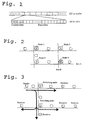
- the channels on the physically shared medium are realized by a time division multiplexing (TDM) scheme ( Figure 1).
- TDM time division multiplexing
- Figure 1 The total capacity is divided into cycles of 125 microseconds which are further divided into 64-bit slots.
- the slots are separated into data and control slots.
- Each node has access to at least one control slot, which is used for sending control information to the other nodes.
- Control messages can be sent upon request from a user, in response to control messages from other nodes or spontaneously for management purposes.
- the control slots constitute a small fraction of the total capacity, while the major part of the slots are data slots carrying payload.
- the data slots are allocated to the nodes according to some predefined distribution. This means that each node "owns" a portion of data slots.
- a node needs ownership of a slot to send data in it, and the ownership of slots may change dynamically among the nodes during the operation of the network.
- DTM uses a distributed algorithm for slot reallocation, where the pool of free slots is distributed among the nodes.
- the main drawback of a distributed implementation is the overhead of communication and synchronization between nodes.
- the node At the reception of a user request, the node first checks its local pool to see if it has slots enough to satisfy the request and, if so, immediately sends a channel establishment message to the next hop. Otherwise the node first has to request more slots from the other nodes on the bus.
- Each node maintains a status table that contains information about free slots in other nodes, and when more slots are needed the node consults its status table to decide which node to ask for slots. Every node regularly sends out status messages with information about its local pool of slots. Status messages have lower priority than other control messages so they are only sent when the control slot otherwise would be unused. Furthermore, the reallocation algorithm does not depend on nodes to process all status messages, so a node can safely ignore status messages while it is busy.
- the procedure for slot reallocation is simple and works as follows: if a user requests a channel with M slots and the node has N free slots, where , it sends requests asking for slots. The node starts by sending a request to the closest node with free slots. If this node does not have sufficiently many free slots, according to the status table, a request is sent also to the second closest node with free slots, and so on. The node waits until a response for each of the requests has been received and then grants or rejects the channel request, depending on the outcome of the reallocation procedure.
- a node that has some amount J of free slots and receives a slot reallocation request for K slots will always give away min(J, K) slots.
- the node responds by sending a slot reallocation confirmation, which indicates what slots the node gives away. If the requested node does not have any free slots, it responds with a slot reallocation reject instead.
- resources may be controlled by a network management system. For example, to prevent the network from starvation, a node can be configured not to give away all its slots, but to keep a certain fraction of its initial share.
- a DTM network can be expanded by interconnecting several buses with switch nodes (see Figure 2).
- DTM uses decentralized switching in the sense that any node connected to two or more buses can switch data between them.
- the switching is synchronous, which means that the switching delay is constant for a channel. This means that a multi-hop channel has roughly the same properties as a channel on a single bus. The only difference is that a switched channel has slightly longer delay (up to 125 microseconds for each hop). Provided that a switch node can buffer one cycle of data for each of its buses, there cannot be any congestion or overflow in the node.
- the synchronization between buses is done on a per cycle basis-cycles are started with the same frequency on all buses. This is accomplished by letting one network node be responsible for generating the cycles periodically on all its outgoing buses. For each new cycle, this node generates a cycle-start marker that is forwarded to all buses in the network. For each bus there is one switch node that is responsible for forwarding the marker onto the bus. Those switch nodes need to be organized in such a way that the marker reaches every bus exactly once. When the marker reaches a bus, the cycle is restarted on this bus.
- the cycle time and the slot size are both constant for all buses, which means that the synchronization scheme allows different buses to run at different bit rates. This makes it possible to upgrade or reconfigure individual buses in a network without affecting the rest of the network.
- the channel abstraction in DTM differs from ordinary circuits, in that channels have the following properties.
- a node creates a channel by allocating a set of data slots for the channel and by sending a channel establishment control message.
- the control message is addressed either to a single node or to a multicast group, and announces that the channel has been created and what slots it uses.
- switch nodes allocate slots for a channel on behalf of the sender.
- the switch nodes then start switching the channel, by copying the channel's slots from the incoming to the outgoing bus.
- An attempt to establish a multi-hop channel fails if any of the switch nodes involved cannot allocate the required amount of slots. In this case another route has to be tried.
- a grid structure there are normally several routes between each pair of nodes.
- the current version of the protocol uses source routing together with an addressing scheme based on (x, y) coordinates in the grid.
- a simple load-balancing scheme for two hops is achieved by letting each switch node use status messages to send information about the amount of free slots on its outgoing buses. For example, there are two possible routes between node 1 and node 4 in Figure 2, so if node 1 wants to set up a connection to node 4 it can choose between using switch node 2 and switch node 3. Node 1 receives status information from node 2 and 3, and can make its routing decision based on this information. This algorithm works well for dense grid networks, where most routes use only two hops, but a general routing algorithm is required for more arbitrary topologies.
- a traditional circuit is a point-to-point connection between a sender and a receiver.
- DTM uses a shared medium which inherently supports multicast since a slot can be read by several nodes on a bus.
- a multicast channel can easily be extended to span over several hops, since the switch operation is actually a multicast operation, in the sense that it duplicates data onto another bus (see Figure 3).
- nodes receive transfer requests from a traffic generator and control messages from other network nodes. These events are put in an input queue at the node, and the node processes one event at a time. The time to process one event is 5 microseconds. Transfer requests are generated by Poisson processes, and source and destination addresses are uniformly distributed. For each transfer request, a node attempts to allocate slots and, if that succeeds, establishes the channel, transfers the data and takes down the channel. This means that slots are released as soon as the transfer is done.
- the simulations are performed for different transfer sizes (1 to 256 kilobytes), for different kinds of user requirements, and for different inter-node distances (0.01 to 10 kilometers).
- the link bit-rate is 4.8 Gbps, which gives a slot rate of 75 MHz and a cycle size of 9600 slots.
- Each transfer requests 40 slots per cycle. This corresponds to 20.48 Mbps channels, which means that a 16 kilobyte transfer, for example, takes about 6 milliseconds.
- the grid has more nodes than the single dual bus, but fewer nodes per bus (20 instead of 100). Since the traffic load on a bus is distributed over its nodes, this means that at a given bus load, the grid will have more traffic to and from each node. A node in the grid therefore needs more control slots. However, a node has limited capacity to process control messages, and we have found that with 5 microseconds event processing time, very little performance is gained by using more than 10 control slots per node. We therefore use 10 control slots per node in the grid, which gives a maximum possible throughput of 0.98.
- Access delay is the average time from the time that a request arrives to the node until the data transfer starts. It is a measure of the overhead at channel establishment and includes the time it takes to allocate slots, send a channel establishment message to the receiver, and send the first slot of data.
- the sender waits for a confirmation from the receiver that the channel has been established on both buses before it starts sending data.
- the sender alone creates the channel to the receiver, and can therefore start sending data as soon as the slots have been allocated.
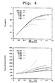
- the first set of simulations concerns performance of one dual bus.
- the purpose of these simulations is mainly to study slot allocation schemes for different user requirements. Since slot allocations on different buses are independent operations, these results are generally applicable for the multi-hop cases as well.
- Figure 4 shows the results of a basic simulation where a node makes at most one attempt to allocate the requested capacity for a channel, and rejects the request if the full requested capacity cannot be allocated. Transfer sizes between 1 and 256 kilobytes are simulated. The simulations could not be carried out for the smallest transfers (1 and 2 kilobyte in Figure 4) at high load, due to the simulator event queue growing too large, indicating that the control capacity is exhausted.
- the access delay consists, at low load, mainly of the time it takes for a node to process the transfer request, wait for the first available control slot (for the channel establishment message), and then for the first data slot (80 microseconds together, on the average).
- the load increases, nodes have to request slots from other nodes and more delay is introduced.
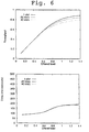
- Figure 5 shows throughput and access delay for different values of the maximum number of retries allowed.
- nodes are allowed to retry, more channels can be established and throughput increases (up to 92% of the maximum possible throughput), but at the expense of longer access delay and more signaling.
- retry is best suited for applications that have strict bandwidth demand but can tolerate some access delay.
- Figure 5 shows that performance decreases when the load is high and nodes are allowed to retry 20 times, which indicates that the signaling capacity is not sufficient for 20 retries.
- FIG. 6 shows throughput and delay for three cases: when the user is satisfied with any capacity (minimum 1 slot), requires at least half the requested capacity (20 slots), and needs the full capacity (40 slots). Throughput goes up when the user is less demanding. When the user requires only one slot, the throughput achieved is 94% of the maximum possible throughput.
- the slot reallocation procedure is however the same in all three cases, which explains why access delay is practically the same in the three cases.
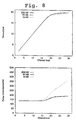
- Figure 8 shows the result of a simulation for multi-hop channels.
- the network is a fully connected grid network with 20 x 20 nodes. Channels use at most two hops, and the routing decision is based on the information from status messages.
- the slot allocation principle is the same as in Figure 4, that is, strict demand without retry.
- the access delay for a multi-hop channel will be longer than on a single hop, since slots have to be allocated on two buses. For 256 kilobyte transfers, the access delay is roughly 50 per cent longer in the multi-hop case compared to the single hop case. One could expect the access delay in the grid to be longer than this. There are two main reasons why this is not the case. First, there is a certain amount of parallelism in channel establishment over two hops. Second, the interval between control slots is shorter in the grid, so a node spends less time waiting for control slots. For 16 kilobyte transfers, however, the delay increases dramatically for higher load, which indicates that signaling capacity is insufficient.
- the Dynamic synchronous Transfer Mode is a network architecture for integrated services. It is based on fast circuit switching, and provides multi-rate, multicast channels with short set-up time. A channel gives guaranteed capacity and constant delay, which makes it well suited for real-time traffic, such as video and audio. In contrast to traditional circuit-switched networks, DTM also provides dynamic reallocation of resources between nodes in order to support dynamically varying traffic.
- the basic topology of a DTM network is a bus with two unidirectional optical fibers connecting all nodes.
- busses with different speeds may be connected together to form an arbitrary multistage network.
- buses can be combined into a two-dimensional mesh.
- a node at the junction of two buses can synchronously switch data slots between the two busses. This allows for efficient switching with constant delay through the node.
- the primary communication abstraction in DTM is a unidirectional, multi-rate and multicast channel.
- the DTM medium access protocol is a time-division multiplexing scheme.
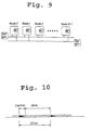
- the bandwidth of the bus is divided into 125 us cycles (Fig. [10]), which in turn are divided into 64-bit time slots (or slots for short).
- the number of slots in a cycle thus depends on the network's bit-rate; for instance, on a 6.4 Gbit/s network there are approximately 12500 slots per cycle.
- the slots are divided into two groups, control slots and data slots.
- Control slots are used to carry messages for the network's internal operation, such as messages for channel establishment and bandwidth reallocation.
- the data slots are used to transfer user data and are not interpreted by intermediate network nodes. Intermediate nodes are nodes between the source and destination.
- each network node there is a node controller, which controls the access to data slots and performs network management operations, such as network start-up and error recovery.
- the main tasks of the node controller are to create and terminate channels on demand from users, and to manage network resources in response to user requests and in the background.
- Control slots are used exclusively for messages between node controllers. Each node controller has write permission to at least one control slot in each cycle, which it uses to broadcast control messages to downstreams nodes. Since write access to control slots is exclusive, the node controller always has access to its control slots, regardless of other nodes and network load. The number of control slots a node uses may vary during network operation.
- the majority of the slots in a cycle are data slots. Access to data slots changes over time, according to traffic demands. Write access to slots is controlled by slot tokens (or tokens for short). A node controller may write data into a slot only if it owns the corresponding token. The token protocol guarantees the slot access to be conflict free, which means that at most one node writes data into the same slot.
- Control messages for channel establishment and bandwidth reallocation carry sets of tokens as parameters.
- a control message is 64 bits and can therefore have only a small number of parameters. This means that if a user requests a large bandwidth transfer, it may be necessary to send several control messages to create the channel. This introduces extra access delay and consumes signaling capacity.
- a block token is transferred in a single control message and represents a group of tokens, but can only be used for particular combinations of tokens. For instance, in the network simulations described in this paper, a block token is denoted by a slot number and an offset giving the number of contiguous slots in the group.
- the block token optimization assumes that the token pool is not fragmented into small pieces. The amount of small token blocks in the free pool, may be a problem and will be referred to as fragmentation.
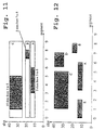
- Fig.11 shows an example of how three tokens (A, B, and C) are reserved for three channels. Nodes are connected by bus segments and channels typically use a subset of the segments on the bus (gray color) and the rest are reserved (white color) but left unused and thus wasting shared resources. A better alternative is to let channels only reserve capacity on the segments between the sender and the receiver as the example in Fig.12. A single slot may in this case be used multiple times on the bus. Channel D and E are using the same slots as channel A and C but on different segments. This is referred to as slot reuse. Slot reuse enables simultaneous transmissions in the same slot over disjoint segments of the bus.
- Slot reuse is a general method to better utilize shared links in ring and bus networks.
- the slot reuse algorithms in DQDB Distributed Queue Dual Bus
- Simple and CRMA Compute Reservation Multiple Access
- Buffer insertion networks when combined with destination release as in METARING may reuse capacity of individual links and resolve eventual contention by delaying the incoming packet stream through an elastic buffer.
- slot reuse With slot reuse, the access scheme complexity is increased, regardless of whether it is done in hardware as in DQDB, Simple, and CRMA, or in software, as in DTM.
- slot reuse When implemented in systems other than DTM, slot reuse also adds complex hardware to the critical high-speed path through a node and therefore increases the node delay.
- the block token format is extended to include parameters describing the segment(s) it is representing.
- the token management protocol is also modified to avoid conflicts in the slot number dimension as well as the segment dimension. The most important assumption is that no hardware changes to the original prototype implementation were allowed or needed. The performance gain is also quite clear: on a dual-bus where source and destination pairs are uniformly distributed, it has been shown that throughput may be increased by a factor of two.
- the potential drawback of slot reuse in a DTM network is the higher algorithm complexity and potentially higher load on the node controller and signaling channels (especially if the average channel duration is short).
- the node Each time a user request arrives at a node, the node first requests tokens from the manager and then locks them throughout the channel life-time. When the user issues a request to disconnect the channel, the tokens are immediately returned to the manager. All requests are delayed during the token request and accesses are serialized through the central manager.
- the distributed token manager is fundamentally more complicated than the centralized. We tried to keep it as simple as possible. In our method each node regularly broadcasts status information about how many free tokens it has. The other nodes store this information in their status tables. A node that wants more capacity consults its status table to decide from which node to request slots.
- the protocol on the 'initiating side works as follows, when a user request arrives to a node:
- a node fulfills incoming requests in strict FIFO order (First In First Out).
- a node When a node receives a response to a token request, it marks the slots it receives in the response (if any) as being reserved. When the node has received responses to all requests it has sent, it either starts the channels or rejects the user request, depending on if it has acquired sufficient capacity. If the user request is rejected, the reserved slots are marked as free.
- each node takes at least one of its free tokens, moves it (them) to the active state and declares it (them) to be a control slot.
- User requests may now be accepted and tokens can be moved between nodes on demand.
- the local node contains enough tokens to fulfill an arriving user request, the request may be accepted without any token reallocation.
- the pool of free tokens can be distributed in other ways than uniformly to increase the speed for successful reallocation and usage. If fewer nodes are managing the pool, the channel blocking is decreasing as a result of lesser possibility for tokens to be wrongly reallocated.
- the complete token pool is in this case proportionally distributed (nodes near the slot generator will have more tokens than nodes far away from this) among all nodes.
- the transfers of nodes can occur between each pair of nodes in place of always use the server node.
- the local node comprises sufficient number of tokens to satisfy an arriving user request, the request can be accepted without any token reallocation. Further, as long as the arriving user requests are well matched by the pool distribution, no reallocation will ever be necessary.
- Status message information is used to help a node choose a suitable node when asking for more resources. This method addresses the first question above.
- Status tables are "soft" information in the sense that the system will work even if they are out of date or unavailable. They should, however, improve the success rate of reallocation procedures.
- a node uses the status table to pick node(s) from which to request tokens. When the request reaches the target node the amount of available capacity may have changed and a smaller amount than requested may be returned to the requesting node, resulting in a user rejection.
- the size of the average pool will be relatively small. When the load is high, the number of free tokens in the pools will decrease even further. If nodes also create and destroy channels at a very high speed, the amount of free capacity in individual nodes will vary between a little amount of capacity and no capacity at all. If now the average capacity which is requested by a user is large in comparison with the number of free tokens of a node, then more nodes must be asked to fulfill the request. At this time the possibility that the requested nodes have no free capacity will lead to a user reject.
- defragmentation scheme that tries to avoid fragmentation if possible and increases the average block size of free tokens in the nodes.
- the scheme is used both with and without slot reuse.
- This scheme returns tokens to "home" nodes as a way to increase the probability that two consecutive tokens can be merged in the free list. If home node "gravity" is too strong, the scheme will result in less sharing of resources and unnecessary signaling. If it is too weak, fragmentation will still remain a problem.
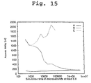
- the simulator A was configured to not have any fragmentation at the start time for simulation and to use the defragmentation plan described above, B started with maximal fragmentation of the complete resource pool. All the tokens had only one slot and no tokens in the home nodes were connected before the defragmentation mechanism. Finally, the simulator C was started without the use of the defragmentation mechanism and with the pool which has the maximal fragmentation. In all the cases the slot reuse was switched on and the load was defined to be 80%.
- Access delay as a function of simulated time is disclosed in fig. 15 for a network of 10 km.
- the simulator C started with a long access delay and the delay increased when the signal channels were overloaded and the message queues increased.
- the simulator B utilizing the defragmentation mechanism starts exactly as badly as C, but already after 10 ms the average access delay is below 500 ms. Later, when a second of simulated time had elapsed, the B-curve is connected in the most nearest with A, i.e. it converges if the performance of the simulator is started without any fragmentation at all.
- the converging speed depends on the amount of free capacity in the network and consequently on the load. The load during all these simulations was 80%.
- the defragmentation mechanism clearly improves the access delay and does even do the block token optimization meaningful in the distributed realization.
- Utilization is the portion of the nominal network capacity that is actually used for data transfer, and is a measure of the efficiency of the network.
- Access delay is the time from the arrival of a user request to the sending of the first data of the request, which we think is an important measure for how well computer communication traffic can be supported.
- each node is assigned signaling capacity in the form of control slots, which means that there are fewer slots available for data transfer on a bus with many nodes, given a fixed link capacity.
- token reallocation incurs overhead since while a slot token is being reallocated between nodes, the corresponding slot cannot be used for data transfer.
- Access delay depends mainly on the load on the control slots, and on how many control messages that need to be sent to establish a channel.
- the access delay is typically a summation of several delays (and typical values): Node controller processing delay [5 us], delay in finding and allocating free tokens [100 us], waiting for the first available control slot to pass [50 us], and finally waiting for the first allocated data slot to be filled with user data [62.5us].
- messages are delayed in queues at the input to node controllers waiting to be processed. In the simulations presented in section 5.2 the average delay is up to a few hundred microseconds.
- each transfer starts with the arrival of a new "packet" of information.
- the node controller tries to allocate resources for the transfer, transmits the packet and finally releases the channel.
- This is a simplification of the mechanisms in a real system, where channel set-up, data transfer and channel teardown are independent operations initiated by the user. For example, a user that knows that a transfer is about to take place may "hide" the channel establishment delay by requesting a channel in advance, so that it is already established when the transfer starts. Between a set-up and teardown, the capacity of the channel is completely reserved for the user. The most straight-forward use of the channel is for a single transfer, such as a file transfer or a video transmission.
- a channel may be used to transfer sequences of higher level messages such as ATM cells or IP packets. If it is a multicast channel, messages to different destinations can be multiplexed onto it. This means that each message will reach every receiver on the multicast channel and receivers must be able to filter messages.
- An alternative solution is to create and destroy a channel for each message, but reserve the tokens between messages so that the tokens are readily available for the next message in the sequence. We do not incorporate this type of user behavior in the simulations, since they are optimizations for particular applications. Instead we focus on how the network performs without user level optimizations.
- the sender may start sending data as soon as the resources are allocated, even before the receiver receives the channel establishment message. This is called fast channel establishment.
- the receiver will eventually respond with a control message to accept or reject the channel.
- the source and destination addresses are generated randomly (all nodes with the same probability) and user inter-arrival times are exponentially distributed.
- the simulations investigate the effect of signaling capacity and slot reallocation overhead on utilization, channel set-up delay, and blocking.
- We simulate a topology with the following characteristics:
- the maximum throughput of a dual-bus system without slot-reuse can be defined as twice the link capacity, given that both fibers receive the same traffic. In a system with slot reuse the system throughput also depends on the source destination distribution. To obtain this throughput for the dual-bus we used a Monte Carlo simulation where source and destination addresses were uniformly distributed (see left graph Fig.16). In the right graph in Fig.16, performance of a DTM network is included. The DTM network uses a centralized token manager and users request to transfer 4 Mbyte of information each time. In this system, signaling capacity is not a bottleneck and utilization is found to be close to the ideal case. Real traffic behaving like this is bulk-data transfers and audio/video streams.
- the two managing nodes need more signaling capacity than other nodes (we assign 8 times as many control slots to a server node than to other nodes).
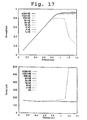
- Results of the first set of simulations are presented in Fig.17.
- Users request 20 Mbit/s channels, inter-arrival times are exponentially distributed (generated by a Poisson process) and the simulations are performed with different packet sizes. If the full capacity of the channel cannot be allocated, the request is rejected and tokens are returned to the token server. Packet sizes vary from 4 Mbyte to 2 kbyte, at which point we begin to see throughput degradation.
- Throughput degradation may occur if processing capacity in nodes or control channel capacity is too small.
- the server nodes may be especially overloaded. The result is that queues containing control messages start growing very big.
- the control tokens represent unused capacity, and therefore the throughput is degraded.
- control capacity is the limiting factor and if more control slots (signal capacity) are added, 4 kbyte and even smaller packets can be more efficiently supported.
- each channel establishment requires a token to be requested from the server. If the length of the bus is increased, the token request will take a longer time and may therefore also limit the throughput and increase the access delay.
- Access delay in this case depends on the distance to servers, but is independent of the transfer size.
- Throughput depends strongly on the average transfer size as the establishment phase is amortized over the data transfer phase.
- Channels transferring large amounts of information such as 256 kbyte with a duration of one tenth of a second are still efficiently supported when the bus length is 1000 km.
- Utilization of a centralized token manager has several benefits. Clients may be simple as they only contain state information related to their own opened channels. Slot reuse is also simple and efficient, as the slot server has all of the free tokens to choose from when trying to satisfy a user request. The server may also implement other policy related functions such as admission control and fairness. The fragmentation of the free token pool in the server is normally very modest, resulting in very few connection establishment messages per channel even for high capacity user requests.
- a user that frequently establishes and destroys channels may introduce excessive signaling by always returning tokens after use, but then requesting the tokens again within a short time period.
- the processing capacity of the server node may get overloaded if there are many nodes on the bus or if the average packet size is very small. If the media length is very large relative to the product of bit-period, bits-per-packet and media velocity, the round trip time to the server may also limit performance.
- the server node contains state information that all nodes depend on to create channels. A server node failure may therefore affect all the nodes.
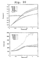
- Fig.20 The results presented in Fig.20 are from the simulations with slot reuse, a fully distributed token manager, status messages which describe how much capacity a node possesses, and the defragmentation scheme. All the nodes have the same process capacity and the process load is much lower than the load the servers in fig.18 are receiving. The dependencies between nodes are also much lower, which results in a higher extent of reliability. The system performs better than any system without slot reuse, but not as well as the centralized system described earlier.
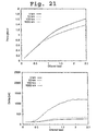
- the throughput and access delay of the distributed token manager with varying bus lengths from 1 km to 1000 km are presented in Fig.21.
- a 16 kbyte packet is sent between establishment and tear-down of the channel.
- the 1 km and 100 km buses give about the same throughput and access delay as the 10 km bus, because the latency introduced by using a 125 us cycle dominate over the time of flight latency in the system.
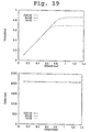
- the access delay is found to be shorter than in the 1000 km system using a centralized token server (see Fig.19).
- a centralized token server see a centralized token server.19.
- the access delay is about the same for all systems independently of bus length. Even at very high load the access delay is about 1 millisecond shorter than it is in the centralized system in Fig.19
- the centralized token manager system will have the same performance almost independently of the traffic as long as processing and signaling are sufficient.
- Second, to generate traffic more similar to client-server behavior we increase the amount of traffic arriving to 5 server nodes, 0, 25, 50, 75, and 99. Even the probability for a server destination is also higher.
- the nodes may share the processing load, there is less need for high-performance token servers, redundancy may be higher and access delay may be shorter for low capacity request. It also scales to longer busses. The drawback is higher blocking. It is also clear that the status messageand status table mechanism must be changed to avoid unnecessary blocking when slot reuse is allowed.
- the distributed scheme is more sensitive to user behavior, relies on status information that is broadcast frequently, and needs a defragmentation scheme.
- the main advantage with the distributed scheme is that it efficiently decouples the access delay from the round-trip time on the bus.
- channel establishment overhead can be very small, resulting in high utilization even for small (a few kilobytes) transfers.
- Access delay is found to be a few hundred microseconds even at high load.
- the slot reuse scheme can increase the throughput performance by a factor of two and can be implemented without introducing any extra hardware in the nodes.
- the network is not limited to a dual bus, but can be realized with all types of structures, e.g. a ring structure with an arbitrary number of nodes.
- the transmission medium can, except optical fiber, be coaxial cable or another transmission medium with a high bandwidth. In the description the transmission medium will be referred to as optical fiber.
- the bandwidth of the DTM dual bus is, in the preferred embodiment, partitioned in 125 ⁇ s cycles, which in turn are partitioned in time slots of 64 bits.
- the present invention is not limited to DTM networks with these values, but can be used in networks with cycles and time slots with arbitrary size.
- the increase of performance with time slot reuse is clear: at a dual bus where the source and destination pairs are distributed uniformly the throughput has proved to increase with a factor two.
- the increase of performance can be even higher in other types of networks; i.e. in a dual ring structure with the source and destination pairs distributed uniformly, the throughput can be increased with a factor 4.
- the simulations described above have shown that the fast circuit-switched protocol of DTM performs well in a dualbus-divided medium environment.
- Two time slot management schemes are analyzed and both are performing well and can take advantage of time slot reuse.
- the centralized scheme acts nearest the ideal protocol and is at the same time easier to implement.
- the distributed system is more sensitive to user performance and must therefore rely upon status information which is sent frequently, and upon the defragmentation mechanism to decrease the number of control messages needed for channel establishing and timeslot reallocation.
- By using the distributed model with defragmentation mechanism on long buses better performance can be achieved than when using the centralized model.
- a resource management system which combines the centralized and the distributed model is also possible by using a smaller set of token server nodes.
- connection establishing overhead can be very low, which results in a high degree of utilization even for small (a few kbyte) transfers.
- the access delay is some hundred micro seconds even at high loads.
- the time slot reuse method can increase the performance with a factor two (on a dual bus) without the adding of additional hardware to the nodes. When the time slot reuse method is used it is even more important to use the defragmentation method because fragmentation can be performed both in time slot and segment way.
- nodes In the completely distributed system all nodes are home nodes (server nodes) and tokens are evenly distributed among all the home nodes.
- tokens can even be moved back to their home nodes after the elapse of a significant time (e.g. when they have been free (idle) a certain time, so called “idle-time” or when they have not been in their home node for a certain time, so called “last home-time”).
- a significant time e.g. when they have been free (idle) a certain time, so called “idle-time” or when they have not been in their home node for a certain time, so called “last home-time”).
- the number of home nodes can vary from 1 to the overall number of nodes.
- the gravitation can independently vary from 0 to infinity.
- a uniting of adjacent block tokens, the uniting in segment direction ought to be prioritized before uniting in time slot direction.
- fig. 23 there is disclosed a token graph with two time slot sensequtive block tokens A and B. Normally no partitioning/uniting is performed because the segments then would be shorter.
- fig. 26 there is disclosed two block tokens H and I.
- the requested capacity corresponds to half of H and all of I and shall be sent from node A, NA to node B, NB.
- H is chosen for transportation, which is partitioned according to the broken line.
- a token I In fig. 27 there is disclosed a token I.
- the requested capacity corresponds to half of I and shall be sent from node A, NA to node B, NB.
- a part of I is chosen for transportation, which part is laid in the upper side or as in fig. 27 in the lower side of I.
- the remaining part must then be partitioned (the block token is normally rectangular). Preferably, this is performed according to the broken line to preserve as large a segment as possible.
- the status table only contains information about time slots which are free over all segments.
- node O, NO has access to the capacity (b-a) and over all segment, but shall send the capacity (b-a) only to node N, NN, then it has no use of the segments NN and thereover. These can then be sent to NN for future demands.
- node N, NN has access to the capacity (time slots) (d-c) and shall send this capacity to node M, NM, then it will send even the free segments NM and thereover to the node M, NM for future demands.
- the token block (NO-NN)*(d-c) will be sent down to the node O, NO, for eventual future demands. In this connection there is required extra signaling whereby this token block (NO-NN)*(d-c) can be sent with an eventually lower priority.
Landscapes
- Engineering & Computer Science (AREA)
- Computer Networks & Wireless Communication (AREA)
- Signal Processing (AREA)
- Small-Scale Networks (AREA)
- Data Exchanges In Wide-Area Networks (AREA)
- Computer And Data Communications (AREA)
- Preparation Of Compounds By Using Micro-Organisms (AREA)
Claims (38)
- Méthode de gestion centralisée de la capacité dans un réseau à circuits commutés avec une structure à bus ou à anneau, lequel réseau utilise une largeur de bande qui est divisée en cycles, qui à leur tour sont divisés en créneaux de temps de contrôle pour la signalisation et en créneaux de temps de données pour le transfert de données, et dans laquelle chaque créneau de temps de données est associé à un jeton,
caractériséeen ce qu'à un premier noeud, appelé noeud serveur, sont affectés des jetons correspondant à tous les créneaux de temps de données qui circulent dans une direction dans un bus ou dans un anneau,en ce qu'un second noeud requiert des jetons correspondant à une certaine capacité du noeud serveur,en ce que le noeud serveur fait des réservations pour des jetons et transfère des jetons correspondant à la capacité nécessaire pour l'autre noeud, dans le cas où la capacité requise est inutilisée dans le noeud serveur, eten ce que les jetons transférés sont retransmis au noeud serveur et sont libérés, si les créneaux de temps de données correspondants n'ont pas été utilisés pour transférer des données de l'autre noeud durant un laps de temps important. - Méthode selon la revendication 1, caractérisée en ce que la méthode est mise en application dans un réseau de type DTM (Mode de Transfert Synchrone Dynamique).
- Méthode selon la revendication 1 ou 2, caractérisée en ce que les jetons transférés sont retransmis au noeud serveur et sont libérés lorsque les créneaux de temps de données correspondants ne sont plus utilisés pour transférer des données.
- Méthode selon l'une quelconque des revendications 1-3, caractérisée en ce que le noeud serveur est choisi comme étant le noeud ayant 1/3 des noeuds situés en amont et 2/3 des noeuds situés en aval.
- Méthode de gestion répartie de la capacité dans un réseau à circuits commutés avec une structure à bus ou à anneau, dans laquelle la largeur de bande est divisée en cycles, qui à leur tour sont divisés en créneaux de temps de contrôle pour la signalisation et en créneaux de temps de données pour le transfert de données et dans laquelle chaque créneau de temps de données est associé à un jeton (accès d'écriture),
caractériséeen ce qu'au moins deux noeuds, appelés noeuds serveurs, sont définis entre ceux qui sont des jetons répartis correspondant à tous les créneaux de temps de données qui circulent dans une direction dans un bus ou dans un anneau,en ce qu'un noeud demande des jetons correspondant à une certaine capacité d'au moins l'un des noeuds serveurs,en ce que ce noeud serveur fait des réservations pour des jetons et transfère au noeud requérant des jetons correspondant à la capacité nécessaire, dans le cas où la capacité requise est inutilisée dans le noeud serveur, eten ce que les jetons transférés sont retransmis au noeud serveur respectif et sont libérés, si les créneaux de temps de données correspondants n'ont pas été utilisés pour transférer des données durant un laps de temps important. - Méthode selon la revendication 5, caractérisée en ce que la méthode est mise en application dans un réseau de type DTM (Mode de Transfert Synchrone Dynamique).
- Méthode selon la revendication 5 ou 6, caractérisée en ce que plusieurs noeuds serveurs sont demandés, font des réservations pour des jetons et transfèrent au noeud demandeur des jetons, qui correspondent ensemble à la capacité totale requise, dans le cas où la capacité requise est inutilisée dans l'ensemble des noeuds serveurs.
- Méthode selon l'une quelconque des revendications 5-7, caractérisée en ce que des jetons reçus sont utilisés pour installer des canaux en envoyant au noeud ou aux noeuds, qui sont désignés comme récepteurs de données, un message d'installation de canaux, dans le cas où un noeud a reçu des jetons correspondant à la capacité requise.
- Méthode selon l'une quelconque des revendications 5-7, caractérisée en ce qu'un ou plusieurs noeuds serveurs font des réservations pour des jetons et transfèrent au noeud demandeur des jetons, qui correspondent à la totalité de la capacité inutilisée, dans le cas où la capacité requise n'est pas inutilisée dans l'ensemble des noeuds serveurs.
- Méthode selon l'une quelconque des revendications 5-7, caractérisée en ce qu'un ou plusieurs noeuds serveurs ne transfèrent aucun jeton au noeud demandeur, dans le cas où la capacité requise n'est pas inutilisée dans l'ensemble des noeuds serveurs.
- Méthode selon la revendication 9 ou 10, caractérisée en ce que d'autres jetons sont requis par un noeud, dans le cas où les jetons éventuellement reçus ne correspondent pas à la capacité requise.
- Méthode selon la revendication 9 ou 10, caractérisée en ce que les jetons reçus dans un noeud sont libérés, dans le cas où ces jetons ne correspondent pas à la capacité requise.
- Méthode selon la revendication 9 ou 10, caractérisée en ce que des jetons reçus sont utilisés pour installer des canaux en envoyant au noeud ou aux noeuds, qui sont désignés comme récepteurs de données, un message d'installation de canaux, dans le cas où un noeud n'a pas reçu de jetons correspondant à la capacité requise.
- Méthode selon l'une quelconque des revendications 5-13, caractérisée en ce que chaque noeud serveur envoie régulièrement au reste des noeuds des informations concernant sa capacité inoccupée et en ce que chaque noeud mémorise les informations reçues des autres noeuds dans une table d'état.
- Méthode selon l'une quelconque des revendications 5-14, caractérisée en ce qu'un noeud requiert des jetons de la part du noeud serveur qui dispose pour le moment de la capacité inutilisée la plus importante.
- Méthode selon l'une quelconque des revendications 5-14, caractérisée en ce qu'un noeud requiert des jetons de la part du noeud serveur qui est le plus proche et dans lequel la capacité requise est inutilisée pour le moment.
- Méthode selon la revendication 15 ou 16, caractérisée en ce que le noeud serveur auquel la capacité est demandée peut être trouvé en se référant à la table d'état.
- Méthode selon l'une quelconque des revendications 5-17, caractérisée en ce que tous les noeuds dans un bus ou un anneau sont définis comme noeuds serveurs et qu'il leur est affecté au moins un jeton.
- Méthode selon la revendication 18, caractérisée en ce que dans un bus ou un anneau le même nombre de jetons est affecté à tous les noeuds.
- Méthode selon l'une quelconque des revendications 5-19, caractérisée en ce que les jetons transférés sont retransmis aux noeuds serveurs respectifs et sont libérés lorsque les créneaux de temps de données correspondants ne sont plus utilisés pour le transfert de données.
- Méthode selon l'une quelconque des revendications 5-19, caractérisée en ce que les jetons transférés sont libérés lorsque les créneaux de temps de données correspondants ne sont plus utilisés pour le transfert de données.
- Méthode selon l'une quelconque des revendications 1-21, caractérisée en ce que les jetons consécutifs dans un noeud sont représentés par un jeton appelé jeton bloc, qui est indiqué comme un numéro du premier créneau de temps dans une rangée et le nombre total de créneaux de temps dans la rangée.
- Méthode selon l'une quelconque des revendications 1-22, caractérisée en ce qu'un jeton est divisé en au moins deux jetons correspondant au même créneau de temps, mais à des segments différents, un segment se rapportant à une partie d'un moyen de transmission qui connecte au moins deux noeuds.
- Méthode selon l'une quelconque des revendications 1-23, caractérisée en ce que, dans le cas où il dispose de plusieurs groupes de jetons à créneaux de temps ou à segments consécutifs, parmi lesquels il peut choisir, le noeud serveur fait des réservations pour des jetons et transfère les jetons qui proviennent du groupe le moins important de jetons à créneaux de temps ou à segments consécutifs et qui correspond à une demande de capacité et dans laquelle le groupe le moins important est défini comme étant le groupe dont le produit des créneaux de temps et des segments ayant des importances prédéterminées est le plus bas.
- Méthode selon l'une quelconque des revendications 1-24, caractérisée en ce que des groupes de jetons, qui sont au moins partiellement à segments consécutifs, sont regroupés pour agrandir le nombre de segments consécutifs pour chaque groupe de jetons et l'ampleur du nombre de créneaux de temps consécutifs.
- Unité de contrôle de noeuds dans un noeud dans un réseau à circuits commutés avec une structure à bus ou à anneau, lequel réseau utilise une largeur de bande qui est divisée en cycles, qui à leur tour sont divisés en créneaux de temps de contrôle pour la signalisation et en créneaux de temps de données pour le transfert de données et dans laquelle chaque créneau de temps de données est associé à un jeton, caractériséeen ce qu'à l'unité de contrôle de noeuds sont affectés des jetons correspondant à un nombre prédéterminé de créneaux de temps de données qui circulent dans une direction dans un bus ou dans un anneau,en ce que l'unité de contrôle de noeuds est agencée pour faire des réservations pour des jetons et pour transférer des jetons à une seconde unité de contrôle de noeuds dans un second noeud, dans le cas où elle reçoit une demande pour des jetons de la part de la seconde unité de contrôle de noeuds et qu'elle dispose de la capacité requise non utilisée eten ce que la seconde unité de contrôle de noeuds est agencée pour retransmettre les jetons transférés à l'unité de contrôle de noeuds et pour les libérer, si les créneaux de temps de données correspondants n'ont pas été utilisés pour transférer des données de la seconde unité de contrôle de noeuds durant un laps de temps important.
- Unité de contrôle de noeuds selon la revendication 26, caractérisée en ce que le réseau est du type DTM (Mode de Transfert Synchrone Dynamique).
- Noeud, également appelé noeud serveur, dans un réseau à circuits commutés avec une structure à bus ou à anneau, lequel réseau utilise une largeur de bande qui est divisée en cycles, qui à leur tour sont divisés en créneaux de temps de contrôle pour la signalisation et en créneaux de temps de données pour le transfert de données et dans lequel chaque créneau de temps de données est associé à un jeton, caractérisé par une unité de contrôle de noeuds à laquelle sont affectés des jetons correspondant à un nombre prédéterminé de créneaux de temps de données qui circulent dans une direction dans un bus ou dans un anneau et qui est agencée pour faire des réservations pour des jetons et pour transférer des jetons à une seconde unité de contrôle de noeuds dans un second noeud, dans le cas où elle reçoit une demande pour des jetons de la part de la seconde unité de contrôle de noeuds et qu'elle dispose de la capacité requise non utilisée.
- Noeud selon la revendication 28, caractérisé en ce que le réseau est du type DTM (Mode de Transfert Synchrone Dynamique).
- Noeud selon la revendication 28 ou 29, caractérisé en ce qu'au noeud sont affectés des jetons correspondant à tous les créneaux de temps de données qui circulent dans une direction dans un bus ou dans un anneau.
- Noeud selon la revendication 30, caractérisé en ce qu'un tiers des noeuds du bus ou de l'anneau est situé en amont et deux tiers des noeuds du bus ou de l'anneau est situé en aval.
- Réseau à circuits commutés d'une structure à bus ou à anneau, lequel réseau utilise une largeur de bande qui est divisée en cycles, qui à leur tour sont divisés en créneaux de temps de contrôle pour la signalisation et en créneaux de temps de données pour le transfert de données et dans lequel chaque créneau de temps de données est associé à un jeton, caractérisé par un noeud, également appelé noeud serveur, auquel sont affectés des jetons correspondant à un nombre prédéterminé de créneaux de temps de données qui circulent dans une direction dans un bus ou dans un anneau et qui est agencé pour faire des réservations pour des jetons et pour transférer des jetons à un second noeud, dans le cas où il reçoit une demande pour des jetons de la part du second noeud et qu'il dispose de la capacité requise non utilisée.
- Réseau à circuits commutés d'une structure à bus ou à anneau, lequel réseau utilise une largeur de bande qui est divisée en cycles, qui à leur tour sont divisés en créneaux de temps de contrôle pour la signalisation et en créneaux de temps de données pour le transfert de données et dans lequel chaque créneau de temps de données est associé à un jeton, caractérisé en ce qu'au moins deux noeuds, appelés noeuds serveurs, sont définis parmi ceux dans lesquels des jetons correspondant à tous les créneaux de temps de données, qui circulent dans une direction dans un bus ou dans un anneau, sont distribués et en ce que les noeuds serveurs sont agencés pour faire des réservations pour des jetons et pour transférer des jetons à un troisième noeud, dans le cas où les noeuds serveurs reçoivent une demande pour des jetons de la part du troisième noeud et qu'ils disposent de la capacité requise non utilisée.
- Réseau à circuits commutés selon la revendication 32 ou 33, caractérisé en ce que le réseau est du type DTM (Mode de Transfert Synchrone Dynamique).
- Réseau à circuits commutés selon l'une quelconque des revendications 32-34, caractérisé en ce qu'un noeud est agencé pour utiliser des jetons reçus pour installer des canaux en envoyant au noeud ou aux noeuds, qui sont désignés comme récepteurs de données, un message d'installation de canaux, dans le cas où le noeud a reçu des jetons correspondant à la capacité requise.
- Réseau à circuits commutés selon l'une quelconque des revendications 33-35, caractérisé en ce qu'un ou plusieurs noeuds serveurs sont agencés pour faire des réservations pour des jetons et pour transférer au noeud demandeur des jetons, qui correspondent à la totalité de la capacité inutilisée, dans le cas où l'ensemble des noeuds serveurs ne disposent pas la capacité requise non utilisée.
- Réseau à circuits commutés selon l'une quelconque des revendications 33-35, caractérisé en ce qu'un ou plusieurs noeuds serveurs sont agencés pour ne transférer aucun jeton au noeud demandeur, dans le cas où l'ensemble des noeuds serveurs ne disposent pas la capacité requise non utilisée.
- Réseau à circuits commutés selon l'une quelconque des revendications 33-37, caractérisé en ce qu'un noeud est agencé pour utiliser une table d'état, c'est-à-dire une liste régulièrement mise à jour de la capacité inutilisée de tous les noeuds serveurs, pour décider à quels noeuds serveurs doivent être demandés des jetons.
Applications Claiming Priority (3)
| Application Number | Priority Date | Filing Date | Title |
|---|---|---|---|
| SE9504681 | 1995-12-28 | ||
| SE9504681A SE515901C2 (sv) | 1995-12-28 | 1995-12-28 | Resursadministrering, plan och arrangemang |
| PCT/SE1996/001750 WO1997024846A1 (fr) | 1995-12-28 | 1996-12-23 | Procede et structure de gestion des ressources d'un reseau |
Publications (2)
| Publication Number | Publication Date |
|---|---|
| EP0873629A1 EP0873629A1 (fr) | 1998-10-28 |
| EP0873629B1 true EP0873629B1 (fr) | 2001-03-28 |
Family
ID=20400757
Family Applications (1)
| Application Number | Title | Priority Date | Filing Date |
|---|---|---|---|
| EP96944173A Expired - Lifetime EP0873629B1 (fr) | 1995-12-28 | 1996-12-23 | Procede et structure de gestion des ressources d'un reseau |
Country Status (10)
| Country | Link |
|---|---|
| US (1) | US5982780A (fr) |
| EP (1) | EP0873629B1 (fr) |
| JP (1) | JP2000502856A (fr) |
| AT (1) | ATE200170T1 (fr) |
| AU (1) | AU1404197A (fr) |
| CA (1) | CA2241554A1 (fr) |
| DE (1) | DE69612302T2 (fr) |
| ES (1) | ES2157019T3 (fr) |
| SE (1) | SE515901C2 (fr) |
| WO (1) | WO1997024846A1 (fr) |
Cited By (1)
| Publication number | Priority date | Publication date | Assignee | Title |
|---|---|---|---|---|
| RU2543570C2 (ru) * | 2012-04-10 | 2015-03-10 | Федеральное государственное казенное военное образовательное учреждение высшего профессионального образования "Военная академия войсковой противовоздушной обороны Вооруженных Сил Российской Федерации имени Маршала Советского Союза А.М.Василевского" Министерства обороны Российской Федерации | Способ управления обслуживанием запросов пользователей в информационно-вычислительном комплексе |
Families Citing this family (81)
| Publication number | Priority date | Publication date | Assignee | Title |
|---|---|---|---|---|
| US6381633B2 (en) * | 1997-05-09 | 2002-04-30 | Carmel Connection, Inc. | System and method for managing multimedia messaging platforms |
| JP3369445B2 (ja) * | 1997-09-22 | 2003-01-20 | 富士通株式会社 | ネットワークサービスサーバ負荷調整装置、方法および記録媒体 |
| EP0932259A1 (fr) * | 1998-01-27 | 1999-07-28 | Lucent Technologies Inc. | Décodage iterative à la demande |
| US6412006B2 (en) * | 1998-02-10 | 2002-06-25 | 3Com Corporation | Method and apparatus for sending delay sensitive information assisted by packet switched networks |
| GB2335580B (en) * | 1998-03-20 | 2003-03-12 | Ericsson Telefon Ab L M | Fair channel allocation protocol for dtm networks |
| SE513221C2 (sv) * | 1998-04-17 | 2000-07-31 | Net Insight Ab | Förfarande och anordning för allokering av tidluckor till en kanal i ett kretskopplat tidsmultiplexerat nät |
| SE513517C2 (sv) | 1998-09-10 | 2000-09-25 | Net Insight Ab | Förfaranden för ändring av bandbredden på en isokron kanal i ett kretskopplat nät |
| US6308209B1 (en) * | 1998-10-22 | 2001-10-23 | Electronic Data Systems Corporation | Method and system for measuring usage of a computer network by a network user |
| US6804251B1 (en) * | 1998-11-12 | 2004-10-12 | Broadcom Corporation | System and method for multiplexing data from multiple sources |
| DE19919177A1 (de) * | 1999-04-28 | 2000-11-02 | Philips Corp Intellectual Pty | Netzwerk mit mehreren Netzwerk-Clustern zur drahtlosen Übertragung von Paketen |
| US6571136B1 (en) * | 1999-06-19 | 2003-05-27 | International Business Machines Corporation | Virtual network adapter |
| US6970442B1 (en) | 1999-07-19 | 2005-11-29 | At&T Corp. | Multiple-access scheme for packet voice that uses voice activity detection |
| CA2379412C (fr) * | 1999-07-19 | 2007-06-05 | At&T Corp. | Schema a plusieurs acces s'appliquant a la transmission de signaux vocaux par paquets et utilisant la detection d'activite des signaux vocaux |
| SE517859C2 (sv) * | 1999-10-21 | 2002-07-23 | Ericsson Telefon Ab L M | Dynamisk allokering av dataströmmar i ramar representerad av rambeskrivande index |
| US6898205B1 (en) * | 1999-10-26 | 2005-05-24 | Nokia, Inc. | Robust transport of IP traffic over wdm using optical burst switching |
| US7333495B2 (en) * | 1999-10-27 | 2008-02-19 | Broadcom Corporation | Method for scheduling upstream communications |
| US6993007B2 (en) | 1999-10-27 | 2006-01-31 | Broadcom Corporation | System and method for suppressing silence in voice traffic over an asynchronous communication medium |
| US6999414B2 (en) * | 1999-10-27 | 2006-02-14 | Broadcom Corporation | System and method for combining requests for data bandwidth by a data provider for transmission of data over an asynchronous communication medium |
| SE9904025L (sv) * | 1999-11-05 | 2001-05-06 | Net Insight Ab | Förfarande i ett digitalt kommunikationssystem |
| SE9904026L (sv) | 1999-11-05 | 2001-05-06 | Net Insight Ab | Metod för styrning av resurser i ett kommunikationsnät |
| SE9904024L (sv) * | 1999-11-05 | 2001-05-06 | Net Insight Ab | Förfarande i ett digitalt kommunikationssystem |
| US6618389B2 (en) * | 1999-11-22 | 2003-09-09 | Worldcom, Inc. | Validation of call processing network performance |
| US6651242B1 (en) * | 1999-12-14 | 2003-11-18 | Novell, Inc. | High performance computing system for distributed applications over a computer |
| US6640275B1 (en) * | 1999-12-22 | 2003-10-28 | Nortel Networks Limited | System and method for data transfer between buses having different speeds |
| US6882623B1 (en) | 2000-02-08 | 2005-04-19 | Native Networks Technologies Ltd. | Multi-level scheduling method for multiplexing packets in a communications network |
| DE60137115D1 (de) * | 2000-02-15 | 2009-02-05 | Broadcom Corp | System und verfahren zur kombinierung von datenbandbreitenanforderungen von einem datenanbieter für nsmedium |
| US7020714B2 (en) * | 2000-04-06 | 2006-03-28 | Rensselaer Polytechnic Institute | System and method of source based multicast congestion control |
| US6553438B1 (en) * | 2000-04-24 | 2003-04-22 | Intel Corporation | Methods and system for message resource pool with asynchronous and synchronous modes of operation |
| US6594718B1 (en) * | 2000-04-29 | 2003-07-15 | Hewlett-Packard Development Company, L.P. | Arbitration scheme for equitable distribution of bandwidth for agents with different bandwidth requirements |
| FI109061B (fi) * | 2000-05-10 | 2002-05-15 | Nokia Corp | Resurssien varaaminen pakettiverkossa |
| FR2809899B1 (fr) * | 2000-06-05 | 2002-11-29 | Cit Alcatel | Systeme de gestion de connexion pour la gestion de reseaux de telecommunication |
| US6944152B1 (en) * | 2000-08-22 | 2005-09-13 | Lsi Logic Corporation | Data storage access through switched fabric |
| WO2002019132A1 (fr) * | 2000-09-01 | 2002-03-07 | Tut Systems, Inc. | Procede et systeme de compilation preliminaire des donnees de configuration pour un dispositif de communication de donnees |
| US7251224B2 (en) * | 2000-10-10 | 2007-07-31 | Intel Corporation | Communications meshes |
| EP1199848A3 (fr) * | 2000-10-17 | 2003-12-17 | Appairent Technologies, Inc. | Reseau partagé en temp pour l'access multiple universel |
| FI110903B (fi) * | 2000-10-30 | 2003-04-15 | Nokia Corp | Lähetysten ajoittaminen tietoliikennejärjestelmässä |
| AU2002214461A1 (en) * | 2000-11-10 | 2002-05-21 | Dynarc Ab | Method for prioritization of network resources in networks |
| US7773631B2 (en) * | 2001-02-15 | 2010-08-10 | Broadcom Corporation | Specialized data transfer in a wireless communication system |
| US20020186721A1 (en) * | 2001-03-09 | 2002-12-12 | Bohn David Weaver | Methods and systems for monitoring traffic received from and loading simulated traffic on broadband communication link |
| WO2003009538A1 (fr) * | 2001-07-20 | 2003-01-30 | Radiant Networks Plc | Reseaux mailles de telecommunications |
| US7606900B2 (en) * | 2001-07-27 | 2009-10-20 | International Business Machines Corporation | Regulating access to a scarce resource |
| US7606899B2 (en) * | 2001-07-27 | 2009-10-20 | International Business Machines Corporation | Regulating access to a scarce resource |
| JP3719398B2 (ja) * | 2001-08-17 | 2005-11-24 | ソニー株式会社 | データ伝送方法及び装置並びにデータ送受システム |
| US7194561B2 (en) | 2001-10-12 | 2007-03-20 | Sonics, Inc. | Method and apparatus for scheduling requests to a resource using a configurable threshold |
| US6961834B2 (en) * | 2001-10-12 | 2005-11-01 | Sonics, Inc. | Method and apparatus for scheduling of requests to dynamic random access memory device |
| US6578117B2 (en) | 2001-10-12 | 2003-06-10 | Sonics, Inc. | Method and apparatus for scheduling requests using ordered stages of scheduling criteria |
| US6804738B2 (en) | 2001-10-12 | 2004-10-12 | Sonics, Inc. | Method and apparatus for scheduling a resource to meet quality-of-service restrictions |
| US6697374B1 (en) | 2001-12-05 | 2004-02-24 | Flexlight Networks | Optical network communication system |
| KR100574733B1 (ko) * | 2002-03-27 | 2006-04-28 | 미쓰비시덴키 가부시키가이샤 | 통신 장치 및 통신 방법 |
| US20030200317A1 (en) * | 2002-04-19 | 2003-10-23 | Native Networks Technologies Ltd | Method and system for dynamically allocating bandwidth to a plurality of network elements |
| JP4181116B2 (ja) * | 2002-05-17 | 2008-11-12 | 株式会社エヌ・ティ・ティ・ドコモ | 送信順序のデフラグ方法 |
| US7126963B2 (en) * | 2002-05-23 | 2006-10-24 | International Business Machines Corporation | Apparatus, method and computer program to reserve resources in communications system |
| US7242687B2 (en) * | 2002-05-24 | 2007-07-10 | Intel Corporation | Method and system for distribution of session scheduling |
| KR100484305B1 (ko) * | 2002-11-26 | 2005-04-20 | 한국전자통신연구원 | 이중 링에서의 부하 분산과 공평성 제공을 고려한 자원할당 방법 |
| US7716061B2 (en) * | 2003-03-27 | 2010-05-11 | International Business Machines Corporation | Method and apparatus for obtaining status information in a grid |
| EP1465370B1 (fr) * | 2003-04-05 | 2013-07-24 | Mentor Graphics Corporation | Communication de données prévisible en temps réel sur un bus en serie |
| US7415527B2 (en) * | 2003-06-13 | 2008-08-19 | Satyam Computer Services Limited Of Mayfair Centre | System and method for piecewise streaming of video using a dedicated overlay network |
| US7665069B2 (en) * | 2003-10-31 | 2010-02-16 | Sonics, Inc. | Method and apparatus for establishing a quality of service model |
| US8504992B2 (en) | 2003-10-31 | 2013-08-06 | Sonics, Inc. | Method and apparatus for establishing a quality of service model |
| US9087036B1 (en) | 2004-08-12 | 2015-07-21 | Sonics, Inc. | Methods and apparatuses for time annotated transaction level modeling |
| US20050175027A1 (en) * | 2004-02-09 | 2005-08-11 | Phonex Broadband Corporation | System and method for requesting and granting access to a network channel |
| US20050208949A1 (en) * | 2004-02-12 | 2005-09-22 | Chiueh Tzi-Cker | Centralized channel assignment and routing algorithms for multi-channel wireless mesh networks |
| EP1750468A4 (fr) * | 2004-05-21 | 2009-02-18 | Mitsubishi Electric Corp | Systeme de communications mobiles par paquets |
| US20060031444A1 (en) * | 2004-05-28 | 2006-02-09 | Drew Julie W | Method for assigning network resources to applications for optimizing performance goals |
| JP4543842B2 (ja) * | 2004-09-09 | 2010-09-15 | 日本電気株式会社 | 無線基地局装置およびリソース管理方法 |
| CN101069395B (zh) * | 2004-11-30 | 2013-07-24 | 艾利森电话股份有限公司 | 用于共享多媒体能力分发的方法 |
| KR100739716B1 (ko) * | 2005-08-11 | 2007-07-13 | 삼성전자주식회사 | 공유 자원들의 네트워킹을 제어하는 방법 및 장치 |
| US20070280280A1 (en) * | 2006-06-02 | 2007-12-06 | Nokia Corporation | Resource allocation for grouped resource units |
| US8868397B2 (en) | 2006-11-20 | 2014-10-21 | Sonics, Inc. | Transaction co-validation across abstraction layers |
| US8811343B2 (en) * | 2010-12-22 | 2014-08-19 | Electronics And Telecommunications Research Institute | Method of providing wireless communication between vehicle and roadside and vehicle wireless communication device using the same |
| TWI470974B (zh) * | 2013-01-10 | 2015-01-21 | Univ Nat Taiwan | 多媒體資料傳輸速率調節方法及網路電話語音資料傳輸速率調節方法 |
| US9350664B2 (en) * | 2013-04-25 | 2016-05-24 | City University Of Hong Kong | System and method for transmitting data in a network |
| US9769073B2 (en) * | 2013-04-25 | 2017-09-19 | City University Of Hong Kong | System and method for transmitting data in a network |
| CN103346908B (zh) * | 2013-06-24 | 2016-08-10 | 北京工业大学 | 一种面向高性能计算的通讯仲裁方法 |
| US10205666B2 (en) * | 2013-07-29 | 2019-02-12 | Ampere Computing Llc | End-to-end flow control in system on chip interconnects |
| WO2016164000A1 (fr) * | 2015-04-07 | 2016-10-13 | Hewlett-Packard Development Company, L.P. | Fourniture d'accès sélectif à des ressources |
| US11307898B2 (en) | 2019-02-26 | 2022-04-19 | Sap Se | Server resource balancing using a dynamic-sharing strategy |
| US11126466B2 (en) | 2019-02-26 | 2021-09-21 | Sap Se | Server resource balancing using a fixed-sharing strategy |
| US11042402B2 (en) * | 2019-02-26 | 2021-06-22 | Sap Se | Intelligent server task balancing based on server capacity |
| CN111309397B (zh) * | 2020-02-17 | 2024-01-09 | 北京达佳互联信息技术有限公司 | 数据分配方法、装置、服务器及存储介质 |
| CN115442432A (zh) * | 2022-09-06 | 2022-12-06 | 上海浦东发展银行股份有限公司 | 一种控制方法、装置、设备及存储介质 |
Family Cites Families (12)
| Publication number | Priority date | Publication date | Assignee | Title |
|---|---|---|---|---|
| US4538147A (en) * | 1982-03-05 | 1985-08-27 | Burroughs Corp. | Bandwidth allocation in a token controlled loop communications network |
| NL8300033A (nl) * | 1983-01-06 | 1984-08-01 | Philips Nv | Werkwijze voor het overdragen van digitale informatie over een transmissiering. |
| US4530092A (en) * | 1983-03-31 | 1985-07-16 | At&T Bell Laboratories | Distributed switching system having multiple time slot interchanger nodes |
| DE3424866C2 (de) * | 1984-07-06 | 1986-04-30 | Messerschmitt-Bölkow-Blohm GmbH, 8012 Ottobrunn | Verfahren und Anordnung zur Übertragung von Daten, insbesondere in einem Flugzeug |
| CA1261080A (fr) * | 1985-12-30 | 1989-09-26 | Shunichiro Tejima | Systeme de communication par satellite a acces multiple aleatoire et a reservation de tranches de temps |
| SE460750B (sv) * | 1988-03-02 | 1989-11-13 | Ericsson Telefon Ab L M | Telekommunikationssystem i vilket tal- och datainformation i tidsuppdelad form oeverfoers oever bussar i ett matrisformat naet |
| DE3889221T2 (de) * | 1988-10-20 | 1994-11-17 | Ibm | Kommunikationsnetzwerk. |
| DE69013886T2 (de) * | 1990-04-11 | 1995-05-18 | Ibm | Mehrfachzugriffssteuerung für ein Kommunikationssystem mit Reservierungsblockübermittlung. |
| US5197125A (en) * | 1990-12-18 | 1993-03-23 | The Titan Corporation | Access assignment in a DAMA communication system |
| US5229993A (en) * | 1991-02-25 | 1993-07-20 | Old Dominion University | Control of access through local carrier sensing for high data rate networks and control of access of synchronous messages through circulating reservation packets |
| US5734656A (en) * | 1995-07-12 | 1998-03-31 | Bay Networks, Inc. | Method and apparatus for dynamically allocating bandwidth on a TDM bus |
| US5596576A (en) * | 1995-11-03 | 1997-01-21 | At&T | Systems and methods for sharing of resources |
-
1995
- 1995-12-28 SE SE9504681A patent/SE515901C2/sv not_active IP Right Cessation
-
1996
- 1996-12-23 AU AU14041/97A patent/AU1404197A/en not_active Abandoned
- 1996-12-23 DE DE69612302T patent/DE69612302T2/de not_active Expired - Fee Related
- 1996-12-23 ES ES96944173T patent/ES2157019T3/es not_active Expired - Lifetime
- 1996-12-23 CA CA002241554A patent/CA2241554A1/fr not_active Abandoned
- 1996-12-23 AT AT96944173T patent/ATE200170T1/de not_active IP Right Cessation
- 1996-12-23 WO PCT/SE1996/001750 patent/WO1997024846A1/fr active IP Right Grant
- 1996-12-23 EP EP96944173A patent/EP0873629B1/fr not_active Expired - Lifetime
- 1996-12-23 JP JP9524275A patent/JP2000502856A/ja active Pending
- 1996-12-26 US US08/773,966 patent/US5982780A/en not_active Expired - Lifetime
Cited By (1)
| Publication number | Priority date | Publication date | Assignee | Title |
|---|---|---|---|---|
| RU2543570C2 (ru) * | 2012-04-10 | 2015-03-10 | Федеральное государственное казенное военное образовательное учреждение высшего профессионального образования "Военная академия войсковой противовоздушной обороны Вооруженных Сил Российской Федерации имени Маршала Советского Союза А.М.Василевского" Министерства обороны Российской Федерации | Способ управления обслуживанием запросов пользователей в информационно-вычислительном комплексе |
Also Published As
| Publication number | Publication date |
|---|---|
| WO1997024846A1 (fr) | 1997-07-10 |
| SE9504681D0 (sv) | 1995-12-28 |
| EP0873629A1 (fr) | 1998-10-28 |
| SE9504681L (sv) | 1997-08-04 |
| AU1404197A (en) | 1997-07-28 |
| DE69612302D1 (de) | 2001-05-03 |
| JP2000502856A (ja) | 2000-03-07 |
| ATE200170T1 (de) | 2001-04-15 |
| ES2157019T3 (es) | 2001-08-01 |
| CA2241554A1 (fr) | 1997-07-10 |
| SE515901C2 (sv) | 2001-10-22 |
| DE69612302T2 (de) | 2001-11-22 |
| US5982780A (en) | 1999-11-09 |
Similar Documents
| Publication | Publication Date | Title |
|---|---|---|
| EP0873629B1 (fr) | Procede et structure de gestion des ressources d'un reseau | |
| US5982747A (en) | Method for managing failures on dynamic synchronous transfer mode dual ring topologies | |
| US5838687A (en) | Slot reuse method and arrangement | |
| EP1072117A2 (fr) | Procedes et appareils pour affecter des intervalles temporels a des canaux a commutation de circuits | |
| US5960002A (en) | Defragmentation method and arrangement | |
| Bohm et al. | Fast circuit switching for the next generation of high performance networks | |
| CA2257960A1 (fr) | Negociation flexible de largeur de bande pour transfert de donnees par bloc | |
| CA2191375C (fr) | Systeme et methode de gestion de la capacite dans les reseaux multiservice | |
| Ramfelt | Performance Analysis of Slot Management in DTM Networks | |
| Pattavina | A multiservice high-performance packet switch for broad-band networks | |
| Baldi et al. | Adaptive real-time group multicast | |
| Chang et al. | Performance evaluation of DTM access nodes | |
| Meditch et al. | An integrated services fast packet/fast circuit switch | |
| Yamanaka et al. | DTM: dynamic transfer mode based on dynamically assigned short-hold time-slot relay | |
| SE515407C2 (sv) | Återanvändning av tidluckor, plan och arrangemang | |
| Reed et al. | Packet routing algorithms for integrated switching networks | |
| Bohm et al. | DTM—A True Broadband Concept Based on Fast Circuit Switching | |
| Bradley et al. | Survey of unified switching techniques for integrated-service networks | |
| Sabaa et al. | Implementation of a window-based scheduler in an ATM switch | |
| Popescu et al. | NEMESIS: a multigigabit optical local area network | |
| Popescu et al. | Modeling and analysis of multi-access mechanisms in SUPERLAN | |
| Chang | Performance modeling and evaluation of an MPLS architecture using the DTM technology | |
| CN1206527A (zh) | 动态同步传输模式网络中复用时间片的方法及结构 |
Legal Events
| Date | Code | Title | Description |
|---|---|---|---|
| PUAI | Public reference made under article 153(3) epc to a published international application that has entered the european phase |
Free format text: ORIGINAL CODE: 0009012 |
|
| 17P | Request for examination filed |
Effective date: 19980728 |
|
| AK | Designated contracting states |
Kind code of ref document: A1 Designated state(s): AT BE CH DE DK ES FI FR GB GR IE IT LI LU MC NL PT SE |
|
| GRAG | Despatch of communication of intention to grant |
Free format text: ORIGINAL CODE: EPIDOS AGRA |
|
| 17Q | First examination report despatched |
Effective date: 20000306 |
|
| GRAG | Despatch of communication of intention to grant |
Free format text: ORIGINAL CODE: EPIDOS AGRA |
|
| GRAH | Despatch of communication of intention to grant a patent |
Free format text: ORIGINAL CODE: EPIDOS IGRA |
|
| GRAH | Despatch of communication of intention to grant a patent |
Free format text: ORIGINAL CODE: EPIDOS IGRA |
|
| GRAA | (expected) grant |
Free format text: ORIGINAL CODE: 0009210 |
|
| AK | Designated contracting states |
Kind code of ref document: B1 Designated state(s): AT BE CH DE DK ES FI FR GB GR IE IT LI LU MC NL PT SE |
|
| PG25 | Lapsed in a contracting state [announced via postgrant information from national office to epo] |
Ref country code: NL Free format text: LAPSE BECAUSE OF FAILURE TO SUBMIT A TRANSLATION OF THE DESCRIPTION OR TO PAY THE FEE WITHIN THE PRESCRIBED TIME-LIMIT Effective date: 20010328 Ref country code: LI Free format text: LAPSE BECAUSE OF FAILURE TO SUBMIT A TRANSLATION OF THE DESCRIPTION OR TO PAY THE FEE WITHIN THE PRESCRIBED TIME-LIMIT Effective date: 20010328 Ref country code: CH Free format text: LAPSE BECAUSE OF FAILURE TO SUBMIT A TRANSLATION OF THE DESCRIPTION OR TO PAY THE FEE WITHIN THE PRESCRIBED TIME-LIMIT Effective date: 20010328 Ref country code: BE Free format text: LAPSE BECAUSE OF FAILURE TO SUBMIT A TRANSLATION OF THE DESCRIPTION OR TO PAY THE FEE WITHIN THE PRESCRIBED TIME-LIMIT Effective date: 20010328 Ref country code: AT Free format text: LAPSE BECAUSE OF FAILURE TO SUBMIT A TRANSLATION OF THE DESCRIPTION OR TO PAY THE FEE WITHIN THE PRESCRIBED TIME-LIMIT Effective date: 20010328 |
|
| REF | Corresponds to: |
Ref document number: 200170 Country of ref document: AT Date of ref document: 20010415 Kind code of ref document: T |
|
| REG | Reference to a national code |
Ref country code: CH Ref legal event code: EP |
|
| REG | Reference to a national code |
Ref country code: IE Ref legal event code: FG4D |
|
| REF | Corresponds to: |
Ref document number: 69612302 Country of ref document: DE Date of ref document: 20010503 |
|
| ITF | It: translation for a ep patent filed |
Owner name: JACOBACCI & PERANI S.P.A. |
|
| PG25 | Lapsed in a contracting state [announced via postgrant information from national office to epo] |
Ref country code: SE Free format text: LAPSE BECAUSE OF FAILURE TO SUBMIT A TRANSLATION OF THE DESCRIPTION OR TO PAY THE FEE WITHIN THE PRESCRIBED TIME-LIMIT Effective date: 20010628 Ref country code: PT Free format text: LAPSE BECAUSE OF FAILURE TO SUBMIT A TRANSLATION OF THE DESCRIPTION OR TO PAY THE FEE WITHIN THE PRESCRIBED TIME-LIMIT Effective date: 20010628 Ref country code: DK Free format text: LAPSE BECAUSE OF FAILURE TO SUBMIT A TRANSLATION OF THE DESCRIPTION OR TO PAY THE FEE WITHIN THE PRESCRIBED TIME-LIMIT Effective date: 20010628 |
|
| PG25 | Lapsed in a contracting state [announced via postgrant information from national office to epo] |
Ref country code: GR Free format text: LAPSE BECAUSE OF FAILURE TO SUBMIT A TRANSLATION OF THE DESCRIPTION OR TO PAY THE FEE WITHIN THE PRESCRIBED TIME-LIMIT Effective date: 20010629 |
|
| ET | Fr: translation filed | ||
| REG | Reference to a national code |
Ref country code: ES Ref legal event code: FG2A Ref document number: 2157019 Country of ref document: ES Kind code of ref document: T3 |
|
| NLV1 | Nl: lapsed or annulled due to failure to fulfill the requirements of art. 29p and 29m of the patents act | ||
| REG | Reference to a national code |
Ref country code: CH Ref legal event code: PL |
|
| PGFP | Annual fee paid to national office [announced via postgrant information from national office to epo] |
Ref country code: GB Payment date: 20011218 Year of fee payment: 6 |
|
| PGFP | Annual fee paid to national office [announced via postgrant information from national office to epo] |
Ref country code: FI Payment date: 20011220 Year of fee payment: 6 Ref country code: DE Payment date: 20011220 Year of fee payment: 6 |
|
| PG25 | Lapsed in a contracting state [announced via postgrant information from national office to epo] |
Ref country code: MC Free format text: LAPSE BECAUSE OF NON-PAYMENT OF DUE FEES Effective date: 20011223 Ref country code: LU Free format text: LAPSE BECAUSE OF NON-PAYMENT OF DUE FEES Effective date: 20011223 |
|
| PG25 | Lapsed in a contracting state [announced via postgrant information from national office to epo] |
Ref country code: IE Free format text: LAPSE BECAUSE OF FAILURE TO SUBMIT A TRANSLATION OF THE DESCRIPTION OR TO PAY THE FEE WITHIN THE PRESCRIBED TIME-LIMIT Effective date: 20011224 |
|
| PGFP | Annual fee paid to national office [announced via postgrant information from national office to epo] |
Ref country code: FR Payment date: 20011228 Year of fee payment: 6 Ref country code: ES Payment date: 20011228 Year of fee payment: 6 |
|
| REG | Reference to a national code |
Ref country code: GB Ref legal event code: IF02 |
|
| PLBE | No opposition filed within time limit |
Free format text: ORIGINAL CODE: 0009261 |
|
| STAA | Information on the status of an ep patent application or granted ep patent |
Free format text: STATUS: NO OPPOSITION FILED WITHIN TIME LIMIT |
|
| 26N | No opposition filed | ||
| REG | Reference to a national code |
Ref country code: IE Ref legal event code: MM4A |
|
| PG25 | Lapsed in a contracting state [announced via postgrant information from national office to epo] |
Ref country code: GB Free format text: LAPSE BECAUSE OF NON-PAYMENT OF DUE FEES Effective date: 20021223 Ref country code: FI Free format text: LAPSE BECAUSE OF NON-PAYMENT OF DUE FEES Effective date: 20021223 |
|
| PG25 | Lapsed in a contracting state [announced via postgrant information from national office to epo] |
Ref country code: ES Free format text: LAPSE BECAUSE OF NON-PAYMENT OF DUE FEES Effective date: 20021224 |
|
| PG25 | Lapsed in a contracting state [announced via postgrant information from national office to epo] |
Ref country code: DE Free format text: LAPSE BECAUSE OF NON-PAYMENT OF DUE FEES Effective date: 20030701 |
|
| GBPC | Gb: european patent ceased through non-payment of renewal fee |
Effective date: 20021223 |
|
| PG25 | Lapsed in a contracting state [announced via postgrant information from national office to epo] |
Ref country code: FR Free format text: LAPSE BECAUSE OF NON-PAYMENT OF DUE FEES Effective date: 20030901 |
|
| REG | Reference to a national code |
Ref country code: FR Ref legal event code: ST |
|
| REG | Reference to a national code |
Ref country code: ES Ref legal event code: FD2A Effective date: 20021224 |
|
| PG25 | Lapsed in a contracting state [announced via postgrant information from national office to epo] |
Ref country code: IT Free format text: LAPSE BECAUSE OF NON-PAYMENT OF DUE FEES Effective date: 20051223 |