EP0873475B1 - Verlustarmer antrieb für mehrere hydraulische aktuatoren - Google Patents
Verlustarmer antrieb für mehrere hydraulische aktuatoren Download PDFInfo
- Publication number
- EP0873475B1 EP0873475B1 EP96944055A EP96944055A EP0873475B1 EP 0873475 B1 EP0873475 B1 EP 0873475B1 EP 96944055 A EP96944055 A EP 96944055A EP 96944055 A EP96944055 A EP 96944055A EP 0873475 B1 EP0873475 B1 EP 0873475B1
- Authority
- EP
- European Patent Office
- Prior art keywords
- drive system
- drive
- pump
- actuator
- pumps
- Prior art date
- Legal status (The legal status is an assumption and is not a legal conclusion. Google has not performed a legal analysis and makes no representation as to the accuracy of the status listed.)
- Expired - Lifetime
Links
- 238000006073 displacement reaction Methods 0.000 claims description 8
- 230000001105 regulatory effect Effects 0.000 claims description 7
- 230000001133 acceleration Effects 0.000 claims description 3
- 230000000712 assembly Effects 0.000 claims description 3
- 238000000429 assembly Methods 0.000 claims description 3
- 238000011156 evaluation Methods 0.000 description 5
- 238000010586 diagram Methods 0.000 description 2
- 238000005516 engineering process Methods 0.000 description 2
- 239000012530 fluid Substances 0.000 description 2
- 238000005086 pumping Methods 0.000 description 2
- 238000010276 construction Methods 0.000 description 1
- 238000001816 cooling Methods 0.000 description 1
- 230000001419 dependent effect Effects 0.000 description 1
- 239000010720 hydraulic oil Substances 0.000 description 1
- 230000003993 interaction Effects 0.000 description 1
- 238000000034 method Methods 0.000 description 1
- 230000002441 reversible effect Effects 0.000 description 1
Images
Classifications
-
- F—MECHANICAL ENGINEERING; LIGHTING; HEATING; WEAPONS; BLASTING
- F15—FLUID-PRESSURE ACTUATORS; HYDRAULICS OR PNEUMATICS IN GENERAL
- F15B—SYSTEMS ACTING BY MEANS OF FLUIDS IN GENERAL; FLUID-PRESSURE ACTUATORS, e.g. SERVOMOTORS; DETAILS OF FLUID-PRESSURE SYSTEMS, NOT OTHERWISE PROVIDED FOR
- F15B11/00—Servomotor systems without provision for follow-up action; Circuits therefor
- F15B11/16—Servomotor systems without provision for follow-up action; Circuits therefor with two or more servomotors
- F15B11/17—Servomotor systems without provision for follow-up action; Circuits therefor with two or more servomotors using two or more pumps
-
- F—MECHANICAL ENGINEERING; LIGHTING; HEATING; WEAPONS; BLASTING
- F15—FLUID-PRESSURE ACTUATORS; HYDRAULICS OR PNEUMATICS IN GENERAL
- F15B—SYSTEMS ACTING BY MEANS OF FLUIDS IN GENERAL; FLUID-PRESSURE ACTUATORS, e.g. SERVOMOTORS; DETAILS OF FLUID-PRESSURE SYSTEMS, NOT OTHERWISE PROVIDED FOR
- F15B11/00—Servomotor systems without provision for follow-up action; Circuits therefor
- F15B11/08—Servomotor systems without provision for follow-up action; Circuits therefor with only one servomotor
-
- F—MECHANICAL ENGINEERING; LIGHTING; HEATING; WEAPONS; BLASTING
- F15—FLUID-PRESSURE ACTUATORS; HYDRAULICS OR PNEUMATICS IN GENERAL
- F15B—SYSTEMS ACTING BY MEANS OF FLUIDS IN GENERAL; FLUID-PRESSURE ACTUATORS, e.g. SERVOMOTORS; DETAILS OF FLUID-PRESSURE SYSTEMS, NOT OTHERWISE PROVIDED FOR
- F15B2211/00—Circuits for servomotor systems
- F15B2211/20—Fluid pressure source, e.g. accumulator or variable axial piston pump
- F15B2211/205—Systems with pumps
- F15B2211/2053—Type of pump
- F15B2211/20561—Type of pump reversible
-
- F—MECHANICAL ENGINEERING; LIGHTING; HEATING; WEAPONS; BLASTING
- F15—FLUID-PRESSURE ACTUATORS; HYDRAULICS OR PNEUMATICS IN GENERAL
- F15B—SYSTEMS ACTING BY MEANS OF FLUIDS IN GENERAL; FLUID-PRESSURE ACTUATORS, e.g. SERVOMOTORS; DETAILS OF FLUID-PRESSURE SYSTEMS, NOT OTHERWISE PROVIDED FOR
- F15B2211/00—Circuits for servomotor systems
- F15B2211/20—Fluid pressure source, e.g. accumulator or variable axial piston pump
- F15B2211/205—Systems with pumps
- F15B2211/20576—Systems with pumps with multiple pumps
-
- F—MECHANICAL ENGINEERING; LIGHTING; HEATING; WEAPONS; BLASTING
- F15—FLUID-PRESSURE ACTUATORS; HYDRAULICS OR PNEUMATICS IN GENERAL
- F15B—SYSTEMS ACTING BY MEANS OF FLUIDS IN GENERAL; FLUID-PRESSURE ACTUATORS, e.g. SERVOMOTORS; DETAILS OF FLUID-PRESSURE SYSTEMS, NOT OTHERWISE PROVIDED FOR
- F15B2211/00—Circuits for servomotor systems
- F15B2211/20—Fluid pressure source, e.g. accumulator or variable axial piston pump
- F15B2211/265—Control of multiple pressure sources
- F15B2211/2658—Control of multiple pressure sources by control of the prime movers
-
- F—MECHANICAL ENGINEERING; LIGHTING; HEATING; WEAPONS; BLASTING
- F15—FLUID-PRESSURE ACTUATORS; HYDRAULICS OR PNEUMATICS IN GENERAL
- F15B—SYSTEMS ACTING BY MEANS OF FLUIDS IN GENERAL; FLUID-PRESSURE ACTUATORS, e.g. SERVOMOTORS; DETAILS OF FLUID-PRESSURE SYSTEMS, NOT OTHERWISE PROVIDED FOR
- F15B2211/00—Circuits for servomotor systems
- F15B2211/20—Fluid pressure source, e.g. accumulator or variable axial piston pump
- F15B2211/27—Directional control by means of the pressure source
-
- F—MECHANICAL ENGINEERING; LIGHTING; HEATING; WEAPONS; BLASTING
- F15—FLUID-PRESSURE ACTUATORS; HYDRAULICS OR PNEUMATICS IN GENERAL
- F15B—SYSTEMS ACTING BY MEANS OF FLUIDS IN GENERAL; FLUID-PRESSURE ACTUATORS, e.g. SERVOMOTORS; DETAILS OF FLUID-PRESSURE SYSTEMS, NOT OTHERWISE PROVIDED FOR
- F15B2211/00—Circuits for servomotor systems
- F15B2211/30—Directional control
- F15B2211/305—Directional control characterised by the type of valves
- F15B2211/3056—Assemblies of multiple valves
- F15B2211/30585—Assemblies of multiple valves having a single valve for multiple output members
-
- F—MECHANICAL ENGINEERING; LIGHTING; HEATING; WEAPONS; BLASTING
- F15—FLUID-PRESSURE ACTUATORS; HYDRAULICS OR PNEUMATICS IN GENERAL
- F15B—SYSTEMS ACTING BY MEANS OF FLUIDS IN GENERAL; FLUID-PRESSURE ACTUATORS, e.g. SERVOMOTORS; DETAILS OF FLUID-PRESSURE SYSTEMS, NOT OTHERWISE PROVIDED FOR
- F15B2211/00—Circuits for servomotor systems
- F15B2211/60—Circuit components or control therefor
- F15B2211/63—Electronic controllers
- F15B2211/6303—Electronic controllers using input signals
-
- F—MECHANICAL ENGINEERING; LIGHTING; HEATING; WEAPONS; BLASTING
- F15—FLUID-PRESSURE ACTUATORS; HYDRAULICS OR PNEUMATICS IN GENERAL
- F15B—SYSTEMS ACTING BY MEANS OF FLUIDS IN GENERAL; FLUID-PRESSURE ACTUATORS, e.g. SERVOMOTORS; DETAILS OF FLUID-PRESSURE SYSTEMS, NOT OTHERWISE PROVIDED FOR
- F15B2211/00—Circuits for servomotor systems
- F15B2211/60—Circuit components or control therefor
- F15B2211/63—Electronic controllers
- F15B2211/6303—Electronic controllers using input signals
- F15B2211/6336—Electronic controllers using input signals representing a state of the output member, e.g. position, speed or acceleration
-
- F—MECHANICAL ENGINEERING; LIGHTING; HEATING; WEAPONS; BLASTING
- F15—FLUID-PRESSURE ACTUATORS; HYDRAULICS OR PNEUMATICS IN GENERAL
- F15B—SYSTEMS ACTING BY MEANS OF FLUIDS IN GENERAL; FLUID-PRESSURE ACTUATORS, e.g. SERVOMOTORS; DETAILS OF FLUID-PRESSURE SYSTEMS, NOT OTHERWISE PROVIDED FOR
- F15B2211/00—Circuits for servomotor systems
- F15B2211/60—Circuit components or control therefor
- F15B2211/665—Methods of control using electronic components
- F15B2211/6651—Control of the prime mover, e.g. control of the output torque or rotational speed
-
- F—MECHANICAL ENGINEERING; LIGHTING; HEATING; WEAPONS; BLASTING
- F15—FLUID-PRESSURE ACTUATORS; HYDRAULICS OR PNEUMATICS IN GENERAL
- F15B—SYSTEMS ACTING BY MEANS OF FLUIDS IN GENERAL; FLUID-PRESSURE ACTUATORS, e.g. SERVOMOTORS; DETAILS OF FLUID-PRESSURE SYSTEMS, NOT OTHERWISE PROVIDED FOR
- F15B2211/00—Circuits for servomotor systems
- F15B2211/60—Circuit components or control therefor
- F15B2211/665—Methods of control using electronic components
- F15B2211/6658—Control using different modes, e.g. four-quadrant-operation, working mode and transportation mode
-
- F—MECHANICAL ENGINEERING; LIGHTING; HEATING; WEAPONS; BLASTING
- F15—FLUID-PRESSURE ACTUATORS; HYDRAULICS OR PNEUMATICS IN GENERAL
- F15B—SYSTEMS ACTING BY MEANS OF FLUIDS IN GENERAL; FLUID-PRESSURE ACTUATORS, e.g. SERVOMOTORS; DETAILS OF FLUID-PRESSURE SYSTEMS, NOT OTHERWISE PROVIDED FOR
- F15B2211/00—Circuits for servomotor systems
- F15B2211/70—Output members, e.g. hydraulic motors or cylinders or control therefor
- F15B2211/71—Multiple output members, e.g. multiple hydraulic motors or cylinders
Definitions
- the invention relates to a drive system with at least two hydraulic actuators according to the generic term of claim 1.
- EP-A-0 103 727 At least they include two hydraulic actuators using at least a pump can be supplied with hydraulic medium. It is at least one more parallel to the first Pump arranged second pump available, as well a valve arrangement, one for each pump input connected to the pump and a number of outputs. The entrances are more specific Kind connectable with exits.
- the pumps at least one drive device is assigned. It is also known, one with the drive device provide cooperative control. The regulation and control of the drive system takes place over a variety of switchable inputs and Two-way valves, with a high one for the control Effort must be operated. In doing so, a relatively high part of the hydraulic energy in Thermal energy implemented, which is the overall efficiency of the system.
- valve assembly has multiple switch positions has, in which the inputs with one or more predetermined Outputs are connectable, with at least one Switch position of the valve arrangement at least one the at least two actuators can be separated from the pumps is.
- valve arrangement has several switching positions on, each with an actuator in double-acting Operating mode connected to the two pumps becomes.
- valve arrangement has switch positions which a connection of the two pumps with different Actuators enabled, so that there are two Let actuators operate at the same time.
- the valve arrangement preferably has switch positions, in which the two pumps are connected in parallel and supply one actuator together.
- valve arrangement can be designed with seat valves to the currently not driven Actuators free of leakage.
- valve arrangement for single actuators with counterbalance valves.
- An embodiment of the drive is preferred, which is characterized in that at least one the pumps have a constant displacement.
- Such pumps are of a particularly simple construction, so that it is an inexpensive and trouble-free Realization results.
- the one cooperating with the drive device Control has as a control circuit is formed and at least one sensor includes, location, speed and / or acceleration of the actuator and / or on the actuator acting pressure or that from the actuator exerted forces recorded. That way it is possible, the drive very variable to the actual Adapt conditions.
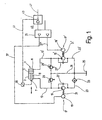
- Figure 1 shows a hydraulic double acting Piston arrangement trained actuator 1, the one has movable piston 5 in a cylinder 3, on which a piston rod 7 is attached.
- the piston 5 and the piston rod 7 are in the cylinder 3 used that two pressure chambers 9 and 11th be formed.
- the first pressure chamber 9 is via a feed line 13 connected to a pump 15, which is a drive device 17 is assigned. This includes one Electric motor 19, which is only indicated here Shaft 21 is connected to the first pump 15.
- the first pump 15 is via a supply line 23 connected to a tank 25. Parallel to the pump 15 a valve 27 is provided, on the one hand with the supply line 13 and on the other hand with the supply line 23 is connected.
- the valve 27 is here designed as a check valve, which is arranged is that with a negative pressure in the supply line 13 the hydraulic medium present in the tank 25 can be sucked in, even if the first pump 15 should not be driven.
- the second pressure chamber 11 is an identical supply system assigned: promotes via a feed line 13 ' a second pump 15 'a hydraulic medium from the Tank 25.
- the second pump 15 ' is for this purpose Supply line 23 'connected to the tank 25.
- the second pump 15 ' is a drive device 17 'assigned. It is possible to use the two pumps 15 and 15 'via a single motor, for example To drive electric motor 19. With this one
- the illustrated embodiment includes the drive device 17 'a second electric motor 19 ', the via a shaft 21' indicated here drives second pump 15 '.
- Parallel to the second Pump 15 ' is again provided with a valve, designed as a check valve 27 'and arranged so is that with a negative pressure in the supply line 13 'Hydraulic medium via the supply line 23 'are sucked out of the tank 25 can.
- the feed line 13 ' is via a pressure relief valve 29 'connected to the return line 31, which leads to tank 25.
- the hydraulic system assigned to the actuator 1 can be formed with a cooler 33, which here in the supply line 23 integrated to the first pump 15 is. It is also possible to use this cooler 33 to be installed anywhere in the hydraulic system. After all, it is also conceivable, one or several of the supply lines with cooling fins too provided to dissipate excess heat.
- the piston 5 moves within the cylinder 3 to the right. This also causes the piston rod 7 moved to the right.
- the second pump 15 ' is now operated as a motor drives the coupled electric motor 19. This now works as a generator and converts the drive energy into electrical energy and feeds them back into the electrical system of the drive, where they are used to supply the first electric motor 19 can be reused.
- one of the pumps 15, 15 ' operates as a motor and the associated electric motor 19, 19 ' as a generator what the efficiency of the drive significantly improved.
- the drive for the actuator shown in Figure 1 1 also shows a control 35, the control lines 37 and 37 'with the electric motors 19 and 19 'is connected.
- At least one sensor 39 is assigned to the actuator 1, whose output signals via a signal line 41 fed to an evaluation circuit 43 be together with the control 35 a Control circuit 45 forms.
- the evaluation circuit 43 can at least one external via a line 47 Signal are supplied via the drive can be influenced for the actuator 1.
- the sensor 39 which comprise an analog / digital converter can, is capable of various physical To detect sizes of the actuator 1, for example its location, the speed and / or acceleration of the piston 5 respectively the piston rod 7, which in the supply lines 13th and / or 13 'given pressure and / or that of the Actuator 1 applied forces. It is also conceivable that physical quantities of the actuator 1 by sensors in the feed lines 13 and 13 'respectively in the control 35 and / or the evaluation circuit 43 or the electric motors 19 and 19 'indirectly be recorded. You can also use one or more Sensors, for example current or speed sensors, in the control 35 or the electric motors 19 and 19 'can be integrated. This can, if necessary the external sensor 39 is omitted and a modular design of the drive can be realized.
- Figure 1 shows that overall a drive for an actuator 1 that can be implemented Allows two or four quadrant operation. This is both possible if the control 35 as Control circuit is realized or if this how shown in the figure, designed as a control circuit is, for example as a single-loop control loop.
- the control circuit can be continuous controllers, for example PID and / or state controller with / without observer or discontinuous controller include. It can also be constructed such that one or more of the physical quantities in parallel or be regulated sequentially.
- the means controllers with I, PI or PID behavior are preferred Regulator with integrating parts used.
- the Control circuit is by means of analog or digital technology or a combination of analog and digital technology realizable.
- the pumps 15 and 15 ' are constant pumps designed, that is, they instruct constant displacement volume. It is conceivable also, one or both of the pumps as variable displacement pumps train, with one or two displacement rooms can be realized. It is essential that also a four-quadrant drive can be implemented without any throttle valves in the supply lines 13 and 13 'to be installed.
- the drive for the actuator 1 therefore works particularly low loss. From what has been said it is also clear that the drive is very is simple and therefore inexpensive to implement, because even for a four-quadrant drive only Pumps with a constant displacement are required, that is, they can be realized relatively inexpensively Pump. All it takes is a drive for the pumps, the variable flow rates allows. This is already done with the help of one Electric motor possible, the variable speed and which is controlled via the control 35 becomes.
- the drive for the actuator 1 can So compared to the representation in the figure be further simplified, while still having a four-quadrant drive is feasible.
- the drive shown here also meets high safety requirements, because on the one hand pressure relief valves 29, 29 'and on the other hand as suction valves trained valves 27, 27 'are provided.
- the valves 27, 27 ', 29 and 29' have only a safety function and are for the normal operation of the drive is not required means they are inactive.
- a particularly simple structure can thereby be achieved that the electric motors 19 and 19 ' with the associated pumps 15 and 15 'as a unit can be trained.
- the delivery rate of the Pumping is done by adjusting the engine speed or the speed reached what with the control 35 is possible.
- This can also be built into the motor and pump Unit are integrated so that a results in a particularly compact structure. Because the actuator clamped between the two pumps 15 and 15 ' there is high rigidity.
- the areas of the piston 5, which with that in the pressure chambers 9 and 11 pressure prevailing are different sizes.
- the area of the first pressure chamber 9 results from the piston rod 7 an annular area that is smaller than the cross-sectional area of the piston 5, which with the in the second pressure chamber 11 applied pressure becomes.
- there may be proportions or area ratios of 2: 1 of the pressurized piston surfaces result.
- the delivery volumes of the pumps 15 and 15 ' this area ratio can be adjusted. Thereby can in turn the electric motors 19 and 19 ' operated at the same speed. It is however, it is readily apparent that pumps with same funding volume can be used, which operated at different drive speeds become.
- the simple Actuator drive for position and pressure control and / or for a speed and Pressure control can be designed.
- the drive for the actuator in addition to the speed-dependent Delivery regulation by the electric motors 19 or 19 ', also controlled thereby be that the displacement of the Pumping is changed. So it turns out that the Drive for the actuator 1 in a variety of ways changed and adapted to different areas of application can be.
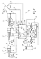
- FIG. 2 shows a drive system 51 which from several, in this case four actuators 1.1 to 1.4 exists.
- a drive system 51 is part of a machine that does different work movements in whole or in part sequential sequence performs.
- the actuators 1.1 to 1.3 are each around a hydraulic double-acting piston cylinder, as he already did in connection with figure 1 has been described. On another description is therefore waived. Only the Actuator 1.4 differs in that it is a hydraulic motor.
- the pump unit surrounded by a dashed line 53 is promoted from a tank 25.
- the pump unit 53 has two pumps 15, 15 ', those with the shaft 21 or 21 'of that Electric motor 19 or 19 'driven become.
- the two supply lines 23, 23 'of two pumps 15, 15 ' are connected to the tank 25.
- check valves 27 shown in Figure 1, 27 ', and the pressure relief valves 29, 29' are the For clarity shown as switch block 55. However, the mode of operation corresponds to that valves 27 and 29.
- the control unit 57 comprises for each actuator a control circuit 45, the a control 35 and an evaluation circuit 43 includes.
- the evaluation circuit assigned to an actuator 43 is the line 41 from supplied to the sensor 39 signal.
- FIG. 2 also allows a valve arrangement 59 recognize that in the by the two pumps 15, 15 ' coming and leading to the actuators 13 is switched.
- the valve arrangement has two hydraulic inputs 61.1 and 61.2, whereby the first input 61.1 with the pump 15 and the second input 61.2 connected to the pump 15 ' is.
- two outputs 63.1, 63.1 'to 63.4, 63.4' are provided.
- the outputs 63.1 to 63.4 are each one with the supply line 13 Actuators 1.1 to 1.4 connected, the outputs 63.1 ' to 63.4 'each with the supply line 13' of an actuator.
- the valve assembly 59 has several, in the present Embodiment preferably four switch positions in which the inputs 61.1 and 61.2 connected to predetermined outputs 63 with little loss become.
- the switching position of the valve assembly 59 can be for example via a control line 63 from the Change control unit 57.
- the pump unit 53 in the Switch position II with the actuator 1.2, in the Switch position III with the actuator 1.3 and in one Switch position IV with the hydraulic motor 1.4 connected.
- Assignments of pump unit 53 and the actuators conceivable per switch position.
- valve assembly 59 So is in the switching position of the valve assembly shown 59 the input 61.1 with the output 63.2 and the input 61.2 connected to the output 63.4.
- the valve arrangement 59 has one Exit 65 on the line 67 to the tank 25 leads.
- This output 65 is connected on the one hand with the output 63.2 'and on the other hand with the Exit 63.4 '.
- the pump 15 With the help of this circuit it is possible, the pump 15 to drive the actuator 1.2 and the pump 15 'for driving the hydraulic motor 1.4 to use.
- By using reversible Pumps 15, 15 'it is otherwise possible movement of the actuators in two directions bring about.
- valve arrangement can be 59 train so that for any desired combination of operations two actuators one switching position is provided.
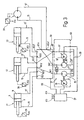
- FIG. 2 Another exemplary embodiment is shown in FIG. the basic structure of which is shown in FIG. 2 shown embodiment corresponds. On a repeated description of the same reference numerals marked parts are therefore omitted.
- valve arrangement 59 With the help of the valve arrangement 59 is in the present Embodiment another mode allows.
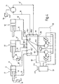
- Figure 4 shows that the inputs 61.1 and 61.2 in the switching position of the valve arrangement shown 59 connected to the output 63.3 are, while the output 63.3 'with the output 65 connected is. Both pumps thus deliver 15, 15 ' Hydraulic fluid via the feed line 13 in the Actuator 1.3 for its actuation. In the others Switch positions of the valve arrangement 59 can be then actuators 1.1, 1.2 and 1.4 with the two Connect pumps 15, 15 '.
Landscapes
- Engineering & Computer Science (AREA)
- Physics & Mathematics (AREA)
- Fluid Mechanics (AREA)
- Mechanical Engineering (AREA)
- General Engineering & Computer Science (AREA)
- Fluid-Pressure Circuits (AREA)
Description
- Figur 1
- ein Prinzipschaltbild des Antriebs;
- Figur 2
- ein Prinzipschaltbild eines Antriebssystems mit mehreren Aktuatoren;
- Figur 3
- ein zweites Ausführungsbeispiel eines Antriebssystems mit mehreren Aktuatoren, und
- Figur 4
- ein drittes Antriebssystem mit mehreren Aktuatoren.
Claims (19)
- Antriebssystem mit zumindest zwei hydraulischen Aktuatoren (1.1, 1.2, 1.3, 1.4), die mittels zumindest einer ersten Pumpe (15) und zumindest einer weiteren parallel zur ersten Pumpe (15) angeordneten zweiten Pumpe (15') mit Hydraulikmedium versorgt werden, wobei die Pumpen (15,15') bidirektional drehzahlgeregelt sind, und einer Ventilanordnung (59) mit je einem Eingang (61.1,61.2) pro Pumpe (15,15'), wobei jeweils einer der Eingänge (61.1,61.2) mit einer der Pumpen (15,15') verbunden ist, und mit einer Anzahl von Ausgängen (63.1,63.1',...63.4,63.4'), die mit den Aktuatoren (1.1...1.4) verbunden sind, dadurch gekennzeichnet, dass die Ventilanordnung (59) mehrere Schaltstellungen aufweist, in denen die Eingänge (61) mit einem oder mehreren vorbestimmten Ausgängen (63) verbindbar sind, wobei in zumindest einer Schaltstellung der Ventilanordnung (59) wenigstens einer der zumindest zwei Aktuatoren (1.1,1.2,1.3,1.4) von den Pumpen (15,15') trennbar ist.
- Antriebssystem nach Anspruch 1, dadurch gekennzeichnet, daß in einer Schaltstellung der Ventilanordnung (59) der erste Eingang (61.1) dem einen Ausgang (63.1) und der zweite Eingang (61.2) dem anderen Ausgang (63.1') eines Aktuators (1.1) zugeordnet sind.
- Antriebssystem nach Anspruch 1 oder 2, dadurch gekennzeichnet, daß die Ventilanordnung (59) so ausgebildet ist, daß in einer Schaltstellung die beiden Pumpen (15,15') mit unterschiedlichen Aktuatoren (1) verbindbar sind.
- Antriebssystem nach einem der vorhergehenden Ansprüche, dadurch gekennzeichnet, daß die Ventilanordnung (59) so ausgebildet ist, daß in einer Schaltstellung die beiden Pumpen (15,15') gemeinsam mit einem Ausgang (63) zur Versorgung eines Aktuators (1) verbindbar sind.
- Antriebssystem nach einem der vorhergehenden Ansprüche, dadurch gekennzeichnet, daß die Ventilanordnung (59) mit Sitzventilen ausgeführt ist, um die Aktuatoren bei Bedarf leckagefrei festzusetzen.
- Antriebssystem nach einem der vorhergehenden Ansprüche, dadurch gekennzeichnet, daß die Ventilanordnung (59) für einfachbetätigte Aktuatoren mit Gegenhalteventilen ausgeführt ist.
- Antriebssystem nach Anspruch 5 oder 6, dadurch gekennzeichnet, daß wenigstens eine Pumpe (15,15') ein konstantes Verdrängungsvolumen aufweist und/oder wenigstens eine Pumpe (15,15') als Verstellpumpe ausgebildet ist.
- Antriebssystem nach einem der vorhergehenden Ansprüche, dadurch gekennzeichnet, daß beiden Pumpen (15,15') eine separate Antriebseinrichtung (Elektromotor (19,19')) zugeordnet ist.
- Antriebssystem nach einem der vorhergehenden Ansprüche, dadurch gekennzeichnet, daß die Ansteuerung (57,35) als Steuerschaltung ausgelegt ist.
- Antriebssystem nach einem der vorhergehenden Ansprüche, dadurch gekennzeichnet, daß die Ansteuerung (57,35) als Regelschaltung (45) ausgelegt ist und mindestens einen Sensor (39) umfaßt.
- Antriebssystem nach Anspruch 10, dadurch gekennzeichnet, daß mindestens ein Sensor (39) dem Aktuator (1) zugeordnet ist.
- Antriebssystem nach Anspruch 10 oder 11, dadurch gekennzeichnet, daß der Sensor (39) Lage, Geschwindigkeit und/oder Beschleunigung des Aktuators (1) und/oder den auf den Aktuator (1) wirkenden Druck und/oder die von dem Aktuator (1) ausgeübten Kräfte erfaßt.
- Antriebssystem nach einem der Ansprüche 10 bis 12, dadurch gekennzeichnet, daß die Regelschaltung (45) kontinuierliche Regler und/oder Zustandsregler mit/ohne Beobachter oder diskontinuierliche Regler umfaßt.
- Antriebssystem nach einem oder mehreren der vorhergehenden Ansprüche, dadurch gekennzeichnet, daß die Regelschaltung (45) mittels Analogund/oder Digitaltechnik realisierbar ist.
- Antriebssystem nach einem oder mehreren der vorhergehenden Ansprüche, gekennzeichnet durch eine Regelschaltung (45), mit der eine parallele oder sequentielle Regelung von mindestens einer erfaßten physikalischen Größe realisierbar ist.
- Antriebssystem nach einem der vorhergehenden Ansprüche, dadurch gekennzeichnet, daß die Antriebseinrichtung (17,17') und die Ansteuerung (57,35) als Einheit ausgebildet sind.
- Antriebssystem nach einem der vorhergehenden Ansprüche, dadurch gekennzeichnet, daß die Antriebseinrichtung (17,17') mindestens einen Elektromotor (19,19') mit variabler Drehzahl für beide Drehrichtungen umfaßt.
- Antriebssystem nach einem der vorhergehenden Ansprüche, dadurch gekennzeichnet, daß die Ansteuerungen (35), die Steuerung der Ventilanordnung (59) und die Regelschaltungen (45) zu einer Steuerungseinheit (57) zusammengefaßt sind.
- Antriebssystem nach einem der vorhergehenden Ansprüche, dadurch gekennzeichnet, daß die Ansteuerungen (35), die Regelschaltungen (45) oder die Steuerungseinheit (57) über ein Bussystem für den Datenaustausch verfügen.
Priority Applications (1)
| Application Number | Priority Date | Filing Date | Title |
|---|---|---|---|
| EP02023249A EP1288507B1 (de) | 1996-01-10 | 1996-12-21 | Verlustarmer Antrieb für einen hydraulischen Aktuator |
Applications Claiming Priority (5)
| Application Number | Priority Date | Filing Date | Title |
|---|---|---|---|
| DE19600650 | 1996-01-10 | ||
| DE19600650A DE19600650C2 (de) | 1996-01-10 | 1996-01-10 | Antrieb für einen hydraulischen doppelwirkenden Aktuator |
| DE19642163A DE19642163A1 (de) | 1996-01-10 | 1996-10-12 | Verlustarmer Antrieb für mehrere hydraulische Aktuatoren |
| DE19642163 | 1996-10-12 | ||
| PCT/EP1996/005801 WO1997025532A1 (de) | 1996-01-10 | 1996-12-21 | Verlustarmer antrieb für mehrere hydraulische aktuatoren |
Related Child Applications (1)
| Application Number | Title | Priority Date | Filing Date |
|---|---|---|---|
| EP02023249A Division EP1288507B1 (de) | 1996-01-10 | 1996-12-21 | Verlustarmer Antrieb für einen hydraulischen Aktuator |
Publications (2)
| Publication Number | Publication Date |
|---|---|
| EP0873475A1 EP0873475A1 (de) | 1998-10-28 |
| EP0873475B1 true EP0873475B1 (de) | 2003-10-15 |
Family
ID=26021974
Family Applications (1)
| Application Number | Title | Priority Date | Filing Date |
|---|---|---|---|
| EP96944055A Expired - Lifetime EP0873475B1 (de) | 1996-01-10 | 1996-12-21 | Verlustarmer antrieb für mehrere hydraulische aktuatoren |
Country Status (6)
| Country | Link |
|---|---|
| US (1) | US6205780B1 (de) |
| EP (1) | EP0873475B1 (de) |
| AU (1) | AU1377997A (de) |
| DE (1) | DE59611324D1 (de) |
| TW (1) | TW401486B (de) |
| WO (1) | WO1997025532A1 (de) |
Cited By (4)
| Publication number | Priority date | Publication date | Assignee | Title |
|---|---|---|---|---|
| DE102010024025A1 (de) * | 2010-06-16 | 2011-12-22 | Hydac Fluidtechnik Gmbh | Hydraulikaggregat |
| DE102010034187A1 (de) * | 2010-08-12 | 2012-02-16 | Lukas Hydraulik Gmbh | Steuereinrichtung für erstes und zweites Arbeitsgerät |
| DE102015218731A1 (de) | 2014-10-01 | 2016-04-07 | Schaeffler Technologies AG & Co. KG | Fluidische Betätigungsanordnung |
| CN107013519A (zh) * | 2016-01-22 | 2017-08-04 | 恩格尔奥地利有限公司 | 用于成型机的液压装置以及具有液压装置的成型机 |
Families Citing this family (25)
| Publication number | Priority date | Publication date | Assignee | Title |
|---|---|---|---|---|
| ITMO20050220A1 (it) * | 2005-08-31 | 2007-03-01 | Studio Tecnico 6M Srl | Dispositivo fluidodinamico |
| WO2007114339A1 (ja) * | 2006-03-30 | 2007-10-11 | Yuken Kogyo Co., Ltd. | 油圧供給装置及びそれを用いた油圧アクチュエータ装置の制御方法 |
| US20090090102A1 (en) * | 2006-05-03 | 2009-04-09 | Wilfred Busse | Method of reducing the load of one or more engines in a large hydraulic excavator |
| GB0614534D0 (en) * | 2006-07-21 | 2006-08-30 | Artemis Intelligent Power Ltd | Fluid power distribution and control system |
| SI1911979T1 (sl) | 2006-10-11 | 2011-12-30 | Studio Tecnico 6M Srl | Dinamična fluidna naprava |
| US8206134B2 (en) * | 2008-06-02 | 2012-06-26 | Maradyne Corporation | Combined power pack unit |
| DE102008039011B4 (de) * | 2008-08-21 | 2020-01-16 | MAE Maschinen- u. Apparatebau Götzen GmbH | Druckspeicherlose hydraulische Antriebsanordnung sowie Verfahren zum druckspeicherlosen hydraulischen Antreiben eines Verbrauchers |
| JP2012523531A (ja) * | 2009-04-08 | 2012-10-04 | パーカー・ハニフィン・コーポレーション | 複数のポンプを有する油圧回路 |
| US20110056192A1 (en) * | 2009-09-10 | 2011-03-10 | Robert Weber | Technique for controlling pumps in a hydraulic system |
| US9032724B2 (en) | 2010-06-21 | 2015-05-19 | Husco International Inc. | Command based method for allocating fluid flow from a plurality of pumps to multiple hydraulic functions |
| DE102011000473B4 (de) | 2011-02-02 | 2017-07-13 | Langenstein & Schemann Gmbh | Pressmaschine und Verfahren zum Pressen von Werkstücken |
| US9644761B2 (en) | 2011-09-30 | 2017-05-09 | General Electric Company | Desalination system with energy recovery and related pumps, valves and controller |
| US9387440B2 (en) | 2011-09-30 | 2016-07-12 | General Electric Company | Desalination system with energy recovery and related pumps, valves and controller |
| EP2594807A1 (de) * | 2011-11-16 | 2013-05-22 | Palfinger Platforms GmbH | Hydrauliksystem mit zumindest einer, insbesondere als Pumpe ausgebildeten, Antriebsmaschine |
| CN104582910B (zh) | 2012-08-27 | 2016-11-16 | 埃克苏仿生公司 | 液压致动器系统 |
| EP2712688B1 (de) | 2012-09-28 | 2020-12-02 | Siemens Aktiengesellschaft | Ziehkissenantrieb und Betriebsverfahren eines Ziehkissenantriebes |
| US9638179B2 (en) | 2012-12-04 | 2017-05-02 | General Electric Company | Hydraulic control system for a reverse osmosis hydraulic pump |
| US9897080B2 (en) | 2012-12-04 | 2018-02-20 | General Electric Company | Rotary control valve for reverse osmosis feed water pump with energy recovery |
| FR3005703B1 (fr) * | 2013-05-14 | 2016-08-19 | Machine Smart | Systeme hydraulique a controle electronique de pression et de debit |
| EP2905480B1 (de) * | 2014-02-07 | 2016-10-19 | Caterpillar Global Mining LLC | Hydraulisches Steuersystem und -verfahren |
| EP2990664A1 (de) * | 2014-08-27 | 2016-03-02 | Siemens Aktiengesellschaft | Hydraulikanlage |
| KR20190050701A (ko) * | 2017-11-03 | 2019-05-13 | 보르그워너 인코퍼레이티드 | 4-위치 주 압력 조절기를 갖는 유압 제어 시스템 |
| CN108412826B (zh) * | 2018-04-26 | 2023-07-25 | 福建工程学院 | 一种双泵并联驱动的电静液作动器及其控制方法 |
| CN112739914B (zh) * | 2018-08-21 | 2024-02-20 | 西门子能源美国公司 | 具有用于每个致动方向的不同的泵的双作用液压致动器 |
| DK3670929T3 (da) * | 2018-12-20 | 2022-09-12 | Siemens Gamesa Renewable Energy As | Hydraulisk pumpeindretning |
Family Cites Families (17)
| Publication number | Priority date | Publication date | Assignee | Title |
|---|---|---|---|---|
| FR2203438A5 (de) * | 1972-10-17 | 1974-05-10 | Poclain Sa | |
| GB1459183A (en) * | 1972-12-22 | 1976-12-22 | Non Impact Surfaces Ltd | Road planing machines |
| US4008571A (en) * | 1976-03-31 | 1977-02-22 | Towmotor Corporation | Hydraulic system for electric lift trucks |
| US4070857A (en) * | 1976-12-22 | 1978-01-31 | Towmotor Corporation | Hydraulic priority circuit |
| NL7805880A (nl) * | 1978-05-30 | 1979-12-04 | Bos Kalis Westminster | Hydraulische gelijkloopaandrijfinrichting. |
| SE411566B (sv) | 1978-06-26 | 1980-01-14 | Akermans Verkstad Ab | Ventilblock for hydraulisk grevmaskiner |
| US4378675A (en) * | 1981-01-14 | 1983-04-05 | Mobil Oil Corporation | Hydraulic pump interlock system |
| JPS5817202A (ja) * | 1981-07-24 | 1983-02-01 | Hitachi Constr Mach Co Ltd | 油圧回路の制御方法 |
| EP0103727A1 (de) | 1982-09-02 | 1984-03-28 | Inventio Ag | Gleichlaufregelungseinrichtung für den elektrohydraulischen Antrieb einer Abkantpresse |
| US4635439A (en) * | 1985-04-11 | 1987-01-13 | Caterpillar Industrial Inc. | Fluid operated system control |
| SE461391B (sv) | 1987-10-28 | 1990-02-12 | Bt Ind Ab | Hydraulisk lyftanordning |
| DE4030950A1 (de) * | 1990-09-29 | 1992-04-02 | Bosch Gmbh Robert | Hydraulische steuereinrichtung |
| CZ279137B6 (cs) * | 1991-12-04 | 1995-01-18 | František Ing. Krňávek | Zařízení pro rekuperaci polohové energie praco vního zařízení stavebního, nebo zemního stroje |
| CA2112711C (en) | 1993-12-31 | 1996-09-17 | Minoru Saruwatari | Hydraulic actuating system for a fluid transfer apparatus |
| DE59503395D1 (de) | 1994-01-28 | 1998-10-08 | Pleiger Maschf Paul | Vorrichtung zum Betreiben von hydraulisch betätigten Armaturen |
| GB9422561D0 (en) * | 1994-11-09 | 1995-01-04 | Funnell Nicholas J | Variable speed electro/hydraulic drive system for animal exercises |
| JPH08133688A (ja) * | 1994-11-10 | 1996-05-28 | Ebara Corp | 可動床の昇降装置 |
-
1996
- 1996-12-21 AU AU13779/97A patent/AU1377997A/en not_active Abandoned
- 1996-12-21 US US09/101,502 patent/US6205780B1/en not_active Expired - Lifetime
- 1996-12-21 DE DE59611324T patent/DE59611324D1/de not_active Expired - Lifetime
- 1996-12-21 WO PCT/EP1996/005801 patent/WO1997025532A1/de not_active Ceased
- 1996-12-21 EP EP96944055A patent/EP0873475B1/de not_active Expired - Lifetime
-
1997
- 1997-01-10 TW TW086100222A patent/TW401486B/zh not_active IP Right Cessation
Cited By (7)
| Publication number | Priority date | Publication date | Assignee | Title |
|---|---|---|---|---|
| DE102010024025A1 (de) * | 2010-06-16 | 2011-12-22 | Hydac Fluidtechnik Gmbh | Hydraulikaggregat |
| EP2397703A3 (de) * | 2010-06-16 | 2014-06-18 | Hydac Fluidtechnik GmbH | Hydraulikaggregat |
| DE102010034187A1 (de) * | 2010-08-12 | 2012-02-16 | Lukas Hydraulik Gmbh | Steuereinrichtung für erstes und zweites Arbeitsgerät |
| DE102015218731A1 (de) | 2014-10-01 | 2016-04-07 | Schaeffler Technologies AG & Co. KG | Fluidische Betätigungsanordnung |
| CN107013519A (zh) * | 2016-01-22 | 2017-08-04 | 恩格尔奥地利有限公司 | 用于成型机的液压装置以及具有液压装置的成型机 |
| DE102017000523B4 (de) * | 2016-01-22 | 2018-05-09 | Engel Austria Gmbh | Hydraulikvorrichtung für eine Formgebungsmaschine |
| CN107013519B (zh) * | 2016-01-22 | 2019-05-07 | 恩格尔奥地利有限公司 | 用于成型机的液压装置以及具有液压装置的成型机 |
Also Published As
| Publication number | Publication date |
|---|---|
| EP0873475A1 (de) | 1998-10-28 |
| WO1997025532A1 (de) | 1997-07-17 |
| US6205780B1 (en) | 2001-03-27 |
| TW401486B (en) | 2000-08-11 |
| AU1377997A (en) | 1997-08-01 |
| DE59611324D1 (de) | 2006-04-06 |
Similar Documents
| Publication | Publication Date | Title |
|---|---|---|
| EP0873475A1 (de) | Verlustarmer antrieb für mehrere hydraulische aktuatoren | |
| DE69735495T2 (de) | Elektrohydraulisches system und vorrichtung mit zweiseitig gerichteter elektromotor-/hydraulikpumpen-einheit | |
| EP1288507B1 (de) | Verlustarmer Antrieb für einen hydraulischen Aktuator | |
| DE1916224C3 (de) | Hydrostatisches Getriebe | |
| EP1588057A1 (de) | Hydrauliksystem für verdrängergesteuerte linearantriebe | |
| DE3307570A1 (de) | Hydraulisches steuersystem fuer eine servoantriebseinheit | |
| DE3716200A1 (de) | Steuer- und regeleinrichtung fuer ein hydrostatisches antriebsaggregat und verfahren zum betreiben eines solchen | |
| DE1956835A1 (de) | Kraftuebertragungsvorrichtung | |
| DE3347000A1 (de) | Elektrohydraulische einrichtung zur steuerung eines doppeltwirkenden hydromotors | |
| DE3640082A1 (de) | Elektrohydrostatischer aktuator | |
| EP0561185B1 (de) | Hydraulische Schiebersteuerung für Arbeitszylinder mit ungleichen Kolbengeschwindigkeiten | |
| EP0305761A2 (de) | Sekundärgeregeltes hydrostatisches Getriebe mit offenem Kreislauf | |
| WO2019076391A1 (de) | Wechselschaltende hydraulikeinheit | |
| DE1503350B2 (de) | Einrichtung zur regelung eines mit druckfluessigkeit beaufschlagten, eine maschine antreibenden axialkolbenmotors | |
| DE19642163A1 (de) | Verlustarmer Antrieb für mehrere hydraulische Aktuatoren | |
| DE3122369A1 (de) | Servolenkung | |
| DE10138026A1 (de) | Verfahren zum Steuern des Bewegungsablaufs von Pneumatikantrieben, sowie Pneumatikantriebssteuerung | |
| DE2751663A1 (de) | Hydrostatische kraftuebertragungsanordnung mit belastungsausgleich | |
| DD207517B1 (de) | Einrichtung zum positionieren an druckmaschinen | |
| DE10159403A1 (de) | Wirkmaschine | |
| EP0707147B1 (de) | Steuervorrichtung für eine hydrostatische Maschine | |
| DE2322998B2 (de) | Hydraulische Stelleinrichtung, insbesondere für eine Lenkung | |
| EP0229330A2 (de) | Schwenkwerk mit zwei separaten Zylinder-Kurbeltrieben als Antrieb | |
| DE3311042A1 (de) | Steuersystem fuer eine hydraulikmotorantriebseinheit | |
| DE3316119A1 (de) | Regelsystem fuer eine kraftantriebseinheit |
Legal Events
| Date | Code | Title | Description |
|---|---|---|---|
| PUAI | Public reference made under article 153(3) epc to a published international application that has entered the european phase |
Free format text: ORIGINAL CODE: 0009012 |
|
| 17P | Request for examination filed |
Effective date: 19980810 |
|
| AK | Designated contracting states |
Kind code of ref document: A1 Designated state(s): DE FR GB IT NL |
|
| 17Q | First examination report despatched |
Effective date: 20010709 |
|
| GRAH | Despatch of communication of intention to grant a patent |
Free format text: ORIGINAL CODE: EPIDOS IGRA |
|
| RAP1 | Party data changed (applicant data changed or rights of an application transferred) |
Owner name: EATON FLUID POWER GMBH |
|
| GRAS | Grant fee paid |
Free format text: ORIGINAL CODE: EPIDOSNIGR3 |
|
| GRAA | (expected) grant |
Free format text: ORIGINAL CODE: 0009210 |
|
| AK | Designated contracting states |
Kind code of ref document: B1 Designated state(s): DE FR GB IT NL |
|
| REG | Reference to a national code |
Ref country code: GB Ref legal event code: FG4D Free format text: NOT ENGLISH |
|
| REF | Corresponds to: |
Ref document number: 59610776 Country of ref document: DE Date of ref document: 20031120 Kind code of ref document: P |
|
| GBV | Gb: ep patent (uk) treated as always having been void in accordance with gb section 77(7)/1977 [no translation filed] |
Effective date: 20031015 |
|
| ET | Fr: translation filed | ||
| PLBE | No opposition filed within time limit |
Free format text: ORIGINAL CODE: 0009261 |
|
| STAA | Information on the status of an ep patent application or granted ep patent |
Free format text: STATUS: NO OPPOSITION FILED WITHIN TIME LIMIT |
|
| 26N | No opposition filed |
Effective date: 20040716 |
|
| REG | Reference to a national code |
Ref country code: GB Ref legal event code: 710B Free format text: EXTENSION APPLICATION: APPLICATION FOR EXTENSION OF THE PERIOD(S) PRESCRIBED BY RULE(S) SCHEDULE 4 PARA 2 FILED ON 20050408. |
|
| GBT | Gb: translation of ep patent filed (gb section 77(6)(a)/1977) |
Effective date: 20051209 |
|
| REG | Reference to a national code |
Ref country code: GB Ref legal event code: 9110 Free format text: EXTENSION ALLOWED: PERIOD(S) PRESCRIBED BY RULE(S) SCHEDULE 4 PARA 2 EXTENDED UNDER RULE 110(6) IN ACCORDANCE WITH THE DECISION OF THE COMPTROLLER DATED 20051025. THE PATENT/APPLICATION IS REINSTATED SUBJECT TO SPECIAL TERMS FOR THIRD PARTY INTERESTS. |
|
| PGFP | Annual fee paid to national office [announced via postgrant information from national office to epo] |
Ref country code: NL Payment date: 20081111 Year of fee payment: 13 |
|
| REG | Reference to a national code |
Ref country code: NL Ref legal event code: V1 Effective date: 20100701 |
|
| PG25 | Lapsed in a contracting state [announced via postgrant information from national office to epo] |
Ref country code: NL Free format text: LAPSE BECAUSE OF NON-PAYMENT OF DUE FEES Effective date: 20100701 |
|
| REG | Reference to a national code |
Ref country code: FR Ref legal event code: PLFP Year of fee payment: 20 |
|
| PGFP | Annual fee paid to national office [announced via postgrant information from national office to epo] |
Ref country code: GB Payment date: 20151125 Year of fee payment: 20 |
|
| PGFP | Annual fee paid to national office [announced via postgrant information from national office to epo] |
Ref country code: FR Payment date: 20151124 Year of fee payment: 20 |
|
| PGFP | Annual fee paid to national office [announced via postgrant information from national office to epo] |
Ref country code: DE Payment date: 20151230 Year of fee payment: 20 Ref country code: IT Payment date: 20151210 Year of fee payment: 20 |
|
| REG | Reference to a national code |
Ref country code: DE Ref legal event code: R071 Ref document number: 59610776 Country of ref document: DE |
|
| REG | Reference to a national code |
Ref country code: GB Ref legal event code: PE20 Expiry date: 20161220 |
|
| PG25 | Lapsed in a contracting state [announced via postgrant information from national office to epo] |
Ref country code: GB Free format text: LAPSE BECAUSE OF EXPIRATION OF PROTECTION Effective date: 20161220 |