EP0872563A1 - Dispositif et procédé de traitement thermique - Google Patents
Dispositif et procédé de traitement thermique Download PDFInfo
- Publication number
- EP0872563A1 EP0872563A1 EP98400761A EP98400761A EP0872563A1 EP 0872563 A1 EP0872563 A1 EP 0872563A1 EP 98400761 A EP98400761 A EP 98400761A EP 98400761 A EP98400761 A EP 98400761A EP 0872563 A1 EP0872563 A1 EP 0872563A1
- Authority
- EP
- European Patent Office
- Prior art keywords
- nozzle
- distribution
- sleeve
- protective gas
- cooling
- Prior art date
- Legal status (The legal status is an assumption and is not a legal conclusion. Google has not performed a legal analysis and makes no representation as to the accuracy of the status listed.)
- Granted
Links
- 238000000034 method Methods 0.000 title claims abstract description 35
- 239000000463 material Substances 0.000 claims abstract description 62
- 238000001816 cooling Methods 0.000 claims abstract description 39
- 238000009826 distribution Methods 0.000 claims abstract description 37
- 230000001681 protective effect Effects 0.000 claims abstract description 34
- 238000010438 heat treatment Methods 0.000 claims abstract description 24
- 239000003507 refrigerant Substances 0.000 claims abstract description 11
- 230000008569 process Effects 0.000 claims abstract description 10
- 239000012809 cooling fluid Substances 0.000 claims abstract description 8
- 239000007789 gas Substances 0.000 claims description 56
- 238000000576 coating method Methods 0.000 claims description 33
- XKRFYHLGVUSROY-UHFFFAOYSA-N Argon Chemical compound [Ar] XKRFYHLGVUSROY-UHFFFAOYSA-N 0.000 claims description 32
- IJGRMHOSHXDMSA-UHFFFAOYSA-N Atomic nitrogen Chemical compound N#N IJGRMHOSHXDMSA-UHFFFAOYSA-N 0.000 claims description 31
- 239000003570 air Substances 0.000 claims description 20
- 229910052786 argon Inorganic materials 0.000 claims description 16
- 229910052757 nitrogen Inorganic materials 0.000 claims description 14
- 239000002245 particle Substances 0.000 claims description 13
- 239000000203 mixture Substances 0.000 claims description 8
- 239000012159 carrier gas Substances 0.000 claims description 7
- 229910052751 metal Inorganic materials 0.000 claims description 7
- 239000002184 metal Substances 0.000 claims description 7
- 150000002739 metals Chemical class 0.000 claims description 7
- VYPSYNLAJGMNEJ-UHFFFAOYSA-N Silicium dioxide Chemical compound O=[Si]=O VYPSYNLAJGMNEJ-UHFFFAOYSA-N 0.000 claims description 6
- 239000000919 ceramic Substances 0.000 claims description 5
- 239000004033 plastic Substances 0.000 claims description 4
- 229920003023 plastic Polymers 0.000 claims description 4
- 238000011144 upstream manufacturing Methods 0.000 claims description 4
- 229910001092 metal group alloy Inorganic materials 0.000 claims description 3
- 229920000642 polymer Polymers 0.000 claims description 3
- 239000000377 silicon dioxide Substances 0.000 claims description 3
- 239000001307 helium Substances 0.000 claims description 2
- 229910052734 helium Inorganic materials 0.000 claims description 2
- SWQJXJOGLNCZEY-UHFFFAOYSA-N helium atom Chemical compound [He] SWQJXJOGLNCZEY-UHFFFAOYSA-N 0.000 claims description 2
- 229910052500 inorganic mineral Inorganic materials 0.000 claims description 2
- 229910044991 metal oxide Inorganic materials 0.000 claims description 2
- 150000004706 metal oxides Chemical class 0.000 claims description 2
- 239000011707 mineral Substances 0.000 claims description 2
- 239000012768 molten material Substances 0.000 claims description 2
- 229910045601 alloy Inorganic materials 0.000 claims 1
- 239000000956 alloy Substances 0.000 claims 1
- 239000012530 fluid Substances 0.000 abstract description 4
- 239000011248 coating agent Substances 0.000 description 28
- 239000000758 substrate Substances 0.000 description 27
- CURLTUGMZLYLDI-UHFFFAOYSA-N Carbon dioxide Chemical compound O=C=O CURLTUGMZLYLDI-UHFFFAOYSA-N 0.000 description 26
- 239000007788 liquid Substances 0.000 description 14
- 239000011247 coating layer Substances 0.000 description 13
- 229910002092 carbon dioxide Inorganic materials 0.000 description 12
- 239000001569 carbon dioxide Substances 0.000 description 11
- 238000009833 condensation Methods 0.000 description 11
- 230000005494 condensation Effects 0.000 description 11
- 239000002826 coolant Substances 0.000 description 11
- 239000010410 layer Substances 0.000 description 11
- XLYOFNOQVPJJNP-UHFFFAOYSA-N water Chemical compound O XLYOFNOQVPJJNP-UHFFFAOYSA-N 0.000 description 7
- 230000008021 deposition Effects 0.000 description 6
- 230000004907 flux Effects 0.000 description 6
- 239000007921 spray Substances 0.000 description 6
- 238000004519 manufacturing process Methods 0.000 description 5
- PXHVJJICTQNCMI-UHFFFAOYSA-N Nickel Chemical compound [Ni] PXHVJJICTQNCMI-UHFFFAOYSA-N 0.000 description 4
- 230000004927 fusion Effects 0.000 description 4
- 229910052782 aluminium Inorganic materials 0.000 description 3
- XAGFODPZIPBFFR-UHFFFAOYSA-N aluminium Chemical compound [Al] XAGFODPZIPBFFR-UHFFFAOYSA-N 0.000 description 3
- 230000004888 barrier function Effects 0.000 description 3
- 238000003860 storage Methods 0.000 description 3
- 229910000838 Al alloy Inorganic materials 0.000 description 2
- OKTJSMMVPCPJKN-UHFFFAOYSA-N Carbon Chemical compound [C] OKTJSMMVPCPJKN-UHFFFAOYSA-N 0.000 description 2
- VYZAMTAEIAYCRO-UHFFFAOYSA-N Chromium Chemical compound [Cr] VYZAMTAEIAYCRO-UHFFFAOYSA-N 0.000 description 2
- RYGMFSIKBFXOCR-UHFFFAOYSA-N Copper Chemical compound [Cu] RYGMFSIKBFXOCR-UHFFFAOYSA-N 0.000 description 2
- GWEVSGVZZGPLCZ-UHFFFAOYSA-N Titan oxide Chemical compound O=[Ti]=O GWEVSGVZZGPLCZ-UHFFFAOYSA-N 0.000 description 2
- MCMNRKCIXSYSNV-UHFFFAOYSA-N Zirconium dioxide Chemical compound O=[Zr]=O MCMNRKCIXSYSNV-UHFFFAOYSA-N 0.000 description 2
- AZDRQVAHHNSJOQ-UHFFFAOYSA-N alumane Chemical group [AlH3] AZDRQVAHHNSJOQ-UHFFFAOYSA-N 0.000 description 2
- QVGXLLKOCUKJST-UHFFFAOYSA-N atomic oxygen Chemical compound [O] QVGXLLKOCUKJST-UHFFFAOYSA-N 0.000 description 2
- 230000015572 biosynthetic process Effects 0.000 description 2
- 229910052799 carbon Inorganic materials 0.000 description 2
- 235000011089 carbon dioxide Nutrition 0.000 description 2
- 239000002131 composite material Substances 0.000 description 2
- 229910052802 copper Inorganic materials 0.000 description 2
- 239000010949 copper Substances 0.000 description 2
- 230000032798 delamination Effects 0.000 description 2
- 230000002349 favourable effect Effects 0.000 description 2
- 238000007749 high velocity oxygen fuel spraying Methods 0.000 description 2
- 238000009434 installation Methods 0.000 description 2
- 229910052759 nickel Inorganic materials 0.000 description 2
- 230000003647 oxidation Effects 0.000 description 2
- 238000007254 oxidation reaction Methods 0.000 description 2
- 239000001301 oxygen Substances 0.000 description 2
- 229910052760 oxygen Inorganic materials 0.000 description 2
- 230000010349 pulsation Effects 0.000 description 2
- 238000010791 quenching Methods 0.000 description 2
- 230000000171 quenching effect Effects 0.000 description 2
- 238000005507 spraying Methods 0.000 description 2
- 238000010408 sweeping Methods 0.000 description 2
- 238000007751 thermal spraying Methods 0.000 description 2
- 241001573881 Corolla Species 0.000 description 1
- ZOKXTWBITQBERF-UHFFFAOYSA-N Molybdenum Chemical compound [Mo] ZOKXTWBITQBERF-UHFFFAOYSA-N 0.000 description 1
- 229910000831 Steel Inorganic materials 0.000 description 1
- 230000006978 adaptation Effects 0.000 description 1
- -1 aluminum Chemical class 0.000 description 1
- 239000012080 ambient air Substances 0.000 description 1
- 238000004873 anchoring Methods 0.000 description 1
- 238000000889 atomisation Methods 0.000 description 1
- 230000015556 catabolic process Effects 0.000 description 1
- 238000005524 ceramic coating Methods 0.000 description 1
- 238000006243 chemical reaction Methods 0.000 description 1
- 229910052804 chromium Inorganic materials 0.000 description 1
- 239000011651 chromium Substances 0.000 description 1
- 239000010941 cobalt Substances 0.000 description 1
- 229910017052 cobalt Inorganic materials 0.000 description 1
- GUTLYIVDDKVIGB-UHFFFAOYSA-N cobalt atom Chemical compound [Co] GUTLYIVDDKVIGB-UHFFFAOYSA-N 0.000 description 1
- 238000002485 combustion reaction Methods 0.000 description 1
- 230000006835 compression Effects 0.000 description 1
- 238000007906 compression Methods 0.000 description 1
- 238000011109 contamination Methods 0.000 description 1
- 238000005520 cutting process Methods 0.000 description 1
- 238000006731 degradation reaction Methods 0.000 description 1
- 230000001419 dependent effect Effects 0.000 description 1
- 238000009792 diffusion process Methods 0.000 description 1
- 229910001873 dinitrogen Inorganic materials 0.000 description 1
- 229940082150 encore Drugs 0.000 description 1
- 239000000945 filler Substances 0.000 description 1
- 238000001914 filtration Methods 0.000 description 1
- 239000000446 fuel Substances 0.000 description 1
- 238000009413 insulation Methods 0.000 description 1
- 230000002427 irreversible effect Effects 0.000 description 1
- 238000003698 laser cutting Methods 0.000 description 1
- 238000002844 melting Methods 0.000 description 1
- 230000008018 melting Effects 0.000 description 1
- 239000003607 modifier Substances 0.000 description 1
- 229910052750 molybdenum Inorganic materials 0.000 description 1
- 239000011733 molybdenum Substances 0.000 description 1
- 238000005121 nitriding Methods 0.000 description 1
- 239000011368 organic material Substances 0.000 description 1
- 238000013021 overheating Methods 0.000 description 1
- 239000000123 paper Substances 0.000 description 1
- 230000003071 parasitic effect Effects 0.000 description 1
- 235000011837 pasties Nutrition 0.000 description 1
- 238000007750 plasma spraying Methods 0.000 description 1
- 238000012545 processing Methods 0.000 description 1
- 239000011253 protective coating Substances 0.000 description 1
- 238000011160 research Methods 0.000 description 1
- 239000011347 resin Substances 0.000 description 1
- 229920005989 resin Polymers 0.000 description 1
- 238000007789 sealing Methods 0.000 description 1
- 238000002791 soaking Methods 0.000 description 1
- 239000008247 solid mixture Substances 0.000 description 1
- 238000003892 spreading Methods 0.000 description 1
- 230000007480 spreading Effects 0.000 description 1
- 230000000087 stabilizing effect Effects 0.000 description 1
- 239000010959 steel Substances 0.000 description 1
- 238000012360 testing method Methods 0.000 description 1
- 239000004408 titanium dioxide Substances 0.000 description 1
- 238000012546 transfer Methods 0.000 description 1
- UONOETXJSWQNOL-UHFFFAOYSA-N tungsten carbide Chemical compound [W+]#[C-] UONOETXJSWQNOL-UHFFFAOYSA-N 0.000 description 1
- 238000010792 warming Methods 0.000 description 1
- 239000002699 waste material Substances 0.000 description 1
- 239000002023 wood Substances 0.000 description 1
Images


Classifications
-
- F—MECHANICAL ENGINEERING; LIGHTING; HEATING; WEAPONS; BLASTING
- F25—REFRIGERATION OR COOLING; COMBINED HEATING AND REFRIGERATION SYSTEMS; HEAT PUMP SYSTEMS; MANUFACTURE OR STORAGE OF ICE; LIQUEFACTION SOLIDIFICATION OF GASES
- F25D—REFRIGERATORS; COLD ROOMS; ICE-BOXES; COOLING OR FREEZING APPARATUS NOT OTHERWISE PROVIDED FOR
- F25D3/00—Devices using other cold materials; Devices using cold-storage bodies
- F25D3/10—Devices using other cold materials; Devices using cold-storage bodies using liquefied gases, e.g. liquid air
-
- C—CHEMISTRY; METALLURGY
- C21—METALLURGY OF IRON
- C21D—MODIFYING THE PHYSICAL STRUCTURE OF FERROUS METALS; GENERAL DEVICES FOR HEAT TREATMENT OF FERROUS OR NON-FERROUS METALS OR ALLOYS; MAKING METAL MALLEABLE, e.g. BY DECARBURISATION OR TEMPERING
- C21D1/00—General methods or devices for heat treatment, e.g. annealing, hardening, quenching or tempering
- C21D1/56—General methods or devices for heat treatment, e.g. annealing, hardening, quenching or tempering characterised by the quenching agents
- C21D1/613—Gases; Liquefied or solidified normally gaseous material
-
- C—CHEMISTRY; METALLURGY
- C21—METALLURGY OF IRON
- C21D—MODIFYING THE PHYSICAL STRUCTURE OF FERROUS METALS; GENERAL DEVICES FOR HEAT TREATMENT OF FERROUS OR NON-FERROUS METALS OR ALLOYS; MAKING METAL MALLEABLE, e.g. BY DECARBURISATION OR TEMPERING
- C21D1/00—General methods or devices for heat treatment, e.g. annealing, hardening, quenching or tempering
- C21D1/62—Quenching devices
- C21D1/667—Quenching devices for spray quenching
-
- C—CHEMISTRY; METALLURGY
- C23—COATING METALLIC MATERIAL; COATING MATERIAL WITH METALLIC MATERIAL; CHEMICAL SURFACE TREATMENT; DIFFUSION TREATMENT OF METALLIC MATERIAL; COATING BY VACUUM EVAPORATION, BY SPUTTERING, BY ION IMPLANTATION OR BY CHEMICAL VAPOUR DEPOSITION, IN GENERAL; INHIBITING CORROSION OF METALLIC MATERIAL OR INCRUSTATION IN GENERAL
- C23C—COATING METALLIC MATERIAL; COATING MATERIAL WITH METALLIC MATERIAL; SURFACE TREATMENT OF METALLIC MATERIAL BY DIFFUSION INTO THE SURFACE, BY CHEMICAL CONVERSION OR SUBSTITUTION; COATING BY VACUUM EVAPORATION, BY SPUTTERING, BY ION IMPLANTATION OR BY CHEMICAL VAPOUR DEPOSITION, IN GENERAL
- C23C4/00—Coating by spraying the coating material in the molten state, e.g. by flame, plasma or electric discharge
- C23C4/12—Coating by spraying the coating material in the molten state, e.g. by flame, plasma or electric discharge characterised by the method of spraying
-
- B—PERFORMING OPERATIONS; TRANSPORTING
- B21—MECHANICAL METAL-WORKING WITHOUT ESSENTIALLY REMOVING MATERIAL; PUNCHING METAL
- B21B—ROLLING OF METAL
- B21B45/00—Devices for surface or other treatment of work, specially combined with or arranged in, or specially adapted for use in connection with, metal-rolling mills
- B21B45/02—Devices for surface or other treatment of work, specially combined with or arranged in, or specially adapted for use in connection with, metal-rolling mills for lubricating, cooling, or cleaning
- B21B45/0203—Cooling
- B21B45/0209—Cooling devices, e.g. using gaseous coolants
- B21B2045/0212—Cooling devices, e.g. using gaseous coolants using gaseous coolants
-
- B—PERFORMING OPERATIONS; TRANSPORTING
- B21—MECHANICAL METAL-WORKING WITHOUT ESSENTIALLY REMOVING MATERIAL; PUNCHING METAL
- B21B—ROLLING OF METAL
- B21B45/00—Devices for surface or other treatment of work, specially combined with or arranged in, or specially adapted for use in connection with, metal-rolling mills
- B21B45/02—Devices for surface or other treatment of work, specially combined with or arranged in, or specially adapted for use in connection with, metal-rolling mills for lubricating, cooling, or cleaning
- B21B45/0203—Cooling
- B21B45/0209—Cooling devices, e.g. using gaseous coolants
- B21B45/0215—Cooling devices, e.g. using gaseous coolants using liquid coolants, e.g. for sections, for tubes
- B21B45/0233—Spray nozzles, Nozzle headers; Spray systems
Definitions
- the present invention relates in particular to a device and method for heat treatment of a material and, more particularly, to a device and a surface coating process by applying a thermal spray method with cooling.
- treatment thermal means any technique for treating a substrate-material using cooling at least part of said substrate material, in particular: surface coating, quenching, nitriding, case hardening, plasma spraying, flame cutting, laser cutting, HVOF projection (for High Velocity Oxy Fuel in English), flame projection ....
- surface coating quenching, nitriding, case hardening, plasma spraying, flame cutting, laser cutting, HVOF projection (for High Velocity Oxy Fuel in English), flame projection ....
- a spray jet consisting of hot carrier gas and particles of coated or softened coating material is directed onto the surface of the material to be treated or material-substrate, which surface is cooled before and / or after treatment with a jet of coolant, such as liquid argon or carbon dioxide (CO 2 ).
- coolant such as liquid argon or carbon dioxide (CO 2 ).
- So plasma projection is widely used to make coatings on any type of material, such as composite materials, for example resins or plastics, which must be coated with layers thin ceramic or metallic layers.
- This technique is also used to make protective coatings in the mechanical field, for example for aeronautics or automotive, or in that of energy.
- the thermal spraying technique involves very high temperatures and calorific values important. Indeed, the projection jet composed, in general, hot carrier gas and particles of coating material must be at a temperature high enough to soften or melt said particles of filler coating material and on the other hand, to obtain a heat treatment effective surface material or workpiece undergo the coating.
- Said material to be coated or substrate material therefore undergoes considerable heating on the one hand, due to the amount of heat supplied directly by hot gases, and secondly, by coating particles at least partially melted which, when they come into contact with the substrate material, transfer to the latter an amount of significant heat in a very short time.
- the substrate material undergoes a warming of several hundreds of degrees and a thermal equilibrium is established, on the one hand, by heat exchange with the atmosphere ambient and, on the other hand, by diffusion of heat to across said substrate material and the layer of coating.
- the thickness of the coating does not may in some cases exceed a few tenths of millimeter, which greatly limits applications industrial possibilities.
- the coating layer when intended to play the role of thermal barrier, that is to say thermal insulation, it must, in some case, have a thickness well beyond the millimeter what which is therefore not feasible.
- the properties of the substrate material to be coated also come into line of consideration, in particular, the coefficient thermal expansion and thermal conductivity, which reflects the material's ability to evacuate calories.
- additional cooling allows, in addition, to apply the projection technique thermal coating of so-called substrate materials "sensitive", on which the temperature can have a harmful influence, such as organic materials or composites, paper or wood, or low metals melting point, such as aluminum or copper.
- one of the goals of cooling additional is to allow, by quenching, an evacuation efficient in calories and, in any case, faster that by letting the part to be treated cool down by itself, apart from the hot gas jet.
- cooling effective also significantly reduces the projection time and therefore costs, given that no need to leave time for the pieces processed to cool by themselves; it was possible, in some cases, to divide the projection time by one factor 10.
- the cooling air jet disturbs as little as possible the hot jet, that is to say the mixture comprising one or more hot gases and, in general, particles in fusion or softened, in order to avoid a cooling of it, oxidation of the particles of molten coating, contamination of the layer coating ...
- the temperature of the substrate material is a parameter critical since if its temperature exceeds one some value, we can see a degradation irreversible of said substrate material.
- An alternative then consists in using as cooling fluid, a refrigerating fluid, such as argon or carbon dioxide (CO 2 ).
- a refrigerating fluid such as argon or carbon dioxide (CO 2 ).
- the liquid argon used as a cooling helps maintain the temperature of the substrate material and / or the coating layer at a temperature generally between 0 and 150 ° C, this temperature essentially dependent on pressure liquid argon and the argon gas flow rate used, which ensure atomization of the flow of liquid argon into fine droplets of varying diameter.
- a cooling efficiency allows layer deposition thick coating, for example of the order 3 mm.
- liquid argon as coolant causes an increase in production costs and installation of equipment more expensive. From there, use at scale industrial argon, as a cooling, is generally limited to treatment high value added parts.
- CO 2 is very advantageous because, on the one hand, it makes it possible to obtain similar performances with argon, since the temperature of the material-substrate can be maintained at values of the order room temperature and, on the other hand, its cost is significantly lower than that of argon.
- Such CO 2 cooling can therefore be applied to the heat treatment of all kinds of parts, whatever their added value.
- CO 2 cooling is also well suited for obtaining thin coating deposits on substrate materials with a high expansion coefficient, such as aluminum alloys. By soaking in a cryogenic liquid, it is then possible to separate the coating from the support material.
- CO 2 cooling allows, in particular, the deposition of a coating layer of tungsten carbide / cobalt on a support material, avoiding the formation of carbide harmful for the desired properties, namely in particular the resistance to wear.
- This CO 2 cooling also allows the chromium / nickel layer to be deposited on aluminum parts, which cannot be achieved using compressed air, since the difference in expansion coefficient between the layer of chrome / nickel coating and the aluminum part requires keeping the temperature below 80 ° C.
- a refrigerant usually carbon dioxide liquid
- distribution means delivering said fluid, in general, one or more nozzles, within which, liquid carbon dioxide expands and gives rise to a mixture two-phase consisting of carbon dioxide and snow carbonic.
- the nozzle In order to obtain a laminar jet, the nozzle usually in the form of a geometry tube well determined: size, shape ...
- This icing of the nozzles is very harmful because it generally causes the formation of a plug which makes the jet of coolant, such as CO 2 , unstable and turbulent, which results, on the one hand, in improper cooling and ineffective of the substrate material and / or of the coating layer and, on the other hand, can cause a harmful disturbance of the thermal spray jet.
- coolant such as CO 2
- the aim of the present invention is therefore to solve this problem of icing of the nozzles delivering a cooling fluid, such as CO 2 , and therefore, by the same token, of improving the existing heat treatment devices and methods, by avoiding condensation.
- the present invention therefore relates to a heat treatment device comprising cooling means comprising distribution means delivering at least one cooling fluid, characterized in that it further comprises protection means arranged so as to maintain a protective gas atmosphere on at least part of said distribution means.
- the protection means are connected to means for supplying at least one gaseous flow of protection.
- the present invention also relates to a method heat treatment, in which a material using a device according to the invention, preferably the heat treatment is a coating of surface, i.e. the application of one or more layers of one or more coating materials on at minus part of the surface of a substrate material or of a room.
- the method according to the invention is a surface coating process.
- the invention further relates to a sleeve protection likely to be used to set is implementing a heat treatment process.
- the device or method according to the invention can be used in a manufacturing process of a part made of a material chosen by metals, metal alloys, polymers or plastics, organic and mineral materials, for example a room combustion chamber or medical prosthesis.
- the invention also relates to a part capable of to be manufactured by a process using minus a heat treatment step using a device or method according to the invention.
- the gas protection either consisting of nitrogen or dry air
- any gas or mixture gas with a dew point low enough to not not cause icing is likely to be used as such.
- the present invention can be applied in all fields where cooling by means of a refrigerant, such as CO 2 , is necessary.
- the cooling nozzles usable in a heat treatment process and shown on the Figures 1 to 4 are commonly accessible nozzles in trade that can be obtained from companies specialized in the marketing of this type of products, such as the companies AGEFKO or SPRAYING SYSTEM.
- FIG. 1 there is shown a nozzle 3 for distributing carbon dioxide (liquid CO 2 ) conveyed from a place of storage in liquid CO 2 , not shown, to said nozzle 3 by means, in particular, of a pipe. or hollow tube 1, in the direction shown by arrow F.
- carbon dioxide liquid CO 2
- the nozzle 3 has a part 4 or downstream end whose section is of substantially cylindrical shape or oval and a part 4 'or upstream end connected to the downstream end 1 'of the pipe 1 by through connection means 2, for example by screwing.
- this sleeve 5 formed of one or several pieces, is fixed by its proximal end 5a by fixing means 7 on the body of the tube 1 to near its end 1 'and upstream thereof.
- the fixing means 7 allow also to provide a seal, preventing a harmful entry of atmospheric air at the connection of the proximal end 5a to the tube 1.
- the other end of the sleeve 5 or distal end 5b is free and comprises a part or part 12 advancing towards the end 4 of the nozzle 3 and making it possible to sheath the shielding gas around said end 4 of the nozzle 3, which prevents ambient humidity from settling there and cause icing.
- the part 12 can be an attached and fixed part on the end 5b, for example by screwing, or make integral with the end 5b, that is to say that the end 5b and the part 12 are in one piece.
- the sleeve 5 therefore forms a sort of corolla protective covering the nozzle 3, and makes it possible to maintain the latter under a gaseous protective atmosphere.
- this sleeve 5 are arranged one or more perforations or orifices 18 making it possible to introduce a dry shielding gas, such as nitrogen or air dry, inside the sleeve 5, so as to create a gas sweep and / or a protective gas atmosphere in the vicinity 15 of the nozzle 3 or of the nozzle part 3 located inside 15 of the protective sleeve 5.
- a dry shielding gas such as nitrogen or air dry
- the dry protective gas is brought from a place of storage or production, by means of routing 6, such as pipes, to the orifices 18, of kind of crossing said orifices 18 in the direction indicated by arrow F '.
- connection means 17 allow fixing said pipe 6 to the sleeve 5 in look of the perforations 18; sealing means 16, like an O-ring, seal this connection by preventing parasitic air inlets atmospheric charged with humidity at the level of said connection.
- Figure 2 is similar to Figure 1 and from there the common parts, identical or similar, will not not detailed below.
- Figure 2 has two differences with Figure 1, namely, on the one hand, that the nozzle 3 has a downstream end 4 of flat section or flattened, whereas in the case of FIG. 1, the downstream end 4 or outlet orifice of the nozzle 3 was of substantially circular section.
- the part 12 of FIG. 1 has been replaced by a flat 12 'piece or 12' plate, within which is an orifice 13 (see Figure 3 and Figure 4), in which is housed the downstream end 4 of the nozzle 3.
- a plate 12 ' constitutes a mechanical barrier making it possible to limit the atmospheric air inlets inside 15 of the sleeve 5.
- care must be taken to keep minus a passage 14a, 14b, 14c and 14d intended to allow creating a sweeping gas flow around the end 4 of the nozzle 3 and / or to evacuate the excess gas dry protection contained inside 15 of the sleeve 5.
- the gas sweeping carried out using dry gas, for example nitrogen or dry air, on the end 4 of the nozzle 3 creates a flow of gas which is evacuated by the orifice (s) 14a, 14b, 14c and 14d without disturbing the distribution of coolant, such as CO 2 , by the nozzle 3 and prevents atmospheric air from entering inside 15 of the sleeve 5 and of being deposited on part 4 of nozzle 3, causing icing there.
- dry gas for example nitrogen or dry air
- the plate 12 ' is, in this case, held on the end 5b of the sleeve 5 by holding means 12 "by screwing.
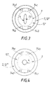
- Figure 3 shows a schematic top view from the downstream end 4 of the nozzle 3 shown in the Figure 2. More specifically, we see the sleeve 5 surrounding the nozzle 3 whose downstream end 4 is shaped flattened.
- the plate 12 ' is fixed by the means of holding 12 "at the sleeve 5 and / or at the end 4 of the nozzle 3 and has a perforation 13, in which is inserted said end 4 of the nozzle 3.
- the gas dry protection contained inside the sleeve 5 is evacuated through the orifices 14a, 14b, 14c and 14d while preventing thus the atmospheric air to penetrate inside said sleeve 5.
- the arrangement, in particular the part 12, shown in Figure 1 is not limited to substantially circular section nozzles and that it can also be suitable for nozzles with a flat section, such as that shown in Figure 2.
- the arrangement constituted by the plate 12 'of Figure 2 is not limited to flat section nozzles, but can be adapted to circular section nozzles, such as that shown in FIG. 1, with an adaptation to the range of one skilled in the art.
- FIG. 4 which is in all respects analogous to the Figure 3, except that the nozzle shown this time, not a flat section, but a substantially circular section 4, such as that of the nozzle 3 shown in FIG. 1.
- nozzles having one end of circular shape and those at the end flattened, make it possible to obtain liquid jets refrigerant of different shapes and are therefore used for different applications.
- a heat treatment device provided with a round jet cooling nozzle (circular end) and delivering a CO 2 type coolant was used.
- the nozzle is equipped at its downstream end with a protective sleeve into which gas is introduced protection, so to create a sweep on the part downstream of the carbon dioxide spray nozzle.
- the shielding gas used is industrial compressed air, which is previously filtered mainly to remove moisture, but also the fat from compression.
- a sweep of said nozzle is carried out by means of compressed dry air and filtered.
- This device gives complete satisfaction at the start, that is, for the first 5-10 minutes no icing of the downstream end of the nozzle is observed. However, after this time, a slight condensation on the downstream end of the nozzle appears from by saturation in humidity of the filter used for purify the compressed air serving as a protective gas.
- This example 2 is completely analogous to the example 1, except that in this case the gas protection used is not dry compressed air, but nitrogen gas, which is, on the one hand, easier to handle and, on the other hand, does not require filtering.
- N45 nitrogen has maximum water and oxygen of the order of 5 ppm (part per million in volume) while standard N25 nitrogen has a content maximum water of the order of 40 ppm and its content oxygen is variable.
- standard nitrogen N25 or nitrogen N45 can be used effectively to form a gas protection against icing of the nozzles distributing a refrigerant, such as CO2, used in processes heat treatment.
- this example 2 confirms that the slight condensation appeared on the nozzle in example 1 is good the result of saturation of the filter with humidity.
- the shielding gas is delivered at a flow rate of the order of 15 l / min and at a pressure of approximately 1.2 ⁇ 10 5 Pa.
Landscapes
- Chemical & Material Sciences (AREA)
- Engineering & Computer Science (AREA)
- Mechanical Engineering (AREA)
- Physics & Mathematics (AREA)
- Materials Engineering (AREA)
- Thermal Sciences (AREA)
- Metallurgy (AREA)
- Organic Chemistry (AREA)
- Crystallography & Structural Chemistry (AREA)
- Plasma & Fusion (AREA)
- Chemical Kinetics & Catalysis (AREA)
- Combustion & Propulsion (AREA)
- General Engineering & Computer Science (AREA)
- Nozzles (AREA)
- Furnace Details (AREA)
Abstract
Description
- le jet réfrigérant sortant des buses entre en contact intime avec le matériau-substrat;
- le débit et la forme du jet réfrigérant soient stables et réguliers dans le temps afin d'éviter les pulsations, c'est-à-dire une distribution par à-coups, dont l'une des causes est la condensation de la vapeur d'eau atmosphérique sur les buses;
- la perturbation occasionnée par le jet de fluide réfrigérant sur le jet constitué essentiellement de gaz chaud et, selon le cas, de particules en fusion soit minimale;
- les différents débits soient adaptés en fonction de la position des buses délivrant le fluide réfrigérant par rapport à celle des buses ou torches de projection thermique;
- la forme plutôt aplatie ou plutôt cylindrique de la buse délivrant le fluide réfrigérant soit adaptée au cas d'espèce.
caractérisé en ce qu'il comprend, en outre, des moyens de protection agencés de manière à assurer le maintien d'une atmosphère gazeuse de protection sur au moins une partie desdits moyens de distribution.
- des moyens de projection délivrant au moins un jet contenant au moins un gaz vecteur chaud, et
- des moyens de refroidissement comprenant des moyens de distribution délivrant au moins un fluide de refroidissement,
- les moyens de distribution sont une ou plusieurs buses de distribution,
- lesdits moyens de protection comportent un manchon entourant, au moins partiellement, la ou les buses de distribution,
- ledit manchon est fixé par une extrémité proximale auxdits moyens de distribution et, de préférence, en amont de la buse,
- ledit manchon comporte une extrémité distale libre et, de préférence, présentant un rétrécissement,
- ledit manchon comporte une extrémité distale obturée partiellement par un moyen d'obturation,
- ledit manchon comporte au moins un orifice par lequel est introduit le flux gazeux de protection acheminé par les moyens d'alimentation,
- la buse de distribution comporte une extrémité de section circulaire ou ovale, ou de section aplatie.
- on effectue une projection, sur au moins une partie de la surface dudit matériau, d'au moins un jet contenant au moins un gaz vecteur chaud,
- on refroidit au moins une partie dudit matériau au moyen d'au moins une buse de distribution délivrant un fluide réfrigérant,
- on maintient au moins une partie de la buse de distribution sous une atmosphère gazeuse de protection au moyen d'au moins un gaz de protection.
- on maintient la buse de distribution sous une atmosphère gazeuse de protection en soumettant ladite buse à un balayage par ledit flux gazeux de protection.
- le jet chaud de projection comporte, en outre, des particules d'un matériau en fusion au moins partielle ou ramollies, c'est-à-dire sous une forme "pâteuse", et, de préférence, d'un matériau choisi dans le groupe formé par les métaux, les alliages de métaux, les céramiques, les plastiques ou polymères, la silice et les oxydes métalliques,
- le fluide réfrigérant est choisi parmi l'azote, le dioxyde de carbone, l'argon et les mélanges les comprenant,
- le balayage est effectué au moyen d'au moins un gaz sec et, de préférence, un gaz choisi dans le groupe formé par l'air sec, l'azote, l'hélium, l'argon et les mélanges les contenant. De manière générale, conviennent également les gaz ou mélanges gazeux permettant de modifier la mouillabilité des particules en fusion ou du refroidissement vis-à-vis du matériau-substrat,
- l'atmosphère gazeuse de protection est, dans le manchon, à une pression supérieure, à 0,9.105 Pa, de préférence, supérieure ou égale à 105 Pa, avantageusement comprise dans la gamme 1,1.105 Pa à 3.105 Pa, avantageusement encore dans la gamme 1,1.105 Pa à 2.105 Pa,
- le débit du flux gazeux de protection est fonction de la géométrie, en particulier du diamètre, de la buse. Ainsi, pour une buse de 0,5 mm à 30 mm de diamètre, le débit du flux de protection est compris, de préférence, dans la gamme 5 l/min à 30 l/min et pour une buse de 1 mm à 10 mm de diamètre, dans la gamme 8 l/min à 25 l/min.
- la figure 1 représente, de façon schématique, une vue en coupe longitudinale d'un premier mode de réalisation d'un dispositif selon l'invention;
- la figure 2 représente, de façon schématique, une vue en coupe longitudinale d'un deuxième mode de réalisation d'un dispositif selon l'invention;
- la figure 3 représente une vue de dessus du dispositif représenté sur la figure 2;
- et la figure 4 est analogue à la figure 3 à l'exception du fait que le dispositif représenté est cette fois muni d'une buse à section sensiblement circulaire.
Claims (17)
- Dispositif de traitement thermique comportant des moyens de refroidissement (1, 2, 3, 4, 4') comprenant des moyens de distribution (3, 4, 4') délivrant au moins un fluide de refroidissement, caractérisé en ce qu'il comprend, en outre, des moyens de protection (5, 5a, 5b, 12, 12') agencés de manière à assurer le maintien d'une atmosphère gazeuse de protection sur au moins une partie desdits moyens de distribution (3, 4, 4').
- Dispositif selon la revendication 1, caractérisé en ce que les moyens de protection (5, 5a, 5b, 12, 12') sont reliés à des moyens d'alimentation (6, 16, 17) en au moins un flux gazeux de protection.
- Dispositif comportant :caractérisé en ce qu'il comprend, en outre, des moyens de protection (5, 5a, 5b, 12, 12') reliés à des moyens d'alimentation (6, 16, 17) en au moins un flux gazeux de protection, lesdits moyens de protection (5, 5a, 5b, 12, 12') étant agencés de manière à assurer le maintien d'une atmosphère gazeuse de protection sur au moins une partie desdits moyens de distribution (3, 4, 4').des moyens de projection délivrant au moins un jet contenant au moins un gaz vecteur chaud, etdes moyens de refroidissement (1, 2, 3, 4, 4') comprenant des moyens de distribution (3, 4, 4') délivrant au moins un fluide de refroidissement,
- Dispositif selon l'une des revendications 1 à 3, caractérisé en ce que les moyens de distribution (3, 4, 4') sont une ou plusieurs buses (3) de distribution.
- Dispositif selon l'une des revendications 1 à 4, caractérisé en ce que lesdits moyens de protection (5, 5a, 5b, 12, 12') comportent un manchon (5) entourant, au moins partiellement, la ou les buses (3) de distribution.
- Dispositif selon l'une des revendications 1 à 5, caractérisé en ce que ledit manchon (5) est fixé par une extrémité proximale (5a) auxdits moyens de distribution (3, 4, 4') et, de préférence, en amont de la buse (3).
- Dispositif selon l'une des revendications 1 à 6, caractérisé en ce que ledit manchon (5) comporte une extrémité distale (5b) libre et, de préférence, présentant un rétrécissement (12).
- Dispositif selon l'une des revendications 1 à 7, caractérisé en ce que ledit manchon (5) comporte une extrémité distale (5b) obturée partiellement par un moyen d'obturation (12, 12').
- Dispositif selon l'une des revendications 1 à 6, caractérisé en ce que ledit manchon (5) comporte au moins un orifice (3) par lequel est introduit le flux gazeux de protection acheminé par les moyens d'alimentation (6, 16, 17).
- Procédé de traitement thermique d'un matériau, dans lequel :on effectue une projection, sur au moins une partie de la surface dudit matériau, d'au moins un jet contenant au moins un gaz vecteur chaud,on refroidit au moins une partie dudit matériau au moyen d'au moins une buse de distribution délivrant un fluide réfrigérant,on maintient au moins une partie de la buse de distribution sous une atmosphère gazeuse de protection au moyen d'au moins un gaz de protection.
- Procédé selon la revendication 10, caractérisé en ce qu'on maintient la buse de distribution sous une atmosphère gazeuse de protection en soumettant ladite buse à un balayage par ledit flux gazeux de protection.
- Procédé selon l'une des revendications 10 ou 11, caractérisé en ce que le jet de projection comporte, en outre, des particules d'un matériau en fusion au moins partielle ou ramollies et, de préférence, d'un matériau choisi dans le groupe formé par les métaux, les alliages de métaux, les céramiques, les plastiques, la silice et les oxydes métalliques.
- Procédé selon l'une des revendications 10 à 13, caractérisé en ce que le balayage est effectué au moyen d'au moins un gaz sec et, de préférence, un gaz choisi dans le groupe formé par l'air sec, l'azote, l'hélium, l'argon et des mélanges les contenant.
- Procédé de revêtement de surface mettant en oeuvre un dispositif selon l'une des revendications 1 à 9 ou un procédé selon l'une des revendications 1 à 13.
- Manchon de protection susceptible d'équiper un dispositif selon l'une des revendications 1 à 9 ou d'être utilisé pour mettre en oeuvre un procédé selon l'une des revendications 10 à 14.
- Utilisation du dispositif selon l'une des revendications 1 à 9 dans un procédé de traitement thermique d'une pièce en un matériau choisi parmi les métaux, les alliages de métaux, les polymères, les matériaux organiques et minéraux.
- Pièce susceptible d'être fabriquée par un procédé mettant en oeuvre un dispositif selon l'une des revendications 1 à 9.
Applications Claiming Priority (2)
| Application Number | Priority Date | Filing Date | Title |
|---|---|---|---|
| FR9705230 | 1997-04-28 | ||
| FR9705230A FR2762667B1 (fr) | 1997-04-28 | 1997-04-28 | Dispositif et procede de traitement thermique |
Publications (2)
| Publication Number | Publication Date |
|---|---|
| EP0872563A1 true EP0872563A1 (fr) | 1998-10-21 |
| EP0872563B1 EP0872563B1 (fr) | 2000-05-24 |
Family
ID=9506378
Family Applications (1)
| Application Number | Title | Priority Date | Filing Date |
|---|---|---|---|
| EP98400761A Revoked EP0872563B1 (fr) | 1997-04-28 | 1998-03-31 | Dispositif et procédé de traitement thermique |
Country Status (8)
| Country | Link |
|---|---|
| US (1) | US5989647A (fr) |
| EP (1) | EP0872563B1 (fr) |
| JP (1) | JPH1144489A (fr) |
| CA (1) | CA2235423A1 (fr) |
| DE (1) | DE69800158T2 (fr) |
| ES (1) | ES2147039T3 (fr) |
| FR (1) | FR2762667B1 (fr) |
| GR (1) | GR3033691T3 (fr) |
Cited By (6)
| Publication number | Priority date | Publication date | Assignee | Title |
|---|---|---|---|---|
| WO2000007790A1 (fr) * | 1998-08-06 | 2000-02-17 | Aga Aktiebolag | Refroidissement ponctuel |
| EP1091181A1 (fr) * | 1999-10-05 | 2001-04-11 | Linde Gas Aktiengesellschaft | Buse d'expansion |
| EP1152198A1 (fr) * | 2000-05-03 | 2001-11-07 | Carboxyque Française | Dispositif de refroidissement en ligne |
| WO2002087803A1 (fr) * | 2001-05-01 | 2002-11-07 | Air Products And Chemicals, Inc. | Procede et cage de laminage pour laminage a froid d'une bande metallique |
| WO2008074301A2 (fr) | 2006-12-21 | 2008-06-26 | Forschungszentrum Jülich GmbH | Procédé et dispositif pour un procédé de projection thermique |
| WO2022042330A1 (fr) * | 2020-08-27 | 2022-03-03 | 四川航天川南火工技术有限公司 | Appareil de refroidissement de gaz de poudre |
Families Citing this family (25)
| Publication number | Priority date | Publication date | Assignee | Title |
|---|---|---|---|---|
| US6495966B2 (en) * | 1999-09-08 | 2002-12-17 | Matsushita Electric Industrial Co., Ltd. | Field emission display including a resistor |
| US20020018851A1 (en) * | 2000-06-21 | 2002-02-14 | Edward Chang | Manufacturing method for surgical implants having a layer of bioactive ceramic coating |
| KR20040101948A (ko) * | 2004-05-31 | 2004-12-03 | (주)케이.씨.텍 | 표면세정용 승화성 고체입자 분사용 노즐 및 이를 이용한 세정방법 |
| US20090246398A1 (en) * | 2006-08-14 | 2009-10-01 | Nakayama Steel Works ,Ltd. | Method and apparatus for forming amorphous coating film |
| BRPI0715966A2 (pt) * | 2006-08-28 | 2013-08-06 | Air Prod & Chem | aparelho, e mÉtodo |
| US20080196416A1 (en) * | 2007-02-16 | 2008-08-21 | John Martin Girard | Method and system for liquid cryogen injection in mixing or blending devices |
| US20090000710A1 (en) * | 2007-06-28 | 2009-01-01 | Caterpillar Inc. | Quenching process utilizing compressed air |
| WO2010019144A1 (fr) * | 2008-08-14 | 2010-02-18 | Praxair Technology, Inc. | Système et procédé pour l'injection de cryogène liquide dans des dispositifs manquants ou de mélange |
| DE102008064083A1 (de) | 2008-12-19 | 2010-06-24 | Messer Group Gmbh | Vorrichtung und Verfahren zum Kühlen von Oberflächen |
| KR100994483B1 (ko) * | 2010-07-21 | 2010-11-16 | 이돈구 | 수류안마장치 |
| US8978396B2 (en) * | 2012-06-22 | 2015-03-17 | L'air Liquide Societe, Anonyme Pour L'etude Et L'exploitation Des Procedes Georges Claude | Vent ice prevention method |
| US8997504B2 (en) * | 2012-12-12 | 2015-04-07 | L'air Liquide, Societe Anonyme Pour L'etude Et L'exploitation Des Procedes Georges Claude | Vent ice prevention method |
| MX2014012688A (es) * | 2013-11-29 | 2015-05-28 | Müller Martini Holding AG | Un metodo para aplicar una sustancia fluida. |
| DE102014114394B3 (de) * | 2014-10-02 | 2015-11-05 | Voestalpine Stahl Gmbh | Verfahren zum Erzeugen eines gehärteten Stahlblechs |
| US10619223B2 (en) | 2016-04-28 | 2020-04-14 | GM Global Technology Operations LLC | Zinc-coated hot formed steel component with tailored property |
| US10385415B2 (en) | 2016-04-28 | 2019-08-20 | GM Global Technology Operations LLC | Zinc-coated hot formed high strength steel part with through-thickness gradient microstructure |
| CN106399892A (zh) * | 2016-11-30 | 2017-02-15 | 国家电网公司 | 一种热喷涂方法及其设备 |
| US11613789B2 (en) | 2018-05-24 | 2023-03-28 | GM Global Technology Operations LLC | Method for improving both strength and ductility of a press-hardening steel |
| CN112534078A (zh) | 2018-06-19 | 2021-03-19 | 通用汽车环球科技运作有限责任公司 | 具有增强的机械性质的低密度压制硬化钢 |
| US11530469B2 (en) | 2019-07-02 | 2022-12-20 | GM Global Technology Operations LLC | Press hardened steel with surface layered homogenous oxide after hot forming |
| WO2021138545A1 (fr) | 2019-12-31 | 2021-07-08 | Cold Jet, Llc | Procédé et appareil pour un flux de soufflage amélioré |
| CN111471841B (zh) * | 2020-04-17 | 2021-12-03 | 广东万润利模具技术有限公司 | 一种高精度热风式表面热处理控制系统 |
| CN111649950A (zh) * | 2020-06-24 | 2020-09-11 | 湖南汉能科技有限公司 | 一种喷嘴性能试验平台 |
| JP7680835B2 (ja) * | 2020-12-28 | 2025-05-21 | 三菱重工航空エンジン株式会社 | 遮熱コーティングの施工方法及び耐熱部材 |
| CN116212609B (zh) * | 2023-04-18 | 2023-09-22 | 江苏顺仕净化设备有限公司 | 一种机械加工车间用空气净化装置 |
Citations (4)
| Publication number | Priority date | Publication date | Assignee | Title |
|---|---|---|---|---|
| GB1452062A (en) * | 1972-10-10 | 1976-10-06 | Boc International Ltd | Metal treatment |
| FR2347111A1 (fr) * | 1976-04-07 | 1977-11-04 | Agefko Kohlensaeure Ind | Procede de revetement superficiel a l'aide d'un jet de gaz chaud et de materiau fondu |
| EP0124432A1 (fr) * | 1983-04-29 | 1984-11-07 | Commissariat A L'energie Atomique | Procédé et dispositif pour le revêtement d'une pièce par projection de plasma |
| EP0546359A1 (fr) * | 1991-12-12 | 1993-06-16 | Linde Aktiengesellschaft | Procédé de dépôt par pulvérisation thermique avec refroidissement |
Family Cites Families (3)
| Publication number | Priority date | Publication date | Assignee | Title |
|---|---|---|---|---|
| US4068495A (en) * | 1976-03-31 | 1978-01-17 | The United States Of America As Represented By The United States National Aeronautics And Space Administration | Closed loop spray cooling apparatus |
| EP0183707B1 (fr) * | 1984-03-12 | 1988-11-09 | Commissariat A L'energie Atomique | Traitement de surface d'une piece pour ameliorer l'adherence d'un revetement depose ensuite sur la piece, par projection a chaud |
| ATE160055T1 (de) * | 1990-09-07 | 1997-11-15 | Sulzer Metco Ag | Apparatur zur plasmathermischen bearbeitung von werkstückoberflächen |
-
1997
- 1997-04-28 FR FR9705230A patent/FR2762667B1/fr not_active Expired - Fee Related
-
1998
- 1998-03-31 ES ES98400761T patent/ES2147039T3/es not_active Expired - Lifetime
- 1998-03-31 DE DE69800158T patent/DE69800158T2/de not_active Revoked
- 1998-03-31 EP EP98400761A patent/EP0872563B1/fr not_active Revoked
- 1998-04-15 US US09/060,463 patent/US5989647A/en not_active Expired - Fee Related
- 1998-04-20 CA CA002235423A patent/CA2235423A1/fr not_active Abandoned
- 1998-04-27 JP JP10117399A patent/JPH1144489A/ja active Pending
-
2000
- 2000-06-15 GR GR20000401378T patent/GR3033691T3/el not_active IP Right Cessation
Patent Citations (4)
| Publication number | Priority date | Publication date | Assignee | Title |
|---|---|---|---|---|
| GB1452062A (en) * | 1972-10-10 | 1976-10-06 | Boc International Ltd | Metal treatment |
| FR2347111A1 (fr) * | 1976-04-07 | 1977-11-04 | Agefko Kohlensaeure Ind | Procede de revetement superficiel a l'aide d'un jet de gaz chaud et de materiau fondu |
| EP0124432A1 (fr) * | 1983-04-29 | 1984-11-07 | Commissariat A L'energie Atomique | Procédé et dispositif pour le revêtement d'une pièce par projection de plasma |
| EP0546359A1 (fr) * | 1991-12-12 | 1993-06-16 | Linde Aktiengesellschaft | Procédé de dépôt par pulvérisation thermique avec refroidissement |
Cited By (9)
| Publication number | Priority date | Publication date | Assignee | Title |
|---|---|---|---|---|
| WO2000007790A1 (fr) * | 1998-08-06 | 2000-02-17 | Aga Aktiebolag | Refroidissement ponctuel |
| US6412288B1 (en) | 1998-08-06 | 2002-07-02 | Aga Aktiebolag | Point cooling |
| EP1091181A1 (fr) * | 1999-10-05 | 2001-04-11 | Linde Gas Aktiengesellschaft | Buse d'expansion |
| EP1152198A1 (fr) * | 2000-05-03 | 2001-11-07 | Carboxyque Française | Dispositif de refroidissement en ligne |
| FR2808585A1 (fr) * | 2000-05-03 | 2001-11-09 | Carboxyque Francaise | Dispositif de refroidissement en ligne |
| WO2002087803A1 (fr) * | 2001-05-01 | 2002-11-07 | Air Products And Chemicals, Inc. | Procede et cage de laminage pour laminage a froid d'une bande metallique |
| WO2008074301A2 (fr) | 2006-12-21 | 2008-06-26 | Forschungszentrum Jülich GmbH | Procédé et dispositif pour un procédé de projection thermique |
| WO2008074301A3 (fr) * | 2006-12-21 | 2009-06-04 | Forschungszentrum Juelich Gmbh | Procédé et dispositif pour un procédé de projection thermique |
| WO2022042330A1 (fr) * | 2020-08-27 | 2022-03-03 | 四川航天川南火工技术有限公司 | Appareil de refroidissement de gaz de poudre |
Also Published As
| Publication number | Publication date |
|---|---|
| GR3033691T3 (en) | 2000-10-31 |
| FR2762667A1 (fr) | 1998-10-30 |
| CA2235423A1 (fr) | 1998-10-28 |
| EP0872563B1 (fr) | 2000-05-24 |
| DE69800158D1 (de) | 2000-06-29 |
| FR2762667B1 (fr) | 1999-05-28 |
| ES2147039T3 (es) | 2000-08-16 |
| DE69800158T2 (de) | 2000-11-23 |
| JPH1144489A (ja) | 1999-02-16 |
| US5989647A (en) | 1999-11-23 |
Similar Documents
| Publication | Publication Date | Title |
|---|---|---|
| EP0872563B1 (fr) | Dispositif et procédé de traitement thermique | |
| EP2501888B1 (fr) | Procédé de fabrication d'un vitrage isolant | |
| EP0755720B1 (fr) | Dispositif de pulvérisation d'un produit liquide | |
| EP2401245B1 (fr) | Dispositif comportant un tube céramique revetu et une frette | |
| EP0506552B1 (fr) | Procédé pour traiter par exemple la surface d'un substrat par projection d'un flux de plasma, et dispositif pour la mise en oeuvre du procédé | |
| FR2772118A1 (fr) | Procede de combustion et bruleur a pulverisation de combustible mettant en oeuvre un tel procede | |
| WO2008142222A1 (fr) | Procédé de revêtement d'un substrat et installation de dépôt sous vide d'alliage métallique | |
| FR2642673A1 (fr) | Tuyere de pulverisation a laser a ecoulement transversal et procede correspondant | |
| FR2595684A1 (fr) | Procede de lubrification d'un moule pour la fabrication d'un recipient en verre | |
| FR2463752A1 (fr) | Poudre pour la formation d'un enduit a proprietes thermiques | |
| EP0479678B1 (fr) | Procédé de revêtement de vitrages par un procédé de projection thermique | |
| EP0965792B1 (fr) | Brûleur à injecteur perfectionné et procédé de fabrication de cet injecteur | |
| EP3320129B1 (fr) | Machine de fabrication additive contenant un dispositif mettant en oeuvre in-situ un procédé permettant de retirer les oxydes présents à la surface des nodules d'une poudre métallique avant l'utilisation de celle-ci dans la fabrication additive par fusion | |
| CA1200689A (fr) | Embout de lance de gunitage a chaud | |
| FR2511698A1 (fr) | Tube pour le craquage ou reformage thermique des hydrocarbures et son procede de fabrication | |
| FR2633944A1 (fr) | Procede pour le revetement de surfaces par du noir de carbone | |
| EP0954619B1 (fr) | Procede et dispositif pour la realisation d'un revetement sur un substrat | |
| CH617499A5 (en) | Support for electromagnetic brake or clutch | |
| FR2663342A1 (fr) | Revetement de protection d'une piece metallique en alliage de titane et procede de depot. | |
| EP0077857A1 (fr) | Emaillage d'un substrat avec un verre fluoré | |
| EP0495764B1 (fr) | Dispositif de préchauffage d'une busette de coulée d'un métal en fusion | |
| EP0406208B1 (fr) | Dispositif de préchauffage d'une busette de coulée d'un métal en fusion et installation de coulée d'un métal équipée de ce dispositif | |
| FR2715168A1 (fr) | Procédé pour déposer, à la température ambiante, une couche de métal ou de semi-métal et leur oxyde sur un substrat. | |
| EP2371994B1 (fr) | Procédé pour réaliser un revêtement d'acier inoxydable sur une matrice en cuivre | |
| FR2808461A1 (fr) | Procede de reduction des frottements entre au moins deux pieces metalliques et piston obtenu par le procede |
Legal Events
| Date | Code | Title | Description |
|---|---|---|---|
| PUAI | Public reference made under article 153(3) epc to a published international application that has entered the european phase |
Free format text: ORIGINAL CODE: 0009012 |
|
| AK | Designated contracting states |
Kind code of ref document: A1 Designated state(s): BE CH DE DK ES FR GR IT LI NL SE |
|
| AX | Request for extension of the european patent |
Free format text: AL;LT;LV;MK;RO;SI |
|
| RIN1 | Information on inventor provided before grant (corrected) |
Inventor name: LIAO, HAN LIN Inventor name: PESME, FRANCOIS Inventor name: CODDET, CHRISTIAN Inventor name: GOURLAOUEN, VINCENT Inventor name: HANSZ, BERNARD Inventor name: REMY, FRANCIS |
|
| 17P | Request for examination filed |
Effective date: 19990421 |
|
| AKX | Designation fees paid |
Free format text: BE CH DE DK ES FR GR IT LI NL SE |
|
| 17Q | First examination report despatched |
Effective date: 19990614 |
|
| GRAG | Despatch of communication of intention to grant |
Free format text: ORIGINAL CODE: EPIDOS AGRA |
|
| GRAG | Despatch of communication of intention to grant |
Free format text: ORIGINAL CODE: EPIDOS AGRA |
|
| GRAH | Despatch of communication of intention to grant a patent |
Free format text: ORIGINAL CODE: EPIDOS IGRA |
|
| GRAH | Despatch of communication of intention to grant a patent |
Free format text: ORIGINAL CODE: EPIDOS IGRA |
|
| GRAA | (expected) grant |
Free format text: ORIGINAL CODE: 0009210 |
|
| AK | Designated contracting states |
Kind code of ref document: B1 Designated state(s): BE CH DE DK ES FR GR IT LI NL SE |
|
| REG | Reference to a national code |
Ref country code: CH Ref legal event code: EP |
|
| ITF | It: translation for a ep patent filed | ||
| REF | Corresponds to: |
Ref document number: 69800158 Country of ref document: DE Date of ref document: 20000629 |
|
| REG | Reference to a national code |
Ref country code: ES Ref legal event code: FG2A Ref document number: 2147039 Country of ref document: ES Kind code of ref document: T3 |
|
| PG25 | Lapsed in a contracting state [announced via postgrant information from national office to epo] |
Ref country code: DK Free format text: LAPSE BECAUSE OF FAILURE TO SUBMIT A TRANSLATION OF THE DESCRIPTION OR TO PAY THE FEE WITHIN THE PRESCRIBED TIME-LIMIT Effective date: 20000824 |
|
| PGFP | Annual fee paid to national office [announced via postgrant information from national office to epo] |
Ref country code: GR Payment date: 20010228 Year of fee payment: 4 |
|
| PLBQ | Unpublished change to opponent data |
Free format text: ORIGINAL CODE: EPIDOS OPPO |
|
| PGFP | Annual fee paid to national office [announced via postgrant information from national office to epo] |
Ref country code: BE Payment date: 20010309 Year of fee payment: 4 |
|
| PLBI | Opposition filed |
Free format text: ORIGINAL CODE: 0009260 |
|
| PLBF | Reply of patent proprietor to notice(s) of opposition |
Free format text: ORIGINAL CODE: EPIDOS OBSO |
|
| 26 | Opposition filed |
Opponent name: LINDE AKTIENGESELLSCHAFT Effective date: 20010226 |
|
| PLBF | Reply of patent proprietor to notice(s) of opposition |
Free format text: ORIGINAL CODE: EPIDOS OBSO |
|
| NLR1 | Nl: opposition has been filed with the epo |
Opponent name: LINDE AKTIENGESELLSCHAFT |
|
| PGFP | Annual fee paid to national office [announced via postgrant information from national office to epo] |
Ref country code: FR Payment date: 20020211 Year of fee payment: 5 |
|
| PGFP | Annual fee paid to national office [announced via postgrant information from national office to epo] |
Ref country code: CH Payment date: 20020214 Year of fee payment: 5 |
|
| PGFP | Annual fee paid to national office [announced via postgrant information from national office to epo] |
Ref country code: SE Payment date: 20020218 Year of fee payment: 5 |
|
| PGFP | Annual fee paid to national office [announced via postgrant information from national office to epo] |
Ref country code: DE Payment date: 20020221 Year of fee payment: 5 |
|
| PGFP | Annual fee paid to national office [announced via postgrant information from national office to epo] |
Ref country code: NL Payment date: 20020225 Year of fee payment: 5 |
|
| PGFP | Annual fee paid to national office [announced via postgrant information from national office to epo] |
Ref country code: ES Payment date: 20020308 Year of fee payment: 5 |
|
| PG25 | Lapsed in a contracting state [announced via postgrant information from national office to epo] |
Ref country code: BE Free format text: LAPSE BECAUSE OF NON-PAYMENT OF DUE FEES Effective date: 20020331 |
|
| RAP2 | Party data changed (patent owner data changed or rights of a patent transferred) |
Owner name: L'AIR LIQUIDE, S.A. A DIRECTOIRE ET CONSEIL DE SUR |
|
| NLT2 | Nl: modifications (of names), taken from the european patent patent bulletin |
Owner name: L'AIR LIQUIDE, S.A. A DIRECTOIRE ET CONSEIL DE SUR |
|
| BERE | Be: lapsed |
Owner name: S.A. L'*AIR LIQUIDE POUR L'ETUDE ET L'EXPLOITATION Effective date: 20020331 |
|
| RDAH | Patent revoked |
Free format text: ORIGINAL CODE: EPIDOS REVO |
|
| RDAG | Patent revoked |
Free format text: ORIGINAL CODE: 0009271 |
|
| STAA | Information on the status of an ep patent application or granted ep patent |
Free format text: STATUS: PATENT REVOKED |
|
| REG | Reference to a national code |
Ref country code: CH Ref legal event code: PL |
|
| 27W | Patent revoked |
Effective date: 20020927 |
|
| REG | Reference to a national code |
Ref country code: SE Ref legal event code: ECNC |