EP0871270B1 - Handwerkzeug - Google Patents
Handwerkzeug Download PDFInfo
- Publication number
- EP0871270B1 EP0871270B1 EP98301893A EP98301893A EP0871270B1 EP 0871270 B1 EP0871270 B1 EP 0871270B1 EP 98301893 A EP98301893 A EP 98301893A EP 98301893 A EP98301893 A EP 98301893A EP 0871270 B1 EP0871270 B1 EP 0871270B1
- Authority
- EP
- European Patent Office
- Prior art keywords
- cable
- hand tool
- holder
- opening
- received
- Prior art date
- Legal status (The legal status is an assumption and is not a legal conclusion. Google has not performed a legal analysis and makes no representation as to the accuracy of the status listed.)
- Expired - Lifetime
Links
- 238000005520 cutting process Methods 0.000 claims description 62
- 238000003780 insertion Methods 0.000 claims description 10
- 230000037431 insertion Effects 0.000 claims description 10
- 230000000295 complement effect Effects 0.000 claims 1
- 239000004020 conductor Substances 0.000 description 11
- 230000000694 effects Effects 0.000 description 10
- 239000004033 plastic Substances 0.000 description 4
- 229920003023 plastic Polymers 0.000 description 4
- 235000013290 Sagittaria latifolia Nutrition 0.000 description 3
- 235000015246 common arrowhead Nutrition 0.000 description 3
- 238000002347 injection Methods 0.000 description 3
- 239000007924 injection Substances 0.000 description 3
- 238000009413 insulation Methods 0.000 description 2
- 239000000463 material Substances 0.000 description 2
- 241000590913 Euploea core Species 0.000 description 1
- 239000004952 Polyamide Substances 0.000 description 1
- 230000006835 compression Effects 0.000 description 1
- 238000007906 compression Methods 0.000 description 1
- 238000010276 construction Methods 0.000 description 1
- 238000000034 method Methods 0.000 description 1
- 230000003287 optical effect Effects 0.000 description 1
- 230000002093 peripheral effect Effects 0.000 description 1
- 229920002647 polyamide Polymers 0.000 description 1
- 210000003813 thumb Anatomy 0.000 description 1
- 238000009966 trimming Methods 0.000 description 1
Images


Classifications
-
- H—ELECTRICITY
- H02—GENERATION; CONVERSION OR DISTRIBUTION OF ELECTRIC POWER
- H02G—INSTALLATION OF ELECTRIC CABLES OR LINES, OR OF COMBINED OPTICAL AND ELECTRIC CABLES OR LINES
- H02G1/00—Methods or apparatus specially adapted for installing, maintaining, repairing or dismantling electric cables or lines
- H02G1/12—Methods or apparatus specially adapted for installing, maintaining, repairing or dismantling electric cables or lines for removing insulation or armouring from cables, e.g. from the end thereof
- H02G1/1202—Methods or apparatus specially adapted for installing, maintaining, repairing or dismantling electric cables or lines for removing insulation or armouring from cables, e.g. from the end thereof by cutting and withdrawing insulation
- H02G1/1204—Hand-held tools
- H02G1/1221—Hand-held tools the cutting element rotating about the wire or cable
- H02G1/1224—Hand-held tools the cutting element rotating about the wire or cable making a transverse cut
Definitions
- This invention relates to a hand tool for use with cable, principally electrical/electronic/optical cable, and particularly provides means for cutting such cable and/or for stripping off sleeving from conductors thereof.
- the cable may, for example, be that conventionally used with domestic appliances, having a relatively thick outer sleeve enclosing two of three inner conductors with thinner sleeves respectively, or it may be in the form of co-axial computer cable with a relatively thin outer sleeve.
- the tool can also be used to strip single wires, and to twist multi-strand wires for insertion into plug terminals.
- Hand tools for cutting cables are known, for example, from DE 19543390 and GB 2173958.
- a blade holder is provided which is movably mounted in a body for movement to a position whereat a knife blade extends across an opening for cutting a cable received in the opening.
- biasing means are provided for biasing the blade holder inwardly of the body so as to urge the blade into contact with a cable received in the opening.
- the blade holder is movable in an outwards direction from the body in order to move the blade to a position to clear the opening to allow insertion of a cable therethrough.
- An object of the invention is to provide such a hand tool in a convenient and effective form.
- the term 'cable' includes an individual core in a multi-core cable, as well as the complete cable made up of one or more of such cores each within an outer sleeve.
- Each core may be formed with an individual sleeve around a conductor or may be merely a conductor, projecting from an enveloping outer sleeve.
- the term 'cable' as used herein, also includes wires, cords and flexes, as well as cable itself.
- the hand tool includes means for adjusting the maximum depth of cut possible, i.e. cutting depth, between the cable and said cutting element. This allows said maximum depth of cut into the cable to be adapted as required for different thicknesses of cable sleeves, and also thus allows the cable to be stripped rather than complete severed.
- the cutting element is pivotally movable within the body.
- the depth of cut in the cable is adjustable by operation of a manually slidable member which controls adjustment movement of an anvil member so as to uncover a greater or lesser amount of the cutting element.
- pressure relief means for relieving biasing/cutting force on an inserted cable/core.
- the hand tool of the present invention is for use with electrical flex or cable, both for cutting such cable and also for stripping insulating/shielding sleeving from the cable or from electrical conductors or cores forming the interior of the cable. It can also be used to twist multi-strand wires for insertion into plug terminals.
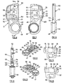
- the hand tool as shown assembled in Figure 33, has a body made up of a first body part 10 and a second body part 11 which are generally similarly peripherally shaped and which are arranged to interfit together so that the first body part 10 forms the front and sides of the hand tool, whilst the second body part 11 forms the rear of the tool.
- a cutting blade holder 12 Pivotally mounted at the body is a cutting blade holder 12 which normally lies partly within the body and is movable further into the body when cable is to be inserted through it for being operated on by the cutting blade 13 of the cutting blade holder 12.
- the cutting blade holder is biased to its outer position relative to the body by means of a blade spring 14 which has one end anchored in the body and the other end bearing on the holder 12.
- the embodiments of the hand tool of the invention described herein also incorporate a preferable feature, namely that the depth of cut is adjustable for different types of cable, and to this end the cutting blade holder 12 carries a movable anvil member 15, the movement of which is controlled by a slidable operating button 16 which, in the normal outwardly biased position of the cutting blade holder 12, is capable of manual sliding movement so as to adjust the position of the anvil relative to the cutting blade 13 and thus alter the depth of cut.
- Both of the first and second body parts and also the cutting blade holder would normally be injection moulded in plastics material, such as ABS or polyamide.
- the anvil member and the operating button would also normally be injection moulded.
- the first body part 10 is of generally rounded rectangular form, but is tapered from its one end towards its opposite end which is formed with a part cylindrical shape around a circular hole 17 through the part 10.
- the body part 10 provides both one side of the hand tool body and also a side thereof, this side being formed by upstanding walls 18, 19 respectively extending around two sides of the main body portion 10a of the part 10, as shown in Figure 1.
- the wall 19 extends around part of the cylindrical periphery part of the main body portion, but the remainder of the body part 10 is open at its sides for reception of the cutting blade holder 12 as will hereinafter be described.
- the interior surface of the main body portion 10a is generally flat, but is provided with various through holes, recesses, slots and upstanding projections, as will be described.
- Three through holes 20, 21, 22 are provided through the main body portion 10a, these being to the left of a longitudinal centre line through the body part 10, as viewed from the inside, as shown in Figure 1.
- the centres of the three holes are co-linear, the common line being parallel to said longitudinal centre line of the body part 10.
- the three holes are spaced apart generally regularly, with the hole 20 nearest the wall 18 having the same diameter as the hole 21 next thereto, with the hole 22, which is nearest the hole 17, being of much smaller diameter.
- an upstanding guide projection 23 At the side of the hole 20 at the side thereof remote from the wall 19 is an upstanding guide projection 23. As shown in Figure 3, this projection extends to the same height as the walls 18 and 19. Similarly at the side of the hole 21 remote from the wall 19 there is a further upstanding guide projection 24. Moreover here the surface of the main body portion 10a extending from this projection 24 towards the wall 19 is formed with a recess 25 which is of generally rectangular form, but which has its longer sides in the form of arcs struck about the centre of the hole 17. Accordingly the hole 21 is located in this recess. Additionally at the side of the projection 24 away from the hole 21, there is formed a further, less deep recess 26 which extends to the periphery of the main body portion 10a.
- all three holes 20, 21, 22 are countersunk at the outer side of the main body portion 10a.
- the body part 10 is provided, as shown, with a screw hole 29 at its one corner defined at the junction of the walls 18 and 19, with a further screw hole 30 being provided in an upstanding spigot 31 arranged on the longitudinal centre line of the body part 10 at a position between the hole 22 and the large circular hole 17.
- This spigot has the same extent from the inner surface of the main body portion 10a as all three upstanding guide projections referred to around the holes 20, 21 and 22 respectively.
- the wall 19 Adjacent the circular hole 17 the wall 19 is formed with an extension part 32 which extends away from the wall 19, the part 32 firstly extending around the circular hole 17 and then extending generally parallel to, but spaced from, the wall 19, in a direction towards the wall 18, but being only of short extent.
- the space formed between the wall 19 and the extension part 32 is intended to receive the end of the blade spring 14, and for this purpose, part of the wall 19 is formed with an undercut 33 to define a location at the inner end of the space into which a short bent leg portion 34 of the spring is fitted, in use so as to retain the spring in position.
- the space provides some guiding for the main part of the spring and allows the spring to flex as, in use, the cutting blade holder 12 is moved in and out of the body of the hand tool. It is convenient if a pair of such blade springs, one against the other, are used, with the respective short leg portions thereof both being received in the location provided by the undercut 33.
- the second body part 11, shown in Figures 5 to 7 has the same outer peripheral shape as the first body part 10 so that when fitted together the hand tool has the over all shape of each of the parts 10, 11. Unlike the first body part 10, the second body part 11 has no upstanding walls around any part of its periphery, and thus does not provide any part of the side surface of the hand tool. Its inner surface, shown in Figure 5, is generally flat, but is provided with various through holes and projections as will be described.
- this body part 11 has three through holes 35, 36, 37 again of circular shape, corresponding exactly in diameter, and position relative to the longitudinal centre line of the part, to the three through holes 20, 21, 22, so that when the two body parts 10 and 11 are placed together one over the other to form the body of the hand tool, the holes 20 and 35 are exactly aligned, as are the holes 21 and 36, and 22 and 37 respectively.
- the interior surface of the body part 11 is formed with two upstanding guide projections 38, 39 respectively each being of generally arcuate form on arcs struck about the centre of the large circular hole 40 which corresponds to the hole 17 and is exactly aligned therewith when the two body parts are connected together.
- the guide projection 38 which is longer than the guide projection 39 is at the side of the hole 35 adjacent the end of the body part 10 remote from the circular hole 40, whilst the guide projection 39 is at the opposite side of the hole 35, being disposed generally parallel to the guide 38.
- Both guides extend alongside the hole for a distance slightly greater than its diameter, with the projection 38 being further extended across the longitudinal centre axis of the part 11 so as to extend generally symmetrically on both sides thereof.
- a through hole 41 Spaced a short way from the end of the projection 38 remote from the hole 35, is a through hole 41 which is countersunk at the exterior surface of the body part 11 to receive a fixing screw or the like which passes, in use, into the screw hole 29 in the body part 10.
- the hole 36 has an upstanding guide projection 42 at its side adjacent the longitudinal centre line of the body part 11, although this could be omitted if desired.
- a further upstanding guide projection 43 which is generally semi-cylindrical, is disposed at the side of the hole 37 towards the longitudinal centre line of the part 11. Again this could be omitted if desired.
- the hole 37, but not the holes 35 and 36 can be countersunk, as shown, at the exterior side of the part 11.
- a through hole 44 of circular shape which is intended to receive a fixing screw which passes into the hole 30 in the spigot 31 of the body part 10.
- This hole 44 is preferably countersunk at the external surface of the part 11 as shown in Figure 6.
- An upstanding guide projection 45 extends generally symmetrically at opposite sides of the longitudinal centre line at the side of the hole 44. The projection, which is spaced a short distance from this hole, is, like the guide projection 38, of arcuate form and is again centred about the axis of the circular hole 40.
- the cutting blade holder 12, shown in Figures 8 to 13 is movable between a normal position, where it is biased by the blade spring 14 in an outwards direction to lie partly out of the body of the hand tool, and an operator actuated position where it is moved in an inwards direction more fully into the body so as to 'open' the three through openings defined in the body to allow insertion of cable to be cut or stripped, the three openings being formed by the aligned holes 20 and 35, 21 and 36, and 22 and 37 respectively.
- the cutting blade holder has a somewhat similar shape to that of the two body parts, in particular having at its generally narrower end a relatively large circular through hole 46.
- the hole 46 extends through oppositely directed upper and lower cylindrical extension portions 47, 48 respectively which each extend axially for a distance equal to the axial depth of the holes 17, 40 respectively, so that, in effect, these portions 47, 48 fit in the holes 17, 40 respectively as bearings to allow the cutting blade holder 12 to be pivotally moved within the hand tool body, the thickness of the main body part 12a thus corresponding to the interior space in the hand tool body defined between the body parts 10 and 11 when these are assembled together as described.
- an arcuate through slot 49 spaced slightly from the through hole 46 in a direction towards the end of the holder remote from said hole 46.
- the spigot 31 which upstands from the interior side of the body part 10 is received in this slot, which is centred about the axis of the through hole 46.
- the surface is formed with an arcuate recess 50, and this extends to a slot 51 in the unrecessed side of this surface of the holder, this recess and slot 51 receiving, on assembly, the upstanding guide projection 45 of the body part 11, the one end of which engages the closed end of the recess 50 to act as a stop when the blade holder is pushed fully into the hand tool body.
- the blade is a close fit in this recessed portion.
- the recessed portion in which the blade is received, on assembly, is extended laterally, to the left as shown in Figure 8, therefrom at three spaced apart positions and at said positions the recesses are formed with respective generally rectangular through openings 54, 55, 56.
- the longer sides of each opening are generally struck about an arc centred on the axis of the through hole 46.
- the opening breaks into the bottom of the recess in which the blade 13 is received on assembly.
- the recess 50 is separated from the opening 54 by a wall 57, whilst the openings 54 and 55 are separated by a wall 58, the openings 55 and 56 being separated by a wall 59.
- the sharpened, cutting edge of the straight blade 13 thus lies, as best shown in Figures 23 and 24, against the free ends of the walls 57, 58 and 59.
- the slot 52 is not shown, and this is indeed optional. However if it is provided, the sharpened edge of the blade will engage against the side of this slot 52 which is in line with the free ends of the walls 57, 58 and 59 as described.
- the unrecessed side of the surface previously referred to has, at is junction with the slot 52 a slot 60 therein for receiving therethrough the upstanding guide projection 38 of the body part 11 so that the blade holder can pivot in the body in use.
- the opposite longer sides of the opening 56 are slightly built up to provide ledges at the same level as the lower surface of the slot 60 to receive the outward, free surfaces of the guide projections 38 and 39 respectively as the blade holder is pivoted, in use. This helps to guide the pivotal motion of the holder 12.
- the upstanding guide projections 42 and 43 are received in the openings 55 and 54 respectively on assembly.
- the end of the projection 39 adjacent the longitudinal centre line of the part 11 acts as a stop to engage the unrecessed side of the main body portion 12a of the holder 12.
- an exterior step on the end surface of the holder 12 can engage an interior step at the free end of wall 18 to act as a stop.
- the area containing the openings 54 and 55 is recessed to two basically different levels. Adjacent the unrecessed straight side, shown at the left in Figure 9, the area at the ends of the holes is recessed to a first level denoted by the numeral 61. This level basically extends along the side of the opening 54 adjacent the slot 49 and also extends between the openings 54 and 55, as for example shown in Figure 13. However the remainder of the area around the opening 55 is recessed to a second level denoted by the numeral 62.
- the surface extending along the ends of all three openings 54, 55 and 56 remote from the unrecessed straight side of the holder 12 is mostly at the level 62, but at opposite ends of this area, namely at the ends of the openings 54 and 56, are respective elongate projections 63, 64, the respective upper surfaces of which are at the level 61.
- the respective inner sides of these projections may be serrated.
- the relationship between the body part 10 and the holder 12, on assembly, is such that the upstanding guide projections 23 and 24 are received in the openings 56 and 55 respectively whilst, if provided, the guide projection at the hole 22 is received in the opening 54, these extending to lie flush at the unrecessed part of the surface shown in Figure 8.
- These guide projections can act as stops if, under the spring bias, it is possible to push the blade holder 12 sufficiently far into the body against such spring bias.
- the projections act as guides to assist in the pivoting of the blade holder into the body of the hand tool.
- the assembled hand tool as a wire cutter/stripper the assembly comprising the biased blade holder and associated blade being pivotally mounted in the body formed by the first and second body portions 10 and 11.
- a preferable feature in the form of means for adjusting the depth of cut of the blade into a cable or conductor sleeve is effected by means of the anvil member 15 and slidable operating button 16 which will thus now be described.
- the anvil member 15 is shown in Figures 14 to 17 and is used effectively to shield different portions of the cutting edge of the blade so as to reduce the depth of cut for different types of cable.
- the anvil member basically comprises a main flat plate 65 of generally rectangular form, with various slots therein and appendages on its opposite sides, although the component would normally be formed integrally in one piece.
- the side 66 of the plate shown in Figure 17 will be referred to as its rear face, with its opposite side 67 shown in Figure 15 being referred to as its front face.
- this anvil member is fitted into the slots and recesses of the face of the blade holder 12 shown in Figure 9 with its front face facing and engaging against the interior surface of the body part 10, the exterior surface of which will bear indicia, wording or other information relevant to the operation of the hand tool, and will thus normally be considered to be the front surface of the hand tool at which the adjustment for the depth of cut will be made.
- the plate 65 has two generally rectangular openings therethrough the longer of these being denoted by the numeral 68 and the shorter by the numeral 69. When assembled in the blade holder 12, these openings are aligned with the openings 55 and 54 respectively although being of shorter extent. Moreover, on assembly, the guide projection 24 extends through the longer opening 68, and the projection, if provided, at the hole 22 will extend through the shorter opening 69, to assist guidance of the anvil member during its adjustment movement.
- the rear face of the plate is provided at the respective co-linear ends of the openings 68, 69 which are away from the periphery of the plate, with short upstanding projections/blocks 70, 71 respectively which are sized to be received in the openings 55, 54 respectively at the end of said openings at which the recess is at the level denoted by the numeral 61, so that the areas of the rear face of the plate 65 at opposite sides of the blocks can slide on the bottom of the recess formed at level 61. Also formed on this rear face of the plate 65 is a block 72 which is formed with legs partly surrounding the opposite longer sides of opening 68.
- a main portion 73 of block 72 extends from said legs beyond the periphery of the plate 65 to form a nose part in which there is an angled through slot 74.
- This block 72 comprising said legs and said main portion 73, is received in the recess which defines the level 62, the legs being slidable in the part of the level 62 at opposite sides of the opening 55, as shown in Figure 9, with the nose part being received and slidable within the level 62 immediately adjacent the end of the opening 55 and disposed between the projections 63 and 64.
- the slot 74 is shown in detail in Figure 31, the outer side 89 of the slot being shown with serrations/teeth 90.
- the anvil can slide backwards and forwards in the blade holder 12 to allow a greater or lesser amount of the sharpened edge of the blade 14 to be seen through the openings 55, 54 and thus also through the holes 21, 22 in the front surface of the body part 10.
- the co-linearly aligned flat faces of the blocks 70, 71 and ends 68a, 69a of the openings are parallel to the cutting edge of the blade.
- the slidable operating button 16 shown in Figures 18 to 22 is for controlling the forwards and backwards sliding of the anvil member 15, and this operating button 16 will now be described.
- the main part of the button 16 is a flat main body part 76 which, in plan, is generally rectangular with arcuate opposite ends so as to define, for the body part 76, a straight longer side 77 and an opposite straight shorter side 78.
- the thickness of the main body part 76 is substantially equal to the depth of the recessed part of the blade holder 12 defined between the outwardly facing surfaces of the projections 63, 64 and the plane of the unrecessed surface of the holder 12 shown in Figure 9. Accordingly the undersurface of the main body part 76, as shown in Figure 19, slides, upon assembly and in use, on the projections 63, 64 as the button is adjusted, as will be described.
- Short projections can be formed on side 78, so as to allow button 16 snap-fittingly to engage slidingly with holder 12.
- a central projection 79 in the form of an arrow head which has its base adjacent the shorter side 78 and its point adjacent the longer side 77.
- the projection can have an upstanding grip part.
- the height of the arrow head projection substantially corresponds to the depth of the recess 26 in the first body part 10 so that the projection 79 can slide in said recess as the cutting blade holder 12 is pivotally moved into the body of the hand tool, in use.
- the main body part 76 On its underside, the main body part 76 has, at a position substantially centrally between its sides 77 and 78 a depending rectangular projection 80, which is at an angle of approximately 22° to said side 77. As shown in Figure 20, the outwardly facing sides in use, of the projection is serrated, matching the serrations of slot 74. This projection extends from the undersurface of the part 76 by an amount so that it can extend through the slot 74 in the anvil member and reach or substantially reach the level denoted by the numeral 62 in the one side of the blade holder 12.
- the fit of the projection 80 in the slot 74 is such that as the button is slidably moved, the projection engages the sides of the angled slot 74 so as to move the anvil member linearly inwards or outwards relative to the cutting blade 13 which is held in the blade holder 12 as described.
- An alternative form of projection 80 is shown in Figure 32, where the inwardly facing side 91 of the projection is concave.
- the serrations 92 on outwardly facing surface 93 can form a ratchet with the teeth of slot 74.
- opposite ends of the button at the longer side 77 are provided on the undersurface with depending guide legs 81, 82 respectively having the same depth as the projection 80.
- These legs are generally rectangular and parallel to the sides 77 and 78, so as to fit closely, in use, in the guideways defined behind the projections 63, 64 at the sides thereof away from the openings 54 to 56.
- these legs engage against the respective sides of these guideways so that the button is tightly guided as it is slid from one end to the other of this recessed part 62.
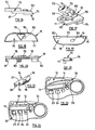
- the blade spring 14, or as described, a pair of such springs are fitted into the body part 10 generally as shown in Figure 23 with the bent leg portion of the or each spring being received in the undercut 33, the or each spring extending between the wall 19 and the extension part 32 with the end or ends of the spring or springs engaging against the flat unrecessed exterior side of the main body portion 12a of the holder 12 so as normally to bias the holder in a direction outwardly of the body as shown in Figure 23 and also in Figure 25, Figure 23 showing the holder engaged with the body part 10 and Figure 25 showing the holder engaged with the body part 11.
- the holder is prevented from further outwards movement by, for example, an end part of the holder remote from its hole 46 engaging with the wall 18 as well as the inner ends of the openings 68 and 69 engaging with the associated upstanding projections at the openings 21 and 22 if both are provided.
- the projection 39 can act as a stop to engage against the inside of the flat unrecessed wall of the part 12a as previously described. All three projections 38, 39, and 45 can act as stops to engage the part 12a to restrict inwards movement of the holder 12 in the opposite direction against the spring bias, although in view of the spring bias, this extreme inward position may not be attainable.
- stops on the body part 10 are concerned, these, as shown in Figure 24, can be the spring itself which in turn engages against the body part 10, as well as the upstanding projections at the openings 20, 21 and 22.
- the opening 20 is for the insertion into and through the tool body of a cable, which can be single or multi-core, with the core being of any particular form.
- cable inserted through this opening 20, and extending through its associated aligned opening 35 will be cut through, i.e. severed, so as to separate the cable into two parts.
- the central opening 21 is for trimming and/or stripping the sleeve or outer plastics cover of such a type of cable mentioned, and again the opening is relatively large to permit insertion of this type of cable.
- the smallest opening 22 is for stripping an insulating or other sleeve from an individual conductor and is thus primarily intended for use with individual sleeved conducting wires, i.e. cores of a single or multi-core cable. Again the depth of cut adjustment is actuable at this opening.
- the cable can be inserted into the holes described and passed through the body by way of the aligned holes respectively in the body part 11, but even if the cable or core is not fully inserted through the body, the openings in the body part 11 are still desirable to allow the stripped sleeve or insulation to fall or to be removed from the body, generally automatically on completion of the stripping operation.
- holes for cable reception need not extend completely through the body.
- indicia/pictures illustrating the intended use of each of the three openings would normally be provided on the front surface of the body part 10. Moreover adjacent the position of the operating button 16 at the 'bottom' of the front surface of body part 10 the two extreme positions of adjustment of the anvil member would be illustrated by an indication as to where the tip of the arrow head projection 79 should be disposed, one position, corresponding to the button being at one end of its allowed movement, corresponding to a cut depth, for example, for three-core cable, and the other position, corresponding to the button being at its other end of its travel, for example, for co-axial cable.
- the adjustment may be such that only one extreme position or the other can be used, but alternatively it may be possible for the button to be held in any desired position between said two extremes so as to provide a continuously variable degree of selection for the depth of cut. In other words the button might be lockable, effectively by the ratchet, in any adjusted position.
- the cable or core is then inserted as required into the selected hole, as previously described.
- the holder 12 is then released and the spring bias will force it outwardly so that the sharpened edge of the blade will engage against the periphery of the inserted cable/core.
- the pulling out may in itself both effect the stripping of the outer sleeve and also effect twisting together of the very thin individual conductor wires previously enclosed by the outer sleeving, this being the type of arrangement with, for example, each core in a domestic three-pin plug.
- the cable can be removed from opening 21 and then bent slightly at the cut mark so that if the depth of cut is sufficient, the outer insulation will break through, and can be removed.
- the cutting force is supplied by the energy stored in the blade spring when it is deformed.
- the cutting force thus depends on the strength of the spring. Although normally this force is insufficient to cut the cable either partially or certainly wholly without the relative rotation referred to (which makes the force more effective), the force could be made sufficient so as to make rotation unnecessary, by the use of sufficiently strong spring means.
- Figures 25 and 26 show in effect the same operation as Figures 23 and 24, but without illustrating the blade springs 14.
- Figure 25 shows the depth of cut adjusted by means of the button 16 so that the maximum amount of the sharpened cutting edge of the blade 13 is available for cutting in that the anvil is moved away from the front of this sharpened blade surface.
- the alternative extreme adjusted position is shown in Figure 27 where the button is at its other extreme end of travel and, for the openings 21 and 22, the anvil shrouds a substantial part of the sharpened edge of the blade.
- the anvil would, in practice, leave at least a small portion uncovered to effect a limited cutting of the inserted core/cable.
- maximum depth of cut would be used, for example in stripping the outer cable from conventional domestic flex, such as that used with a two or three-pin plug.
- a reduced depth of cut would normally be used with thinner sleeved cable, for example co-axial cable such as the form used in computer cabling.
- this first embodiment of the invention has been described as incorporating the depth of cut adjustment means, such means could of course be omitted if required.
- this depth of cut adjustment is considered an inventive feature in its own right and thus could be used independently of the other inventive feature or features of this first embodiment, and could be included with or omitted from the second embodiment, to be described.
- pressure relief means are provided for relieving the main spring pressure on the inserted conductor. Without the relief means a single small wire may be gripped so firmly that there is a danger of the cutting blade just clamping on to the wire, and twisting into a kink or knot, as if it were held in pliers and turned. In such a case there would not be the required relative rotation and resultant stripping of the wire.
- the associated upstanding guide projection at the one side of the opening 22 can be omitted and instead the described recess 27 provided.
- this second embodiment of the invention there is received in this recess the pressure relief insert 83 shown in Figures 28 to 30.
- This is in the form of an injection moulded one piece plastics member having a generally rectangular base 84 which is a tight fit in the recess 27. From Figures 28 to 30, it can be seen that from the centre of its upper face, a slightly tapering, generally rectangular projection 85 is upstanding, this, in use, extending through openings 69 and 54 to the inner surface of the body part 11, i.e. acting in the same manner as the guide projection it replaces at opening 22.
- the projection is recessed to continue upwards the projection of part of a circular hole 86 formed at the foot of the projection through the base 84 as shown best in Figure 30. It can be seen that on the underside of the base the hole 86 hole is countersunk.
- the insert 83 fits in the recess 27 so that this hole 86 is over and aligned with the hole 22 for the passage of a thin core as described. In use, part of the inserted cable is received in the recessed part of the projection corresponding in shape to said part of hole 86.
- the base is formed with a flexible portion 87 formed by a pair of interconnected arms, the portion 87 terminating in a tip 88 which engages the narrower end of the slot 27 adjacent the longer side of the body part 10 which is open.
- the insert in effect acts as a plastics material spring to allow sliding movement of the insert 83 by compression of the flexible portion 87, if required, in order to reduce the 'pinch' on the cable so as to allow cutting to take place as required to enable the stripping of the wire as described.
- This pressure relieving insert is itself believed to be inventive alone and or in combination with one or both of the other inventive features described and identified herein.
- the holder 12 could alternatively be linearly movable relative to the tool body. Moreover the holder 12 could be biased to its release position instead of to its position where the cutting blade obstructs the body openings for cable insertion. Resilient means other than a blade spring could be used to bias the holder 12 to its cable release or cable engagement position. Clearly the anvil member 15 and button 16 could have their angled slot and projection respectively reversed, i.e. the slot being in the button.
Landscapes
- Knives (AREA)
- Removal Of Insulation Or Armoring From Wires Or Cables (AREA)
Claims (14)
- Ein in Verbindung mit einem Kabel benutzbares Handwerkzeug mit einem Hauptkörper (10, 11), der ein Loch (20, 21, 22) zum Einführen eines Kabels aufweist, mit einem von einem Halter (12) getragenen Schneidelement (13), das relativ zu dem Hauptkörper (10, 11) in eine erste Stellung, in der das Schneidelement (13) das Loch (20, 21, 22) zum Einführen eines Kabels in das Loch freigibt, und in eine zweite Stellung bewegbar ist, in der sich das Schneidelement (13) über das Loch (20, 21, 22) erstreckt, mit einer Feder (14) zum Vorspannen des Halters (12) in die zweite Stellung, so dass der Halter (12) im Gebrauch entgegen der Kraft der Feder in die erste Stellung überführt werden kann, in der das Einstecken des Kabels in das Loch möglich ist, wobei das eingesteckte Kabel mit dem Schneidelement beim Lösen des Drucks gegen die Kraft der vorgespannten Feder in Kontakt kommt, so dass mindestens bei einer Relativbewegung zwischen dem in dem Loch aufgenommenen Kabel und dem Schneidelement ein Schnitt in das Kabel entsteht, wobei das Schneidelement ein Messer mit einer scharfen Längskante aufweist, und mit einer Einrichtung zum Einstellen der Schnitttiefe zwischen dem Schneidelement und dem in dem Loch aufgenommenen Kabel, dadurch gekennzeichnet, dass die Einrichtung zum Einstellen der Schnitttiefe ein gegenüber der Längskante vor- und zurückbewegliches Teil (15) zum Freigeben eines größeren oder kleineren Teils des Schneidelements und damit zum Erzeugen einer größeren oder kleineren Schnitttiefe an einem in dem Loch aufgenommenen Kabel aufweist, und dass der Halter (12) so angeordnet ist, dass er sich in einer Richtung nach innen relativ zu dem Hauptkörper (10, 11) bewegt, wenn er in die erste Stellung überführt wird, und er sich in einer Richtung nach außen relativ zu dem Hauptkörper (10, 11) bewegt, wenn er in die zweite Stellung überführt wird, wobei die Feder (14) so angeordnet ist, dass sie den Halter (12) nach außen vorspannt.
- Ein Handwerkzeug nach Anspruch 1, dadurch gekennzeichnet, dass das bewegliche Teil (15) eine Fläche (68a, 69a) aufweist, die mit dem Kabel in Kontakt kommt, wenn die durch die Einrichtung zum Einstellen der Schnitttiefe eingestellte Tiefe des Schnitts erreicht wird.
- Ein Handwerkzeug nach Anspruch 1 oder 2, dadurch gekennzeichnet, dass die Einrichtung zum Einstellen der Schnitttiefe einen manuell betätigbaren Schieber (16) aufweist, dessen Gleitbewegung in die Einstellbewegung des Teils (15) umgeformt wird, das einen größeren oder kleineren Teil des Schneidelements (13) freigibt, wobei der Schieber für eine manuelle Betätigung außerhalb des Hauptkörpers des Handwerkzeugs zumindest dann zugänglich ist, wenn kein Kabel in dem Loch eingesetzt und ein Teil des Halters nach außen aus dem Hauptkörper belastet ist.
- Ein Handwerkzeug nach Anspruch 3, dadurch gekennzeichnet, dass die Gleitbewegung des Schiebers (16) linear ausgebildet und durch mindestens einen in dem Gleitweg angeordneten Vorsprung (81, 82) geführt ist.
- Ein Handwerkzeug nach Anspruch 4, dadurch gekennzeichnet, dass das Teil (15) in dem Halter in einer linearen Bewegung geführt ist, die im Wesentlichen quer zu der linearen Bewegung des Schiebers (16) angeordnet ist.
- Ein Handwerkzeug nach Anspruch 5, dadurch gekennzeichnet, dass der Schieber (16) und das Teil (15) einen Vorsprung (80) und einen im Winkel angeordneten Schlitz (74) aufweisen, in den der Vorsprung (80) eingreift, oder umgekehrt, wobei der Winkel des Schlitzes relativ zur Gleitrichtung des Vorsprungs so ausgebildet ist, dass die relative im Wesentlichen quer erfolgende Bewegung infolge der manuellen Einstellung des Schiebers (16) in dem Halter bereitgestellt wird.
- Ein Handwerkzeug nach Anspruch 6, dadurch gekennzeichnet, dass die betreffenden, miteinander in Kontakt kommenden Flächen an dem Vorsprung (80) und an dem Schlitz (74) mit Verzahnungen versehen sind.
- Ein Handwerkzeug nach einem der vorangehenden Ansprüche, dadurch gekennzeichnet, dass der Hauptkörper von einem ersten und einem zweiten Teilkörper (10, 11) gebildet wird, die miteinander verbunden sind und so einen Innenraum bilden, in dem das Schneidelement (13) angeordnet ist, wobei die Löcher (20, 21, 22) zur Aufnahme eines Kabels durch fluchtende Durchbrechungen in dem ersten und zweiten Teilkörper gebildet werden.
- Ein Handwerkzeug nach Anspruch 8, dadurch gekennzeichnet, dass der Halter (15) in dem Hauptkörper schwenkbar gelagert ist.
- Ein Handwerkzeug nach Anspruch 8, dadurch gekennzeichnet, dass der Halter (15) einen hohlen zylindrischen Endbereich (47, 48) aufweist, der zur schwenkbaren Verbindung des Halters mit dem Hauptkörper beidseitig zur Aufnahme koaxialer kreisförmiger Öffnungen (40) in den beiden Teilkörpern ausgebildet ist.
- Ein Handwerkzeug nach einem der vorangehenden Ansprüche, dadurch gekennzeichnet, dass in dem Hauptkörper ein weiteres Loch (20) zur Aufnahme eines Kabels vorgesehen ist, dass die Einrichtung zur Einstellung der Schnitttiefe (15) relativ zu dem Loch (21) in dem Hauptkörper, nicht jedoch relativ zu dem weiteren Loch (20) betätigbar ist, das zum Durchschneiden des Kabels vorgesehen ist.
- Ein Handwerkzeug nach Anspruch 11, dadurch gekennzeichnet, dass noch ein weiteres Loch (22) zur Aufnahme des Kabels in dem Hauptkörper vorgesehen ist, und dass die Einrichtung zur Einstellung der Schnitttiefe relativ zu diesem weiteren Loch (22) betätigbar ist.
- Ein Handwerkzeug nach einem der vorangehenden Ansprüche, dadurch gekennzeichnet; dass in dem Hauptkörper eine Einrichtung (84) zur Verminderung der Schnittkraft des vorgespannten Scheidelements auf das in das Loch im Hauptkörper eingesetzte Kabel vorgesehen ist.
- Ein Handwerkzeug nach Anspruch 13, dadurch gekennzeichnet, dass die Einrichtung zur Verminderung der Schnittkraft einen nachgiebigen Bereich (87) aufweist, der infolge einer Gleitbewegung eines weiteren Teils der Einrichtung durch eine übermäßige Schnittkraft auf das eingesetzte Kabel zusammendrückbar ist.
Applications Claiming Priority (2)
| Application Number | Priority Date | Filing Date | Title |
|---|---|---|---|
| GB9707211 | 1997-04-09 | ||
| GBGB9707211.0A GB9707211D0 (en) | 1997-04-09 | 1997-04-09 | Hand tool |
Publications (3)
| Publication Number | Publication Date |
|---|---|
| EP0871270A2 EP0871270A2 (de) | 1998-10-14 |
| EP0871270A3 EP0871270A3 (de) | 1999-06-16 |
| EP0871270B1 true EP0871270B1 (de) | 2005-10-26 |
Family
ID=10810542
Family Applications (1)
| Application Number | Title | Priority Date | Filing Date |
|---|---|---|---|
| EP98301893A Expired - Lifetime EP0871270B1 (de) | 1997-04-09 | 1998-03-13 | Handwerkzeug |
Country Status (8)
| Country | Link |
|---|---|
| US (1) | US6058606A (de) |
| EP (1) | EP0871270B1 (de) |
| JP (1) | JPH10290505A (de) |
| CN (1) | CN1197701A (de) |
| AU (1) | AU5965198A (de) |
| CA (1) | CA2234312A1 (de) |
| DE (1) | DE69831996T2 (de) |
| GB (1) | GB9707211D0 (de) |
Families Citing this family (30)
| Publication number | Priority date | Publication date | Assignee | Title |
|---|---|---|---|---|
| WO2000033430A1 (en) * | 1998-11-30 | 2000-06-08 | The Siemon Company | Preparation tool for shielded cables |
| SE522838C2 (sv) * | 2001-12-19 | 2004-03-09 | Pressmaster Ab | Anordning för skalning av kabel |
| USD481286S1 (en) | 2001-12-19 | 2003-10-28 | Pressmaster Ab | Cable stripping tool |
| USD481607S1 (en) | 2001-12-19 | 2003-11-04 | Pressmaster Ab | Cable stripping tool |
| US6813981B2 (en) | 2002-11-30 | 2004-11-09 | Bellsouth Intellectual Property Corporation | Apparatus and method for cutting cables and wires |
| US20040159197A1 (en) * | 2003-02-13 | 2004-08-19 | Kevin Forsberg | Apparatus and method for cutting cables and wires |
| DE20302948U1 (de) * | 2003-02-24 | 2004-07-22 | Weidmüller Interface GmbH & Co. KG | Entmantelungswerkzeug |
| US7000322B2 (en) * | 2003-08-08 | 2006-02-21 | Ideal Industries, Inc. | Blade assembly |
| US7137204B2 (en) * | 2004-09-22 | 2006-11-21 | Wiste Rodney J | Wire tool system and method |
| US20060163280A1 (en) * | 2005-01-24 | 2006-07-27 | Accurate Concepts, Inc. | Dispensing tube opener |
| US20070175048A1 (en) * | 2006-01-31 | 2007-08-02 | Tycohealthcare Group Lp | Medical apparatus for cutting medical tubes |
| USD660431S1 (en) | 2006-05-02 | 2012-05-22 | Tyco Healthcare Group Lp | Cutting apparatus for medical tubes |
| US8109002B2 (en) * | 2007-05-01 | 2012-02-07 | Sog Specialty Knives And Tools, Llc | Wire stripping back bar knife |
| US20080271255A1 (en) * | 2007-05-01 | 2008-11-06 | Spencer Frazer | Knife wire stripping tool |
| US7665389B2 (en) * | 2007-05-01 | 2010-02-23 | SOG Specialty Knives & Tools LLC | Multitool with wire stripping element |
| US20080271258A1 (en) * | 2007-05-01 | 2008-11-06 | Spencer Frazer | Wire stripping knife with arm stripping element |
| DE102007038626B3 (de) | 2007-08-16 | 2008-10-09 | Wezag Gmbh Werkzeugfabrik | Zange zum Abisolieren eines Kabels |
| TWM389388U (en) * | 2009-12-16 | 2010-09-21 | Jetool Corp | Wire and cable stripper |
| USD626812S1 (en) * | 2010-01-13 | 2010-11-09 | Emerson Electric Co. | Pipe cutter |
| US8453332B2 (en) * | 2011-07-08 | 2013-06-04 | Elbex Video Ltd. | Hand tool and method for cutting plastic fiber optic cable without error |
| DE102012215460A1 (de) * | 2012-08-31 | 2014-03-06 | Robert Bosch Gmbh | Schneidstrangsegment |
| USD749391S1 (en) * | 2014-10-10 | 2016-02-16 | Southwire Company, Llc | Wire stripper |
| GB2545883A (en) * | 2015-11-04 | 2017-07-05 | Hellermann Tyton Ltd | A cable stripping tool for electrical cables |
| WO2017172416A1 (en) | 2016-03-27 | 2017-10-05 | Southwire Company, Llc | Cable stripper |
| USD896606S1 (en) * | 2017-05-04 | 2020-09-22 | Siang Syuan Fu Enterprise Co., Ltd. | Cutter |
| US20190031923A1 (en) | 2017-07-26 | 2019-01-31 | 3M Innovative Properties Company | Backing for adhesive tape with thermal resistance |
| CN109390877B (zh) * | 2017-08-07 | 2024-11-12 | 杭州巨星科技股份有限公司 | 一种盒式剥线器 |
| US11646554B2 (en) * | 2021-03-10 | 2023-05-09 | Consolidated Edison Company Of New York, Inc. | Hook knife with integral guard |
| USD998439S1 (en) * | 2022-01-06 | 2023-09-12 | Siang Syuan Fu Enterprise Co., Ltd. | Cutter |
| USD999040S1 (en) * | 2022-01-06 | 2023-09-19 | Siang Syuan Fu Enterprise Co., Ltd. | Cutter |
Family Cites Families (16)
| Publication number | Priority date | Publication date | Assignee | Title |
|---|---|---|---|---|
| US2995052A (en) * | 1958-09-17 | 1961-08-08 | Jack F Funcik | Wire stripper and cutter |
| US3257722A (en) * | 1965-04-20 | 1966-06-28 | Earle M Caine | Stripper knife |
| GB1345976A (en) * | 1971-07-07 | 1974-02-06 | Bieganski Z | Stripping tools |
| US3881249A (en) * | 1974-06-05 | 1975-05-06 | Ideal Ind | Cable stripper |
| US4070930A (en) * | 1976-09-03 | 1978-01-31 | Ideal Industries Inc. | Wire stripper |
| US4366619A (en) * | 1980-12-29 | 1983-01-04 | Zdzislaw Bieganski | Cable stripper |
| US4426778A (en) * | 1981-12-14 | 1984-01-24 | Avco Corporation | Device for stripping wire and cable |
| DE3214208A1 (de) * | 1982-04-17 | 1983-10-20 | Kaiser GmbH & Co KG, 5885 Schalksmühle | Abmantelzange |
| GB2173958B (en) * | 1985-04-16 | 1988-08-03 | Egerton A C Ltd | Coxial cable stripper |
| US4829671A (en) * | 1987-11-09 | 1989-05-16 | Cheng Yin Ho | Copper cable wire peeler |
| US4805302A (en) * | 1987-11-17 | 1989-02-21 | Rostra Tool Company | Wire stripper |
| GB2226461B (en) * | 1988-12-22 | 1993-05-26 | Zdzislaw Bieganski | Coaxial cable stripper |
| GB2231732A (en) * | 1989-04-29 | 1990-11-21 | Barry Peter Liversidge | Wire stripping tool |
| US5036734A (en) * | 1989-10-25 | 1991-08-06 | Ben Hughes Communication Products Co. | Cable stripping tool |
| US5398413A (en) * | 1994-04-13 | 1995-03-21 | Chen; Ching-Jen | Coaxial cable stripper |
| DE19543390C1 (de) * | 1995-11-21 | 1997-01-09 | Weidmueller Interface | Abisoliergerät |
-
1997
- 1997-04-09 GB GBGB9707211.0A patent/GB9707211D0/en active Pending
-
1998
- 1998-03-13 EP EP98301893A patent/EP0871270B1/de not_active Expired - Lifetime
- 1998-03-13 DE DE69831996T patent/DE69831996T2/de not_active Expired - Fee Related
- 1998-03-24 JP JP10075431A patent/JPH10290505A/ja not_active Withdrawn
- 1998-03-26 AU AU59651/98A patent/AU5965198A/en not_active Abandoned
- 1998-04-03 US US09/054,824 patent/US6058606A/en not_active Expired - Fee Related
- 1998-04-07 CA CA002234312A patent/CA2234312A1/en not_active Abandoned
- 1998-04-08 CN CN98106359A patent/CN1197701A/zh active Pending
Also Published As
| Publication number | Publication date |
|---|---|
| JPH10290505A (ja) | 1998-10-27 |
| GB9707211D0 (en) | 1997-05-28 |
| EP0871270A2 (de) | 1998-10-14 |
| CN1197701A (zh) | 1998-11-04 |
| EP0871270A3 (de) | 1999-06-16 |
| AU5965198A (en) | 1998-10-15 |
| DE69831996D1 (de) | 2005-12-01 |
| DE69831996T2 (de) | 2006-04-20 |
| US6058606A (en) | 2000-05-09 |
| CA2234312A1 (en) | 1998-10-09 |
Similar Documents
| Publication | Publication Date | Title |
|---|---|---|
| EP0871270B1 (de) | Handwerkzeug | |
| US6128976A (en) | Single drop trimmer | |
| EP1484824B1 (de) | Vorrichtung zum Anschliessen von Kabeln sowie Verfahren | |
| US4640009A (en) | Co-axial cable stripping tool and end portion preparation method | |
| US6253641B1 (en) | Single drop trimmer with limited cartridge release | |
| US6872090B2 (en) | Cable terminating apparatus and method | |
| US6138362A (en) | Cable stripper | |
| US4805302A (en) | Wire stripper | |
| CA1234481A (en) | Communication plug connection tool | |
| US4407174A (en) | Tool for stripping electrical conductors | |
| EP0791993B1 (de) | Entmantelungswerkzeug für elektrischer draht | |
| EP0369957A2 (de) | Kabelabmantelungswerkzeug | |
| US4341134A (en) | Tool for stripping insulating covering | |
| US3447172A (en) | Electrician's tool | |
| JPS6133329B2 (de) | ||
| EP1236255B1 (de) | Drahtentmantelungsgerät | |
| US4047297A (en) | Precision small wire stripper | |
| CN218632744U (zh) | 一种自适应剥线的网线钳 | |
| US4667406A (en) | Cable end stripping device | |
| IE980689A1 (en) | Electrical cable insulation cutter | |
| JP3243024B2 (ja) | スロットの口出し機 | |
| KR200369304Y1 (ko) | 전기 케이블 탈피기 | |
| GB2215143A (en) | Wire stripper | |
| US20040159197A1 (en) | Apparatus and method for cutting cables and wires | |
| JP2746534B2 (ja) | 被覆ケーブルの加工工具 |
Legal Events
| Date | Code | Title | Description |
|---|---|---|---|
| PUAI | Public reference made under article 153(3) epc to a published international application that has entered the european phase |
Free format text: ORIGINAL CODE: 0009012 |
|
| AK | Designated contracting states |
Kind code of ref document: A2 Designated state(s): DE FR GB |
|
| AX | Request for extension of the european patent |
Free format text: AL;LT;LV;MK;RO;SI |
|
| PUAL | Search report despatched |
Free format text: ORIGINAL CODE: 0009013 |
|
| AK | Designated contracting states |
Kind code of ref document: A3 Designated state(s): AT BE CH DE DK ES FI FR GB GR IE IT LI LU MC NL PT SE |
|
| AX | Request for extension of the european patent |
Free format text: AL;LT;LV;MK;RO;SI |
|
| 17P | Request for examination filed |
Effective date: 19990813 |
|
| AKX | Designation fees paid |
Free format text: DE FR GB |
|
| 17Q | First examination report despatched |
Effective date: 20030417 |
|
| GRAP | Despatch of communication of intention to grant a patent |
Free format text: ORIGINAL CODE: EPIDOSNIGR1 |
|
| GRAS | Grant fee paid |
Free format text: ORIGINAL CODE: EPIDOSNIGR3 |
|
| GRAA | (expected) grant |
Free format text: ORIGINAL CODE: 0009210 |
|
| AK | Designated contracting states |
Kind code of ref document: B1 Designated state(s): DE FR GB |
|
| REG | Reference to a national code |
Ref country code: GB Ref legal event code: FG4D |
|
| REF | Corresponds to: |
Ref document number: 69831996 Country of ref document: DE Date of ref document: 20051201 Kind code of ref document: P |
|
| ET | Fr: translation filed | ||
| PLBE | No opposition filed within time limit |
Free format text: ORIGINAL CODE: 0009261 |
|
| STAA | Information on the status of an ep patent application or granted ep patent |
Free format text: STATUS: NO OPPOSITION FILED WITHIN TIME LIMIT |
|
| PG25 | Lapsed in a contracting state [announced via postgrant information from national office to epo] |
Ref country code: DE Free format text: LAPSE BECAUSE OF NON-PAYMENT OF DUE FEES Effective date: 20061003 |
|
| 26N | No opposition filed |
Effective date: 20060727 |
|
| REG | Reference to a national code |
Ref country code: FR Ref legal event code: ST Effective date: 20061130 |
|
| PG25 | Lapsed in a contracting state [announced via postgrant information from national office to epo] |
Ref country code: FR Free format text: LAPSE BECAUSE OF NON-PAYMENT OF DUE FEES Effective date: 20060331 |
|
| PGFP | Annual fee paid to national office [announced via postgrant information from national office to epo] |
Ref country code: GB Payment date: 20080926 Year of fee payment: 11 |
|
| GBPC | Gb: european patent ceased through non-payment of renewal fee |
Effective date: 20090313 |
|
| PG25 | Lapsed in a contracting state [announced via postgrant information from national office to epo] |
Ref country code: GB Free format text: LAPSE BECAUSE OF NON-PAYMENT OF DUE FEES Effective date: 20090313 |