EP0870945A1 - Embrayage à limitation de couple - Google Patents
Embrayage à limitation de couple Download PDFInfo
- Publication number
- EP0870945A1 EP0870945A1 EP98105709A EP98105709A EP0870945A1 EP 0870945 A1 EP0870945 A1 EP 0870945A1 EP 98105709 A EP98105709 A EP 98105709A EP 98105709 A EP98105709 A EP 98105709A EP 0870945 A1 EP0870945 A1 EP 0870945A1
- Authority
- EP
- European Patent Office
- Prior art keywords
- ring
- torque transmission
- coupling
- drivers
- radially
- Prior art date
- Legal status (The legal status is an assumption and is not a legal conclusion. Google has not performed a legal analysis and makes no representation as to the accuracy of the status listed.)
- Ceased
Links
- 230000008878 coupling Effects 0.000 claims abstract description 79
- 238000010168 coupling process Methods 0.000 claims abstract description 79
- 238000005859 coupling reaction Methods 0.000 claims abstract description 79
- 230000005540 biological transmission Effects 0.000 claims description 69
- 241000282472 Canis lupus familiaris Species 0.000 abstract 7
- 230000013011 mating Effects 0.000 abstract 1
- 239000000969 carrier Substances 0.000 description 6
- 230000033001 locomotion Effects 0.000 description 6
- 238000006073 displacement reaction Methods 0.000 description 2
- 230000002349 favourable effect Effects 0.000 description 2
- 238000007654 immersion Methods 0.000 description 2
- 206010010774 Constipation Diseases 0.000 description 1
- 230000006835 compression Effects 0.000 description 1
- 238000007906 compression Methods 0.000 description 1
- 238000005553 drilling Methods 0.000 description 1
- 230000005284 excitation Effects 0.000 description 1
- 210000003746 feather Anatomy 0.000 description 1
- 238000004519 manufacturing process Methods 0.000 description 1
- 230000000149 penetrating effect Effects 0.000 description 1
- 230000007306 turnover Effects 0.000 description 1
Images


Classifications
-
- F—MECHANICAL ENGINEERING; LIGHTING; HEATING; WEAPONS; BLASTING
- F16—ENGINEERING ELEMENTS AND UNITS; GENERAL MEASURES FOR PRODUCING AND MAINTAINING EFFECTIVE FUNCTIONING OF MACHINES OR INSTALLATIONS; THERMAL INSULATION IN GENERAL
- F16D—COUPLINGS FOR TRANSMITTING ROTATION; CLUTCHES; BRAKES
- F16D43/00—Automatic clutches
- F16D43/02—Automatic clutches actuated entirely mechanically
- F16D43/20—Automatic clutches actuated entirely mechanically controlled by torque, e.g. overload-release clutches, slip-clutches with means by which torque varies the clutching pressure
- F16D43/202—Automatic clutches actuated entirely mechanically controlled by torque, e.g. overload-release clutches, slip-clutches with means by which torque varies the clutching pressure of the ratchet type
- F16D43/204—Automatic clutches actuated entirely mechanically controlled by torque, e.g. overload-release clutches, slip-clutches with means by which torque varies the clutching pressure of the ratchet type with intermediate balls or rollers
- F16D43/208—Automatic clutches actuated entirely mechanically controlled by torque, e.g. overload-release clutches, slip-clutches with means by which torque varies the clutching pressure of the ratchet type with intermediate balls or rollers moving radially between engagement and disengagement
-
- F—MECHANICAL ENGINEERING; LIGHTING; HEATING; WEAPONS; BLASTING
- F16—ENGINEERING ELEMENTS AND UNITS; GENERAL MEASURES FOR PRODUCING AND MAINTAINING EFFECTIVE FUNCTIONING OF MACHINES OR INSTALLATIONS; THERMAL INSULATION IN GENERAL
- F16D—COUPLINGS FOR TRANSMITTING ROTATION; CLUTCHES; BRAKES
- F16D43/00—Automatic clutches
- F16D43/02—Automatic clutches actuated entirely mechanically
- F16D43/20—Automatic clutches actuated entirely mechanically controlled by torque, e.g. overload-release clutches, slip-clutches with means by which torque varies the clutching pressure
- F16D43/202—Automatic clutches actuated entirely mechanically controlled by torque, e.g. overload-release clutches, slip-clutches with means by which torque varies the clutching pressure of the ratchet type
- F16D43/2028—Automatic clutches actuated entirely mechanically controlled by torque, e.g. overload-release clutches, slip-clutches with means by which torque varies the clutching pressure of the ratchet type with at least one part moving radially between engagement and disengagement
-
- F—MECHANICAL ENGINEERING; LIGHTING; HEATING; WEAPONS; BLASTING
- F16—ENGINEERING ELEMENTS AND UNITS; GENERAL MEASURES FOR PRODUCING AND MAINTAINING EFFECTIVE FUNCTIONING OF MACHINES OR INSTALLATIONS; THERMAL INSULATION IN GENERAL
- F16D—COUPLINGS FOR TRANSMITTING ROTATION; CLUTCHES; BRAKES
- F16D43/00—Automatic clutches
- F16D43/02—Automatic clutches actuated entirely mechanically
- F16D43/22—Automatic clutches actuated entirely mechanically controlled by both speed and torque
Definitions
- the invention relates to a clutch for torque limitation, especially in the drive train for driving agricultural Devices or machines with a coupling hub and coaxial with a bearing bore arranged around it and relatively rotatable thereon mounted coupling sleeve, with drivers, each of which in a recess of the coupling hub radially with respect to a Axis of rotation between a torque transmission position and a switch position is adjustable and each driver at least has a button and a torque transfer surface has, the latter in the torque transmission position on a torque transmission surface in the bearing bore the coupling sleeve attacks with one in the direction the axis of rotation on one side of the driver adjustable Switch ring that corresponds to the number of buttons Number of support surfaces for support on the buttons the driver has and in the direction of the axis of rotation is spring loaded and the driver in the radially outward shifted torque transmission position urges and the opposite the force of the spring an adjustment of the driver in the radially inner switch-off position when a predetermined one is exceeded Allows torque.
- GB-PS 849 516 there is a clutch for torque limitation described.
- the inner end of the driver has buttons on, with corresponding support surfaces two on one Bolted shift rings in the torque transmission position be pushed outward with respect to the axis of rotation.
- Each Switch ring is assigned a compression spring.
- Clamping bolt which is arranged in the bore of the coupling hub is.
- the drivers slide into their radial inner switch-off position. They are supported in the bearing bore until they continue in circulation against those formed by rollers Torque transmission surfaces come into contact again. The happens again with each round and leads to blows Signs of wear on the drivers and the corresponding Rollers forming torque transmission surfaces.
- An overload clutch is described in DE-AS 12 16 622, in which the coupling hub is provided with circumferentially distributed pockets is in which driver in the form of balls or at the ends conical rollers are added which are axially related springs acting on the longitudinal axis of the coupling hub for engaging in Correspondingly circumferentially distributed depressions in the inner surface are applied to the coupling sleeve. They occur when overloaded from the recesses of the coupling sleeve, however, are constantly through the springs to return to the next recess with relative rotation of the coupling hub and coupling sleeve.
- the US-PS 4 744 447 describes an overload clutch in which Driver radially guided in openings of a coupling sleeve are and for engagement in recesses of a clutch hub sideways, i.e. axially arranged with respect to the coupling longitudinal axis and spring-loaded switching rings are caused.
- the drivers with buttons and the switching rings with Provide support surfaces.
- the drivers emerge from the Recesses and are held in this switch-off position.
- a flyweight is provided, that of the shift ring to which it is assigned, in the torque transmission position held in a radially inner position is and in case of overload by moving the Switching rings against the force of the spring acting on it Movement in a switch-off position are released, in which they prevent the shift ring from entering the torque transmitting position return until a predetermined shift speed is undercut.
- the invention is therefore based on the object of a clutch to create torque limitation at which a complete and simultaneous disengagement or engagement of the drivers in the switch-off position or the torque transmission position guaranteed is.
- This object is achieved in that the driver with its end face facing away from the switching ring a support ring flat and radial with respect to the axis of rotation are adjustable supported.
- the advantage of this training is that the driver is safe radially adjusted to the switch-off or torque transmission position without tipping and thus a partial inclusion or Shutdown can occur.
- the contact area between the Support ring and the driver is relatively large and thus prevents sure a tipping.
- the support ring is fixed on the coupling hub in the direction of the axis of rotation.
- the support ring is preferably between a side surface of the clutch hub removed from the shift ring and a securing element fixed to the coupling hub held.
- a paragraph is provided on which the support ring is pushed on and against the side surface the coupling hub creates, with the securing element in Shape of a circlip and in a groove in the heel is recorded.
- each driver is in shape a bar designed, one end face flat on the support ring abuts and that between this end face and its the Switching ring opposite end face radially outside the torque transmission surface and the radially inside the button or buttons.
- One of the faces of everyone Driver thus serves for radial guidance on a corresponding one Sliding surface of the support ring.
- the drivers are cylindrical Designed roles.
- the lateral surface forms the torque transmission surface.
- One end face lies flat Support ring on and the other end face that the switching ring opposite, has the buttons.
- a particularly favorable application results for a clutch in which at least one centrifugal weight is assigned to the switching ring is that radial with respect to the axis of rotation between a radial outer shutdown position and a radially inner torque transmission position is adjustable, it is through the switching ring held against displacement in the torque transmission position is, so that when the predetermined torque is exceeded from the switching ring to the adjustment to the switch-off position is released.
- the centrifugal weight prevents a reset of the switching ring in the torque transmission position as long a predetermined switching speed is exceeded.
- the centrifugal weight becomes to its inner position corresponding to the torque transmission position Position in which it is approximated to the axis of rotation is returned. This releases the switching ring, so that it the drivers acted in such a way that they are supported on the support ring to their torque transmission position, i.e. their radial position moved to the outside can be transferred again.
- the axial movement of the switching ring is limited. This comes when the drivers are in their torque transmission position have taken axially against the coupling hub to the system. A design can be selected in which the Drivers are held in this position without force and this only then adjust the switching ring against the force of the spring, when torque is applied.
- Particularly favorable conditions with regard to the transfer to the torque transmission position or support in the switch-off position is achieved in that the driver in each case first and second buttons and the switching ring each first and have second support surfaces, the first buttons and the first support surfaces in the torque transmission position the driver and the second buttons and second Support surfaces lie against each other in the switch-off position.
- the first driver buttons and the first one are used Support surface of the shift ring for support in the torque transmission position and the second buttons of the carriers and the second support surface of the switching ring for support in the switch-off position.
- the set torque is radial Dodge the driver inside so that the force exerted by the spring is exerted on the drivers as a radial component, is reduced. This means that there is less restart suddenly and with less force. Hereby a positive influence on wear behavior is exerted. Furthermore, there is less vibration excitation.
- the arrangement of the second buttons and the as second support surface serving so that the Switching ring is kept at an axial distance from the centrifugal weight, when an overload occurs and thus the flyweight is released.
- An axial play is provided that even if the limit speed at which the centrifugal weight after Exceeding the specified limit torque is shifted to the outside an axial range of motion between the switching ring and allows centrifugal weight.
- the drivers can be due the force of the axially acting spring by a small amount Dimension radially outwards towards the torque transmission position to be moved, under the influence of the course the second buttons or support areas.
- Such Function is also guaranteed when there are no second ones Buttons or support surfaces are available.
- the centrifugal weight is preferably made radial by spring force applied and includes the inner torque transmission position several fleeing segments.
- flyweight and the Switch ring retaining surfaces which are used to axially support the switch ring serve against the centrifugal weight.
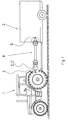
- the tractor 1 with the attached device 2 can be seen.
- the PTO 3 of the tractor 1 is used to the PTO shaft 4, the working tools of the device, which are not are shown to drive.
- the propeller shaft 4 has one of the Clutches 5, 5 'according to the invention, which towards the PTO shaft 3 is arranged.
- the propeller shaft 4 is also on the device side the drive shaft 6 connected.
- the coupling 5, 5 ' serves when an overload, for example due to constipation in the Area of work tools of device 2 occurs, the drive to interrupt so that the PTO 3 rotates further Torque transmission to the propeller shaft 4 interrupted is.
- the structure of the clutches 5, 5 'and how they work are explained in more detail with reference to Figures 2 to 13.
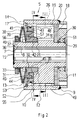
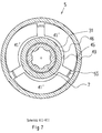
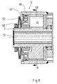
- FIGS. 2 to 4 show a first embodiment of the coupling 5 shown in the torque transmission position.
- the Coupling 5 has a coupling hub 7, which one with respect the axis of rotation 15 has central plug-in hole 8, which is determined, a non-rotatable connection between the coupling hub 7 and for example the PTO shown in FIG. 1 of the tractor.
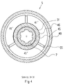
- the outer surface 9 of the clutch hub 7 is cylindrical. It is through the two side surfaces 10, 11, which run radially, limited. In the side surface 10 there is a ring recess 12. In addition are several recesses 14 distributed in the form of a slot arranged. These extend parallel to the axis of rotation 15 and are both to the outer surface 9 and to the side surfaces 10, 11 open.
- there are three circumferentially distributed recesses 14 are provided, which are uniform are distributed, i.e. an angle of 120 ° between each is included. But it can also be a different one Division should be provided such that a restart of the Coupling always takes place only after a full relative rotation of 360 °.
- the ring recess provided in the area of the side surface 10 12 forms a radially extending guide surface 13.
- Die Recesses 14 receive drivers 16 in the form of strips.
- the drivers 16 are of the same length or shorter than the recesses 14 between the two side surfaces 10, 11. They protrude however, with its end face 17 into the area of the ring recess 12 in.
- the other end face 18 of the driver 16 is supported against a sliding surface 19 of a support ring 20 Axis of rotation 15 radially adjustable from, so that the driver 16 against Tilting are guided safely.
- a first button 21 which is related to the Axis of rotation 15 runs flat. Which becomes the head of every takeaway 16 then steep, i.e. radial End face 17 serves as a second button.
- each driver 16 has a head between them the end faces 17, 18 extending torque transmission surface 22, which end in the top surfaces 23.
- the coupling is also in the direction of the arrow N opposite direction of rotation effective as an overload clutch.
- a description is only given for the direction of rotation of the drive N via the coupling hub 7.
- the support ring 20 is on one Paragraph 29 between the side surface 11 and a locking ring 30 set in the direction of the axis of rotation 15.
- a switching ring 31 is arranged on the side of the side surface 10, which is adjustable in the direction of the axis of rotation 15. This owns a bore 32 with which he with play to the outer surface 33 of a Paragraph of the coupling hub 7 is arranged. So that's the Switch ring 31 in the radial direction for a certain amount of play movable.
- the switching ring 31 has an approach that up to the ring recess 12 protrudes and the right one End face to the guide surface 13 in the torque transmission position is in plant.
- It has a first support surface 34, in the torque transfer position on the first buttons 21 of the three carriers 16 is in the system.
- the first support surface 34 can, for example, have the shape of a circumferential conical surface exhibit.
- the switching ring 31 has in addition, a second support surface 35 in the area its end face is arranged, which points to the side face 10.
- the support surface 35 is in contact with the second Button forming end face 17 of the driver 16 determines if they are in the switch-off position.
- the clutch hub 7 has at its end assigned to the switching ring 31 External thread 36 on which a nut 37 is screwed is. This serves as a support base for a spring 38, which as Belleville spring is built up and with its other end is supported against the switching ring 31 and this in the direction of the serves as a stop guiding surface 13.
- the switching ring 31 points to the side surface 10 of the coupling hub 7 arranged annular surface on an annular recess 39, which is a conical surface 40 has, which tapers towards the spring 38.
- the fly segments 41 ', the fly weight 41 form, have first guide surfaces 43 on which the axis of rotation 15 is vertical and that for guiding the centrifugal segments 41 'in the radial direction on the side surface 10 of the Serve clutch hub 7.
- the drivers can do this 16 with its end face 17 for anti-tilt guidance additionally create.
- the arrangement is such that the switching ring 31 through the Spring 38 pressed right towards the driver 16 with its first support surface 34 on the first Button 21 supports and each driver 16 in turn over its end face 18 against the sliding surface 19 of the support ring 30 is supported.
- the drivers 16 are so held that they engaged to correspondingly distributed Recesses 47, which are designed like a groove and in the bearing bore 48 a coupling sleeve 49 are arranged and with their respective torque transmission surface 22 in contact with corresponding torque transmission surfaces 50 of the Coupling sleeve 49 are.
- the coupling sleeve 49 is with its bearing bore 48 on the outer surface 9 or through the roller bearing 51 mounted on the paragraph 29 of the coupling hub 7.
- the clutch hub 7 is thereby held against axial displacement.
- Clutch hub 7 and coupling sleeve 49 can with respect to the Rotate axis of rotation 15 relative to each other or together around the Rotate axis of rotation 15 for torque transmission. As long as none Torque is applied, the switching ring 31 is also not burdened by the carriers 16.
- the Switch ring 31 has a corresponding ring surface, which as Holding surface 57 is used.
- N is in front of the recesses 47 each have a control surface 54 arranged outside of a Circle is limited by the diameter of the bearing bore 48 and is used when the set value is exceeded Torque of the driver 16 for reclosing in the direction to lead to the recesses 47.
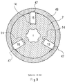
- the drivers 16 are shifted radially inwards, what is shown in Figures 5 and 6.
- the switching ring 31 moves against the force of the spring 38 to the left.
- the second buttons are created End faces 17 of the driver 16 in contact with the second Support surface 35 of the switching ring 31.
- the drivers 16 are located itself in the shutdown position in which it is approaching inwards are shifted to the axis of rotation 15. The set torque can no longer be transferred.
- the clutch hub 7 can rotate faster than the coupling sleeve 49, in the direction of drive rotation N.
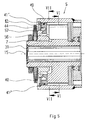
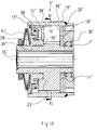
- FIGS. 10 to 13 show a further embodiment of a Coupling according to the invention, to which only the differences correspond to that according to FIGS. 2 to 9, with FIGS. 10 and 11 the torque transmission position and FIGS. 12 and 13 show the switch-off position.
- the coupling according to FIGS. 10 to 13 essentially corresponds the coupling according to Figures 2 to 9, but it is differ with regard to the training of the carriers.
- drivers 16 ' provided in the form of cylindrical rollers, the cylindrical Lateral surface each the torque transmission surface 22 ' to engage one of the recesses 47 'of the coupling sleeve 49' forms and for support on the torque transmission surface 50 'of the coupling sleeve 49' in the torque transmission position, as can be seen from FIGS. 10 and 11.
- the Carriers 16 ' have a circular end face 18', with which is supported on the sliding surface 19 'of the support ring 20' are.
- a second support surface 34 ' is provided which to rest on the second button 59 of the driver 16 'in the switch-off position. This is steeper than the first Button 21 '.
- the second button 59 arises from that the drivers 16 'are offset in diameter, a Approach 58 is formed, which ends in the end face 17 '.
- the End face 17 ' serves for additional guidance of the drivers 16' on a corresponding surface of the centrifugal weight 41 ′′.
- the drivers 16 'in the form of the cylindrical rollers are therefore double performed, and that they are at both ends their end faces 17 ', 18' guided so that tilting is effective is prevented.
- Figures 12 and 13 show the drivers 16 'in their radial shifted inwards, i.e. the axis of rotation 15 'approximate switch-off position. It can be seen that the centrifugal segments of the Centrifugal weight 41 '' are adjusted radially outwards and the Switch ring 31 'against a transfer to the torque transmission position prevent. As can be seen from Figure 13, the Driver 16 'emerged from the recesses 47' and roll on the wall of the bearing bore 48 'with relative rotation of the clutch hub 7 'to the coupling sleeve 49'.
Landscapes
- Engineering & Computer Science (AREA)
- General Engineering & Computer Science (AREA)
- Mechanical Engineering (AREA)
- Mechanical Operated Clutches (AREA)
Applications Claiming Priority (2)
| Application Number | Priority Date | Filing Date | Title |
|---|---|---|---|
| DE1997115269 DE19715269C1 (de) | 1997-04-12 | 1997-04-12 | Kupplung zur Drehmomentbegrenzung |
| DE19715269 | 1997-04-12 |
Publications (1)
| Publication Number | Publication Date |
|---|---|
| EP0870945A1 true EP0870945A1 (fr) | 1998-10-14 |
Family
ID=7826305
Family Applications (1)
| Application Number | Title | Priority Date | Filing Date |
|---|---|---|---|
| EP98105709A Ceased EP0870945A1 (fr) | 1997-04-12 | 1998-03-28 | Embrayage à limitation de couple |
Country Status (2)
| Country | Link |
|---|---|
| EP (1) | EP0870945A1 (fr) |
| DE (1) | DE19715269C1 (fr) |
Cited By (6)
| Publication number | Priority date | Publication date | Assignee | Title |
|---|---|---|---|---|
| EP1340923A1 (fr) * | 2002-02-28 | 2003-09-03 | GKN Walterscheid GmbH | Accouplement, particulièrement accouplement limitateur de couple |
| GB2403516A (en) * | 2003-07-01 | 2005-01-05 | Walterscheid Gmbh Gkn | Torque limiting coupling with predetermined re-engagement positions |
| US7037235B2 (en) | 2002-09-30 | 2006-05-02 | Jatco Ltd | Speed change ratio control unit for continuously variable transmission |
| EP2136095A1 (fr) | 2008-06-20 | 2009-12-23 | GKN Walterscheid GmbH | Couplage destiné à la limitation du couple |
| WO2014065797A1 (fr) | 2012-10-25 | 2014-05-01 | Halliburton Energy Services, Inc. | Mécanisme de transfert de couple pour outils de forage de fond de trou |
| CN114473967A (zh) * | 2022-01-21 | 2022-05-13 | 永康市皇冠电动工具制造有限公司 | 电动工具 |
Families Citing this family (2)
| Publication number | Priority date | Publication date | Assignee | Title |
|---|---|---|---|---|
| DE10141702A1 (de) | 2001-08-25 | 2003-03-06 | Deere & Co | Einrichtung zum Antrieb einer Austrageinrichtung einer landwirtschaftlichen Erntemaschine |
| DE10348068A1 (de) * | 2003-10-13 | 2005-05-25 | Gkn Walterscheid Gmbh | Kupplung zur Drehmomentbegrenzung |
Citations (6)
| Publication number | Priority date | Publication date | Assignee | Title |
|---|---|---|---|---|
| DE1216622B (de) * | 1958-12-08 | 1966-05-12 | Walterscheid Kg Jean | UEberlastkupplung mit zwei konzentrisch zueinander angeordneten zylinderfoermigen Kupplungsteilen |
| FR2429929A1 (fr) * | 1978-06-26 | 1980-01-25 | Walterscheid Gmbh Jean | Accouplement de surete pour arbres et autres organes de machines |
| DE3001566A1 (de) * | 1980-01-17 | 1981-07-23 | Daimler-Benz Ag, 7000 Stuttgart | Ueberlastkupplung zwischen einer welle und einer nabe |
| US4744447A (en) * | 1986-05-09 | 1988-05-17 | Sankyo Mfg. Co., Ltd. | Overload release clutch |
| DE4441218A1 (de) * | 1994-11-19 | 1996-05-30 | Walterscheid Gmbh Gkn | Kupplung |
| DE19538351C1 (de) * | 1995-10-14 | 1997-05-07 | Walterscheid Gmbh Gkn | Kupplung zur Drehmomentbegrenzung |
Family Cites Families (1)
| Publication number | Priority date | Publication date | Assignee | Title |
|---|---|---|---|---|
| GB849516A (en) * | 1958-02-04 | 1960-09-28 | Gelenkwellenbau Gmbh | Overload slip clutch |
-
1997
- 1997-04-12 DE DE1997115269 patent/DE19715269C1/de not_active Expired - Fee Related
-
1998
- 1998-03-28 EP EP98105709A patent/EP0870945A1/fr not_active Ceased
Patent Citations (6)
| Publication number | Priority date | Publication date | Assignee | Title |
|---|---|---|---|---|
| DE1216622B (de) * | 1958-12-08 | 1966-05-12 | Walterscheid Kg Jean | UEberlastkupplung mit zwei konzentrisch zueinander angeordneten zylinderfoermigen Kupplungsteilen |
| FR2429929A1 (fr) * | 1978-06-26 | 1980-01-25 | Walterscheid Gmbh Jean | Accouplement de surete pour arbres et autres organes de machines |
| DE3001566A1 (de) * | 1980-01-17 | 1981-07-23 | Daimler-Benz Ag, 7000 Stuttgart | Ueberlastkupplung zwischen einer welle und einer nabe |
| US4744447A (en) * | 1986-05-09 | 1988-05-17 | Sankyo Mfg. Co., Ltd. | Overload release clutch |
| DE4441218A1 (de) * | 1994-11-19 | 1996-05-30 | Walterscheid Gmbh Gkn | Kupplung |
| DE19538351C1 (de) * | 1995-10-14 | 1997-05-07 | Walterscheid Gmbh Gkn | Kupplung zur Drehmomentbegrenzung |
Cited By (13)
| Publication number | Priority date | Publication date | Assignee | Title |
|---|---|---|---|---|
| EP1340923A1 (fr) * | 2002-02-28 | 2003-09-03 | GKN Walterscheid GmbH | Accouplement, particulièrement accouplement limitateur de couple |
| US6773199B2 (en) | 2002-02-28 | 2004-08-10 | Gkn Walterscheid Gmbh | Coupling, especially torque limiting coupling |
| US7037235B2 (en) | 2002-09-30 | 2006-05-02 | Jatco Ltd | Speed change ratio control unit for continuously variable transmission |
| GB2403516A (en) * | 2003-07-01 | 2005-01-05 | Walterscheid Gmbh Gkn | Torque limiting coupling with predetermined re-engagement positions |
| GB2403516B (en) * | 2003-07-01 | 2005-06-01 | Walterscheid Gmbh Gkn | Coupling for torque limiting |
| US7993205B2 (en) | 2008-06-20 | 2011-08-09 | GKN Walterschield GmbH | Coupling for limiting the torque |
| EP2136095A1 (fr) | 2008-06-20 | 2009-12-23 | GKN Walterscheid GmbH | Couplage destiné à la limitation du couple |
| WO2014065797A1 (fr) | 2012-10-25 | 2014-05-01 | Halliburton Energy Services, Inc. | Mécanisme de transfert de couple pour outils de forage de fond de trou |
| CN104704187A (zh) * | 2012-10-25 | 2015-06-10 | 哈里伯顿能源服务公司 | 用于向下钻进的钻探工具的扭矩传递机构 |
| EP2880242A4 (fr) * | 2012-10-25 | 2016-06-15 | Halliburton Energy Services Inc | Mécanisme de transfert de couple pour outils de forage de fond de trou |
| CN104704187B (zh) * | 2012-10-25 | 2017-08-08 | 哈里伯顿能源服务公司 | 用于向下钻进的钻探工具的扭矩传递机构 |
| US10081982B2 (en) | 2012-10-25 | 2018-09-25 | Halliburton Energy Services, Inc. | Torque transfer mechanism for downhole drilling tools |
| CN114473967A (zh) * | 2022-01-21 | 2022-05-13 | 永康市皇冠电动工具制造有限公司 | 电动工具 |
Also Published As
| Publication number | Publication date |
|---|---|
| DE19715269C1 (de) | 1998-11-19 |
Similar Documents
| Publication | Publication Date | Title |
|---|---|---|
| DE2827948C3 (de) | Ausrückkupplung | |
| DE4106912C2 (de) | Kupplung mit Ein-Richtungs-Kupplungsmechanismen | |
| EP0591574B1 (fr) | Outil à main électrique motorisé | |
| EP2136095B1 (fr) | Couplage destiné à la limitation du couple | |
| AT408477B (de) | Kupplung zur drehmomentbegrenzung | |
| AT406985B (de) | Kupplung | |
| DD295700A5 (de) | Freilaufkupplung | |
| EP0756099B1 (fr) | Embrayage | |
| EP0870945A1 (fr) | Embrayage à limitation de couple | |
| EP2045480B1 (fr) | Accouplement à limitation du couple | |
| DE102009037026A1 (de) | Drehmomentbegrenzungskupplung | |
| DE1270371B (de) | Drehmoment-UEberlastsicherung an einer Gewindeschneidvorrichtung | |
| DE10201988C2 (de) | Drehmomentbegrenzungskupplung | |
| DE2828809C2 (de) | Sicherheitskupplung | |
| EP2068027B1 (fr) | Couplage de limitation du couple | |
| DE4026213C2 (fr) | ||
| DE3141353C2 (de) | Sicherheitskupplung | |
| DE102007004703B4 (de) | Sicherheitskupplung | |
| DE19734467B4 (de) | Fliehkraftgesteuerter Schaltautomat | |
| DE1164840B (de) | Fliehkraftkupplung, insbesondere fuer Kraftfahrzeuge | |
| DE102019117531B3 (de) | Aktuator für einen schaltbaren Freilauf und schaltbarer Freilauf | |
| DE102019117527B3 (de) | Automatische Zentriervorrichtung für einen schaltbaren Freilauf | |
| DE3232182A1 (de) | Freischalt-sicherheitskupplung mit selbsttaetiger wiedereinrastung | |
| DE102009015822B3 (de) | Heckenschere | |
| DE694338C (de) | Doppelseitige Freilaufkupplung |
Legal Events
| Date | Code | Title | Description |
|---|---|---|---|
| PUAI | Public reference made under article 153(3) epc to a published international application that has entered the european phase |
Free format text: ORIGINAL CODE: 0009012 |
|
| AK | Designated contracting states |
Kind code of ref document: A1 Designated state(s): AT DE FR IT NL |
|
| AX | Request for extension of the european patent |
Free format text: AL;LT;LV;MK;RO;SI |
|
| 17P | Request for examination filed |
Effective date: 19990114 |
|
| AKX | Designation fees paid |
Free format text: AT DE FR IT NL |
|
| 17Q | First examination report despatched |
Effective date: 20000811 |
|
| GRAG | Despatch of communication of intention to grant |
Free format text: ORIGINAL CODE: EPIDOS AGRA |
|
| STAA | Information on the status of an ep patent application or granted ep patent |
Free format text: STATUS: THE APPLICATION HAS BEEN REFUSED |
|
| 18R | Application refused |
Effective date: 20011125 |