EP0870879A2 - Bausatz für den Messe- und Ladenbau - Google Patents
Bausatz für den Messe- und Ladenbau Download PDFInfo
- Publication number
- EP0870879A2 EP0870879A2 EP98105525A EP98105525A EP0870879A2 EP 0870879 A2 EP0870879 A2 EP 0870879A2 EP 98105525 A EP98105525 A EP 98105525A EP 98105525 A EP98105525 A EP 98105525A EP 0870879 A2 EP0870879 A2 EP 0870879A2
- Authority
- EP
- European Patent Office
- Prior art keywords
- kit according
- profile
- profiles
- wedge
- rod
- Prior art date
- Legal status (The legal status is an assumption and is not a legal conclusion. Google has not performed a legal analysis and makes no representation as to the accuracy of the status listed.)
- Withdrawn
Links
- 238000010276 construction Methods 0.000 title description 8
- 239000004033 plastic Substances 0.000 claims description 4
- 238000003780 insertion Methods 0.000 description 1
- 230000037431 insertion Effects 0.000 description 1
- 238000004519 manufacturing process Methods 0.000 description 1
- 239000000463 material Substances 0.000 description 1
- 239000002184 metal Substances 0.000 description 1
- 238000000034 method Methods 0.000 description 1
- 239000002985 plastic film Substances 0.000 description 1
- 230000001105 regulatory effect Effects 0.000 description 1
Images


Classifications
-
- E—FIXED CONSTRUCTIONS
- E04—BUILDING
- E04B—GENERAL BUILDING CONSTRUCTIONS; WALLS, e.g. PARTITIONS; ROOFS; FLOORS; CEILINGS; INSULATION OR OTHER PROTECTION OF BUILDINGS
- E04B2/00—Walls, e.g. partitions, for buildings; Wall construction with regard to insulation; Connections specially adapted to walls
- E04B2/74—Removable non-load-bearing partitions; Partitions with a free upper edge
- E04B2/7407—Removable non-load-bearing partitions; Partitions with a free upper edge assembled using frames with infill panels or coverings only; made-up of panels and a support structure incorporating posts
- E04B2/7416—Removable non-load-bearing partitions; Partitions with a free upper edge assembled using frames with infill panels or coverings only; made-up of panels and a support structure incorporating posts with free upper edge, e.g. for use as office space dividers
- E04B2/7422—Removable non-load-bearing partitions; Partitions with a free upper edge assembled using frames with infill panels or coverings only; made-up of panels and a support structure incorporating posts with free upper edge, e.g. for use as office space dividers with separate framed panels without intermediary support posts
- E04B2/7425—Details of connection of panels
Definitions
- the invention relates to a kit for trade fair and shop construction and the same with elongated profiles with holes and connecting elements for connecting the profiles.
- kits are particularly useful for trade fair and shop construction widespread.
- the profiles can be in the desired shape be put together. You can then use it to connect cables be pulled through, the construction still just consists of the profiles through which one can easily can pass through, the cables can pass through, etc., so that in this part of the work all parts are very easily accessible are. Only when this construction is finished is z. B. with Velcro connections transparent and opaque Plastic plates or the like on the profiles attached to get the desired room layout.
- the object of the invention is to provide an improved To create a kit in which the profiles lightly together attached and detached from each other.
- each connecting element can be locked in holes using a wedge is. So it is no longer necessary to screw it all you have to do is insert or drive in a wedge, which then holds the profiles together well. To the profiles again the wedge only needs to be knocked out of each other to become.
- connecting elements which are rod-shaped or tubular Part with one arranged perpendicular to the same Disc, one at a distance from the disc and his Ends arranged, aligned with a longitudinal plane of the part Have through slot and a wedge, the thickness is substantially equal to the slot width.
- the rod-shaped or tubular part is formed by the together aligned holes of two arranged side by side Insert the profiles until the washer is inserted again prevented because it lies against the first profile.
- the Disk could e.g. B. be round, you will advantageously but make sure that the disc is rectangular
- the elongated slot is exposed on the opposite side of the pane the stick or tubular part out of the second profile.
- the slot is then in this slot Wedge inserted and pounded so that the two Profiles are clamped together because on one One side of the washer and one on the other side of the wedge Exerts pressure.
- the corresponding tensile force is from the rod or tubular part added.
- connection In contrast to the state of the art, one obtains an essential one simpler type of connection, which is also essential is faster to manufacture and solve without this type the connection has a lower reliability than previously known Types of connection.
- Disc can also be replaced by other end stops, as long as they serve the same purpose.
- the rod-shaped or tubular part is expediently hollow, So a tube or a sleeve, because it is so lighter and Material is saved.
- a washer with a guide slot for the Wedge can be used between profile and Wedge.
- This guide slot can also be a have an inclined contact surface for the wedge.
- the disc and the washer, the profile should be as large as possible cover, also extend over the entire width of the same, so that the profile is not deformed by the wedge forces becomes.
- the kit at a advantageous embodiment has connecting elements, the two articulated slotted tubes, a pull rod arranged therein and a rubber elastic Have sleeve between tie rod and tube, wherein the sleeve is compressible with the help of an external wedge is.
- corner connections in be produced in a particularly advantageous manner.
- the tubes can namely in different depths depending on the desired angle the holes are inserted without the insertion depth is set by a disc.
- the Keils and the resulting force on the tie rod the rubber-elastic sleeve is compressed and expanded the slotted tubes, which are then firmly attached to the bore wall issue.
- These tubes allow a particularly flexible Construction. When a tie rod attacks the joint, by driving in the wedge also the angle between the connected ones Profiles fixed.
- the inside diameter of the outside diameter corresponds to the tube. This can prevent that the tube expands especially where it is not in the hole, in which case the connection not be tight enough with the hole or profile could.
- fastener has an angled, in particular rod-shaped or tubular part angled by 90 ° have on the one hand near the bend with Is provided, but on the other side one Has slot for driving a wedge, so that between each disc and each wedge fixed a profile piece can be made, which also creates angle connections can be.
- Fasteners provided that consist of two right angles interconnectable elongate plates which with at least two parallel rod-shaped or tubular ones Elements are connected, one of which has a slot for has a wedge.
- the rod-shaped or tubular elements are in adjacent holes in the profile used and wedged.
- the profiles of the two plates will also be rectangular connected with each other.
- These fasteners can e.g. B. used on top of walls that are perpendicular to each other should stand. If the elongated plates are still with different Ends can be connected together, so can thereby different distances of the profiles for different Wall thicknesses can be obtained from panels that the profiles are attached.
- the profiles expediently have at least one lateral one Flange for holding the plastic plates attached to it on.
- the plastic sheets can not in this way shift their plane while moving vertically on a move especially conveniently held by Velcro will.
- the profiles are between the two flanges expediently designed to spring back to seamless To enable angular connections.
- the kit advantageously has locking balls in one Bore feet to be locked, the height of which by a Screw spindle is adjustable.
- the locking balls do not have to absorb large forces, only the feet falling out prevent down. Once the kit is set up there is then no longer any risk of the feet falling out.
- the height of the foot is adjustable by the screw spindle, the one opposite the main part of the foot or the Profile has height-adjustable footplate. To bigger ones Height differences without having to overcome long screwing, can be provided that the screw spindle is not completely is surrounded by a thread, but that the thread through a larger diameter bore running at an angle to it is cut. Then for quick height adjustment the screw spindle is folded into this larger hole, roughly shifted to the correct height and then into the thread be folded back so that the height is then finely regulated can be.
- further connecting elements such. B. to Attaching shelves and the like may be provided a plate and two round ones supported by eccentric columns Have disks whose diameter is essentially the same Corresponds to the diameter of the holes in the profile. This Slices are inserted through the holes. Subsequently the plate is moved so that it with its eccentric Columns abuts the edge of the hole. The plates can then no longer fall out.
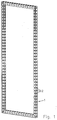
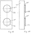
- Fig. 1 has an advantageous Embodiment of the profile frame kit with profiles 1 on, which have a rectangular cross section and pairs of Have through holes 2 arranged perpendicular to one another.
- the geometry is in the cross-sectional view 2 can be seen more clearly, in which also on a Side flanges 3 are shown, on which dashed lines hinted at the cover plates when attached after the profiles in the appropriate arrangement are set up and attached to each other.
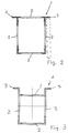
- Fig. 3 shows an embodiment of the profile 1, the between the two flanges 3 jumps back. So there is here Space for an articulated connection that allows two Profiles connected at an angle to one another without joints can be because of the space between the two flanges 3 can take up the joint.
- the connection of the profiles is done as shown in FIG. 4 to 8 can be seen in that two profiles 1 side by side to be ordered. Through aligned holes 2, a tubular part 4 is inserted until a disc 5 arranged at one end against the first Profile is present. A slot 6 protrudes on the other side beyond the second profile 1, into which a wedge 7 is inserted and fastened by hammering in. In this way the two profiles 1 are reliably held.
- the disc is round and the wedge 7 lies directly on the profile 1.
- the disc 5 is rectangular and the wedge 7 lies against a likewise rectangular washer 10, making the forces more even on the profile be distributed so that the same is not damaged.
- the profiles are of Fig. 2, in the embodiment of Figs. 6 and 7 Profiles of Fig. 3 shown. Even in the representation of Fig. 8, which shows the connection in cross section, are the profiles 3 shown.
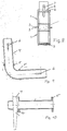
- the rod or tube is more Part 4 curved by 90 ° and has on both sides of the Curvature of a disc 5.
- Profile 1 can be attached and each with the help of a wedge pressed against the disc 5 and so attached, the in the slot 6 is inserted.
- the connecting element of FIGS. 11 to 13 has two tubular ones Parts 4, which are slotted and through a hinge 8 are hinged together.
- the tubular Elements 4 are each arranged an elastic rubber sleeve 11, the on the inside against a disc 12 and abuts on the outer side against a disc 13, which on a central tie rod 14 is slidably disposed.
- the wedge 7 which in this case is U-shaped in the axial direction and can rest against a cross pin 15, driven if the disc 13 is pressed inwards, it expands the rubber sleeve 11 so that the slotted tube 4 also expands and thereby expands in the hole to which it is pushed on, the profile is clamped.
- the right tie rod 14 acts on the joint 8, whereby it locks and a rotation of the joint is prevented.
- the inside diameter corresponds to the outside diameter of the tube, so here no expansion can take place.
- the connecting element 11 continues to the left of the joint 8 as well this is shown on the right.
- the U-shaped wedge 7 and the Cross pin 15 can also be the wedge 7 and the slot 6 of the embodiments 3-9 can be used.
- a connecting element is shown, the e.g. B. can be placed on top of profile 1, the right angle should be connected to each other.
- the fasteners have elongated rectangular plates 27 which can be connected at right angles and two have tubular projections 4, 28 with which they in the holes 2 of the profiles 1 can be used.
- a each of the tubes 4 is for connection to a wedge 7 intended.
- Holes 29 are provided, the two profiles are connected to each other at different distances, to allow different wall thicknesses for the panels, with which the profiles are clad.
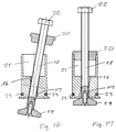
- the foot shown in FIGS. 16 and 17 has a central threaded bore 16 through which an obliquely extending bore larger diameter 17 passes.
- a screw spindle 18 with a foot 19 arranged thereon can initially, like this is shown in Fig. 16, be held obliquely so that the height can be adjusted as desired. Then she will then tilted in the axial direction (Fig. 17) when approximately the correct height is set so that the screw spindle 18th comes into engagement with the thread 16.
- the screw spindle will held in this form by an arranged on it Slidable ring 20 engages in the upper bore 21.
- the height can then be adjusted by turning a screw head 22 be finely adjusted.
- locking balls are arranged, with which the foot is held in a profile bore 2 until the weight of the profile or of the whole kit is held anyway.
- a further connecting element which has an angled plate 24 on which two columns 25 discs 26 are eccentrically attached.
- This Disks 26 have essentially the diameter of the bores 2 of the profiles and can be inserted into the holes, then, after the plate 24 has moved down, so that it rests with the columns 25 on the edge of the hole, 18 and 19 hooked and secure is held.
Landscapes
- Engineering & Computer Science (AREA)
- Architecture (AREA)
- Physics & Mathematics (AREA)
- Electromagnetism (AREA)
- Civil Engineering (AREA)
- Structural Engineering (AREA)
- Assembled Shelves (AREA)
- Mutual Connection Of Rods And Tubes (AREA)
- Joining Of Building Structures In Genera (AREA)
- Orthopedics, Nursing, And Contraception (AREA)
- Stringed Musical Instruments (AREA)
- Professional, Industrial, Or Sporting Protective Garments (AREA)
Abstract
Description
- Fig. 1
- einen Profilrahmen, bei dem die erfindungsgemäßen Verbindungselemente Verwendung finden können;
- Fig. 2
- einen Querschnitt durch ein Profilstück des Profilrahmens der Fig. 1;
- Fig. 3
- eine andere Ausführungsform des Profilstücks;
- Fig. 4 und 5
- perspektivische Ansichten der Verbindung von Profilstücken der Fig. 2 von vorne und hinten;
- Fig. 6 und 7
- perspektivische Ansichten der Verbindung von Profilstücken der Fig. 3;
- Fig. 8
- in Ansicht von oben zwei nebeneinander angeordnete Profile, die durch ein erfindungsgemäßes Verbindungselement verbunden sind;
- Fig. 9
- in Ansicht von oben eine andere Ausführungsform eines Verbindungselementes für zwei Profile;
- Fig. 10
- eine Ansicht von oben der Ausführungsform eines Verbindungselementes der Fig. 6 und 7;
- Fig. 11
- in Ansicht von der Seite eine noch andere Ausführungsform eines Verbindungselementes für zwei Profile;
- Fig. 12 und 13
- das Verbindungselement von Fig. 11 von oben in zwei verschiedenen Stellungen;
- Fig. 14 und 15
- ein weiteres Verbindungselement von oben und von der Seite; und
- Fig. 16 und 17
- die schematische Ansicht eines Fußelementes in zwei verschiedenen Stellungen;
- Fig. 18 und 19
- ein noch anderes Verbindungselement von vorne und von der Seite;
Claims (14)
- Bausatz für den Messe-, Ladenbau und dergleichen mit länglichen, mit Bohrungen (2) versehenen Profilen (1) und Verbindungselementen zum Verbinden der Profile, dadurch gekennzeichnet, daß jedes Verbindungselement unter Verwendung eines Keils (7) in Bohrungen (2) arretierbar ist.
- Bausatz nach Anspruch 1, dadurch gekennzeichnet, daß er Verbindungselemente aufweist, die einen stab- oder röhrenförmigen Teil (4) mit einer senkrecht dazu angeordneten Scheibe (5), einen in einem Abstand von der Scheibe (5) und seinen Enden angeordneten, mit einer Längsebene des Teils (4) ausgerichteten Durchgangsschlitz (6) und einen Keil (7) aufweisen, dessen Dicke im wesentlichen gleich der Schlitzbreite ist.
- Bausatz nach Anspruch 2, dadurch gekennzeichnet, daß die Scheibe (5) rechteckig ist.
- Bausatz nach Anspruch 2 oder 3, dadurch gekennzeichnet, daß zwischen Profil (1) und Keil (7) eine Unterlegscheibe (10) mit einem Führungsschlitz für den Keil (7) einsetzbar ist.
- Bausatz nach einem der Ansprüche 1 bis 4, dadurch gekennzeichnet, daß zwei stab- oder röhrenförmige Elemente (4) an ihrem mit einer Scheibe (5) versehenen Ende gelenkig (8) zu einem Verbindungselement miteinander verbunden sind.
- Bausatz nach einem der Ansprüche 1 bis 5, dadurch gekennzeichnet, daß er Verbindungselemente aufweist, die zwei gelenkig miteinander verbundene geschlitzte Röhren (4), eine jeweils darin angeordnete Zugstange und eine gummielastische Hülse (11) zwischen Zugstange (14) und Röhre (4) aufweisen, wobei die Hülse (11) mit Hilfe eines außen eingesetzten Keils (7) komprimierbar ist.
- Bausatz nach Anspruch 6, dadurch gekennzeichnet, daß auf die Röhre (4) ein Rohrstück (15) aufsetzbar ist, dessen Innendurchmesser dem Außendurchmesser der Röhre (4) entspricht.
- Bausatz nach einem der Ansprüche 1 bis 7, dadurch gekennzeichnet, daß er Verbindungselemente aufweist, die ein abgewinkeltes stab- oder röhrenförmiges Element (4) aufweisen, das auf beiden Seiten der Abwinkelung mit einer Scheibe (5) und an den Enden mit einem Schlitz (6) zum Aufnehmen eines Keils (7) versehen ist.
- Bausatz nach einem der Ansprüche 1 bis 8, dadurch gekennzeichnet, daß er Verbindungselemente aufweist, die aus zwei rechtwinklig miteinander verbindbaren länglichen Platten (27) bestehen, die mit je mindestens zwei parallelen stab- oder röhrenförmigen Elementen (4, 28) verbunden sind, von denen eines einen Schlitz (6) für einen Keil (7) aufweist.
- Bausatz nach einem der Ansprüche 1 bis 9, dadurch gekennzeichnet, daß die Profile (1) mit in gleichen Abständen angeordneten Bohrungen (2) versehen sind, wobei der Abstand des Zentrums der Bohrung (2) vom Rand des Profils (1) und der jeweils letzten Bohrung (2) vom Ende des Profils (1) gleich der Hälfte des Abstandes der Zentren von benachbarten Bohrungen (2) des Profils (1) ist.
- Bausatz nach einem der Ansprüche 1 bis 10, dadurch gekennzeichnet, daß die Profile mindestens einen seitlichen Flansch (3) zum Halten der daran zu befestigenden Kunststoffplatten aufweisen.
- Bausatz nach Anspruch 11, dadurch gekennzeichnet, daß die Profile zwischen den Flanschen (3) zurückspringend ausgebildet sind.
- Bausatz nach einem der Ansprüche 1 bis 10, dadurch gekennzeichnet, daß er mit einer Rastkugel (23) in einer Profilbohrung (2) zu verrastenden Füße aufweist, deren Höhe durch eine Schraubenspindel (18) einstellbar ist, wobei die Schraubenspindel (18) zur schnellen Höhenverstellung aus dem sie nur teilweise umgreifenden Gewinde (17) des Fußes herausklappbar ist.
- Bausatz nach einem der Ansprüche 1 bis 13, dadurch gekennzeichnet, daß er Verbindungselemente aufweist, die eine Platte (24) und zwei von exzentrischen Säulen (25) getragene runde Scheiben (26) aufweisen, deren Durchmesser im wesentlichen dem Durchmesser der Bohrungen (2) des Profils (1) entspricht.
Priority Applications (1)
| Application Number | Priority Date | Filing Date | Title |
|---|---|---|---|
| DE29823626U DE29823626U1 (de) | 1997-04-07 | 1998-03-26 | Bausatz für den Messe- und Ladenbau |
Applications Claiming Priority (2)
| Application Number | Priority Date | Filing Date | Title |
|---|---|---|---|
| DE29706156U | 1997-04-07 | ||
| DE29706156U DE29706156U1 (de) | 1997-04-07 | 1997-04-07 | Bausatz für den Messe- und Ladenbau |
Publications (2)
| Publication Number | Publication Date |
|---|---|
| EP0870879A2 true EP0870879A2 (de) | 1998-10-14 |
| EP0870879A3 EP0870879A3 (de) | 1999-05-12 |
Family
ID=8038559
Family Applications (1)
| Application Number | Title | Priority Date | Filing Date |
|---|---|---|---|
| EP98105525A Withdrawn EP0870879A3 (de) | 1997-04-07 | 1998-03-26 | Bausatz für den Messe- und Ladenbau |
Country Status (2)
| Country | Link |
|---|---|
| EP (1) | EP0870879A3 (de) |
| DE (1) | DE29706156U1 (de) |
Cited By (2)
| Publication number | Priority date | Publication date | Assignee | Title |
|---|---|---|---|---|
| EP1103729A1 (de) | 1999-11-24 | 2001-05-30 | Preuss Messebaugesellschaft mbH | Vorrichtung zum Verbinden von länglichen Profilen |
| DE102009022479A1 (de) * | 2009-02-20 | 2010-09-02 | Isinger + Merz Gmbh | Mobiles modulares Wandsystem |
Family Cites Families (4)
| Publication number | Priority date | Publication date | Assignee | Title |
|---|---|---|---|---|
| FR935686A (fr) * | 1946-10-30 | 1948-06-28 | Raccord rapide avec cone à ressort | |
| DE8419740U1 (de) * | 1984-06-30 | 1985-08-14 | Aluminium-Werke Wutöschingen GmbH, 7896 Wutöschingen | Schnellverbindung zwischen zwei aneinander anliegenden Profilstangen, beispielsweise bei Gerüsten |
| FR2714702A1 (fr) * | 1994-01-05 | 1995-07-07 | Mc Kenzie Main Stefan | Tige à coinceur. |
| DE29606690U1 (de) * | 1996-04-12 | 1996-08-01 | Girbinger, Max, 82216 Maisach | Trennwandvorrichtung für Ladenlokale |
-
1997
- 1997-04-07 DE DE29706156U patent/DE29706156U1/de not_active Expired - Lifetime
-
1998
- 1998-03-26 EP EP98105525A patent/EP0870879A3/de not_active Withdrawn
Cited By (3)
| Publication number | Priority date | Publication date | Assignee | Title |
|---|---|---|---|---|
| EP1103729A1 (de) | 1999-11-24 | 2001-05-30 | Preuss Messebaugesellschaft mbH | Vorrichtung zum Verbinden von länglichen Profilen |
| DE102009022479A1 (de) * | 2009-02-20 | 2010-09-02 | Isinger + Merz Gmbh | Mobiles modulares Wandsystem |
| DE102009022479B4 (de) | 2009-02-20 | 2022-05-19 | Isinger + Merz Gmbh | Mobiles modulares Wandsystem |
Also Published As
| Publication number | Publication date |
|---|---|
| DE29706156U1 (de) | 1998-08-06 |
| EP0870879A3 (de) | 1999-05-12 |
Similar Documents
| Publication | Publication Date | Title |
|---|---|---|
| CH617743A5 (de) | ||
| DE69521663T2 (de) | Abbaubare und veränderbare modulare Metallstruktur | |
| DE29814432U1 (de) | Trennwandanordnung | |
| EP2910699A1 (de) | Kantenprofilelementanordnung | |
| DE2325148C3 (de) | Vorrichtung zum Zusammenbau von Profilen für Metallstrukturen | |
| DE2617213A1 (de) | Tragwerk aus rohrfoermigen elementen | |
| EP0038086A2 (de) | Bausatz zur Herstellung von Gestellen, Möbeln, Regalen, transportablen Bauwerken und aus diesem Bausatz hergestellter Gegenstand | |
| EP0870879A2 (de) | Bausatz für den Messe- und Ladenbau | |
| EP0287070A1 (de) | Anordnung zurlösbaren Verbindung zweier stumpf aneinanderstossender Rohre | |
| DE3241424C2 (de) | Verbindungseinrichtung | |
| DE731774C (de) | Aus Kreuzeisen bestehendes zerlegbares Baugeruest | |
| DE102004063465A1 (de) | Mehrarmiger Rohrverbinder | |
| DE2427242A1 (de) | Verbindungselement fuer hohlprofile | |
| DE3442231A1 (de) | Raumkonstruktion | |
| EP3211138A1 (de) | Unterkonstruktion für ein bauwerk | |
| DE2812922A1 (de) | Montage-randverbindung der platten, insbesondere fuer zusammensetzbare moebel | |
| DE29603402U1 (de) | Rahmenwerk mit Winkel- oder Eckverbindungen von Metallprofilen, insbesondere aus Leichtmetall | |
| EP0528255A1 (de) | Bausatz für Skelett-Bau mit Hohlprofilen und Winkel-Verbindern | |
| DE29823626U1 (de) | Bausatz für den Messe- und Ladenbau | |
| DE102011119271B4 (de) | Verbindungssystem und Raumgitter | |
| DE2552983A1 (de) | Spannvorrichtung zum verbinden von geraetegehaeusen o.dgl. | |
| EP3816366B1 (de) | Stützkonstruktion mit mehreren länglichen profilelementen | |
| DE29719761U1 (de) | Vorrichtung zum lösbaren Verbinden von Wandelementen | |
| DE20011411U1 (de) | Verbindungselement zur Verbindung von Platten | |
| AT346023B (de) | Vierkantprofilstange sowie verbindungselement zum loesbaren verbinden solcher stangen |
Legal Events
| Date | Code | Title | Description |
|---|---|---|---|
| PUAI | Public reference made under article 153(3) epc to a published international application that has entered the european phase |
Free format text: ORIGINAL CODE: 0009012 |
|
| AK | Designated contracting states |
Kind code of ref document: A2 Designated state(s): AT BE CH DE DK ES FI FR GB GR IE IT LI LU MC NL PT SE |
|
| AX | Request for extension of the european patent |
Free format text: AL;LT;LV;MK;RO;SI |
|
| PUAL | Search report despatched |
Free format text: ORIGINAL CODE: 0009013 |
|
| AK | Designated contracting states |
Kind code of ref document: A3 Designated state(s): AT BE CH DE DK ES FI FR GB GR IE IT LI LU MC NL PT SE |
|
| AX | Request for extension of the european patent |
Free format text: AL;LT;LV;MK;RO;SI |
|
| AKX | Designation fees paid | ||
| REG | Reference to a national code |
Ref country code: DE Ref legal event code: 8566 |
|
| STAA | Information on the status of an ep patent application or granted ep patent |
Free format text: STATUS: THE APPLICATION IS DEEMED TO BE WITHDRAWN |
|
| 18D | Application deemed to be withdrawn |
Effective date: 19991113 |