EP0870879A2 - Set for the construction of exhibition stands or store furniture - Google Patents
Set for the construction of exhibition stands or store furniture Download PDFInfo
- Publication number
- EP0870879A2 EP0870879A2 EP98105525A EP98105525A EP0870879A2 EP 0870879 A2 EP0870879 A2 EP 0870879A2 EP 98105525 A EP98105525 A EP 98105525A EP 98105525 A EP98105525 A EP 98105525A EP 0870879 A2 EP0870879 A2 EP 0870879A2
- Authority
- EP
- European Patent Office
- Prior art keywords
- profile
- kit according
- wedge
- profiles
- slot
- Prior art date
- Legal status (The legal status is an assumption and is not a legal conclusion. Google has not performed a legal analysis and makes no representation as to the accuracy of the status listed.)
- Withdrawn
Links
- 238000010276 construction Methods 0.000 title description 8
- 239000004033 plastic Substances 0.000 claims description 4
- 238000003780 insertion Methods 0.000 description 1
- 230000037431 insertion Effects 0.000 description 1
- 238000004519 manufacturing process Methods 0.000 description 1
- 239000000463 material Substances 0.000 description 1
- 239000002184 metal Substances 0.000 description 1
- 238000000034 method Methods 0.000 description 1
- 239000002985 plastic film Substances 0.000 description 1
- 230000001105 regulatory effect Effects 0.000 description 1
Images


Classifications
-
- E—FIXED CONSTRUCTIONS
- E04—BUILDING
- E04B—GENERAL BUILDING CONSTRUCTIONS; WALLS, e.g. PARTITIONS; ROOFS; FLOORS; CEILINGS; INSULATION OR OTHER PROTECTION OF BUILDINGS
- E04B2/00—Walls, e.g. partitions, for buildings; Wall construction with regard to insulation; Connections specially adapted to walls
- E04B2/74—Removable non-load-bearing partitions; Partitions with a free upper edge
- E04B2/7407—Removable non-load-bearing partitions; Partitions with a free upper edge assembled using frames with infill panels or coverings only; made-up of panels and a support structure incorporating posts
- E04B2/7416—Removable non-load-bearing partitions; Partitions with a free upper edge assembled using frames with infill panels or coverings only; made-up of panels and a support structure incorporating posts with free upper edge, e.g. for use as office space dividers
- E04B2/7422—Removable non-load-bearing partitions; Partitions with a free upper edge assembled using frames with infill panels or coverings only; made-up of panels and a support structure incorporating posts with free upper edge, e.g. for use as office space dividers with separate framed panels without intermediary support posts
- E04B2/7425—Details of connection of panels
Definitions
- the invention relates to a kit for trade fair and shop construction and the same with elongated profiles with holes and connecting elements for connecting the profiles.
- kits are particularly useful for trade fair and shop construction widespread.
- the profiles can be in the desired shape be put together. You can then use it to connect cables be pulled through, the construction still just consists of the profiles through which one can easily can pass through, the cables can pass through, etc., so that in this part of the work all parts are very easily accessible are. Only when this construction is finished is z. B. with Velcro connections transparent and opaque Plastic plates or the like on the profiles attached to get the desired room layout.
- the object of the invention is to provide an improved To create a kit in which the profiles lightly together attached and detached from each other.
- each connecting element can be locked in holes using a wedge is. So it is no longer necessary to screw it all you have to do is insert or drive in a wedge, which then holds the profiles together well. To the profiles again the wedge only needs to be knocked out of each other to become.
- connecting elements which are rod-shaped or tubular Part with one arranged perpendicular to the same Disc, one at a distance from the disc and his Ends arranged, aligned with a longitudinal plane of the part Have through slot and a wedge, the thickness is substantially equal to the slot width.
- the rod-shaped or tubular part is formed by the together aligned holes of two arranged side by side Insert the profiles until the washer is inserted again prevented because it lies against the first profile.
- the Disk could e.g. B. be round, you will advantageously but make sure that the disc is rectangular
- the elongated slot is exposed on the opposite side of the pane the stick or tubular part out of the second profile.
- the slot is then in this slot Wedge inserted and pounded so that the two Profiles are clamped together because on one One side of the washer and one on the other side of the wedge Exerts pressure.
- the corresponding tensile force is from the rod or tubular part added.
- connection In contrast to the state of the art, one obtains an essential one simpler type of connection, which is also essential is faster to manufacture and solve without this type the connection has a lower reliability than previously known Types of connection.
- Disc can also be replaced by other end stops, as long as they serve the same purpose.
- the rod-shaped or tubular part is expediently hollow, So a tube or a sleeve, because it is so lighter and Material is saved.
- a washer with a guide slot for the Wedge can be used between profile and Wedge.
- This guide slot can also be a have an inclined contact surface for the wedge.
- the disc and the washer, the profile should be as large as possible cover, also extend over the entire width of the same, so that the profile is not deformed by the wedge forces becomes.
- the kit at a advantageous embodiment has connecting elements, the two articulated slotted tubes, a pull rod arranged therein and a rubber elastic Have sleeve between tie rod and tube, wherein the sleeve is compressible with the help of an external wedge is.
- corner connections in be produced in a particularly advantageous manner.
- the tubes can namely in different depths depending on the desired angle the holes are inserted without the insertion depth is set by a disc.
- the Keils and the resulting force on the tie rod the rubber-elastic sleeve is compressed and expanded the slotted tubes, which are then firmly attached to the bore wall issue.
- These tubes allow a particularly flexible Construction. When a tie rod attacks the joint, by driving in the wedge also the angle between the connected ones Profiles fixed.
- the inside diameter of the outside diameter corresponds to the tube. This can prevent that the tube expands especially where it is not in the hole, in which case the connection not be tight enough with the hole or profile could.
- fastener has an angled, in particular rod-shaped or tubular part angled by 90 ° have on the one hand near the bend with Is provided, but on the other side one Has slot for driving a wedge, so that between each disc and each wedge fixed a profile piece can be made, which also creates angle connections can be.
- Fasteners provided that consist of two right angles interconnectable elongate plates which with at least two parallel rod-shaped or tubular ones Elements are connected, one of which has a slot for has a wedge.
- the rod-shaped or tubular elements are in adjacent holes in the profile used and wedged.
- the profiles of the two plates will also be rectangular connected with each other.
- These fasteners can e.g. B. used on top of walls that are perpendicular to each other should stand. If the elongated plates are still with different Ends can be connected together, so can thereby different distances of the profiles for different Wall thicknesses can be obtained from panels that the profiles are attached.
- the profiles expediently have at least one lateral one Flange for holding the plastic plates attached to it on.
- the plastic sheets can not in this way shift their plane while moving vertically on a move especially conveniently held by Velcro will.
- the profiles are between the two flanges expediently designed to spring back to seamless To enable angular connections.
- the kit advantageously has locking balls in one Bore feet to be locked, the height of which by a Screw spindle is adjustable.
- the locking balls do not have to absorb large forces, only the feet falling out prevent down. Once the kit is set up there is then no longer any risk of the feet falling out.
- the height of the foot is adjustable by the screw spindle, the one opposite the main part of the foot or the Profile has height-adjustable footplate. To bigger ones Height differences without having to overcome long screwing, can be provided that the screw spindle is not completely is surrounded by a thread, but that the thread through a larger diameter bore running at an angle to it is cut. Then for quick height adjustment the screw spindle is folded into this larger hole, roughly shifted to the correct height and then into the thread be folded back so that the height is then finely regulated can be.
- further connecting elements such. B. to Attaching shelves and the like may be provided a plate and two round ones supported by eccentric columns Have disks whose diameter is essentially the same Corresponds to the diameter of the holes in the profile. This Slices are inserted through the holes. Subsequently the plate is moved so that it with its eccentric Columns abuts the edge of the hole. The plates can then no longer fall out.
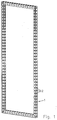
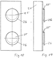
- Fig. 1 has an advantageous Embodiment of the profile frame kit with profiles 1 on, which have a rectangular cross section and pairs of Have through holes 2 arranged perpendicular to one another.
- the geometry is in the cross-sectional view 2 can be seen more clearly, in which also on a Side flanges 3 are shown, on which dashed lines hinted at the cover plates when attached after the profiles in the appropriate arrangement are set up and attached to each other.
- Fig. 3 shows an embodiment of the profile 1, the between the two flanges 3 jumps back. So there is here Space for an articulated connection that allows two Profiles connected at an angle to one another without joints can be because of the space between the two flanges 3 can take up the joint.
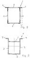
- the connection of the profiles is done as shown in FIG. 4 to 8 can be seen in that two profiles 1 side by side to be ordered. Through aligned holes 2, a tubular part 4 is inserted until a disc 5 arranged at one end against the first Profile is present. A slot 6 protrudes on the other side beyond the second profile 1, into which a wedge 7 is inserted and fastened by hammering in. In this way the two profiles 1 are reliably held.
- the disc is round and the wedge 7 lies directly on the profile 1.
- the disc 5 is rectangular and the wedge 7 lies against a likewise rectangular washer 10, making the forces more even on the profile be distributed so that the same is not damaged.
- the profiles are of Fig. 2, in the embodiment of Figs. 6 and 7 Profiles of Fig. 3 shown. Even in the representation of Fig. 8, which shows the connection in cross section, are the profiles 3 shown.
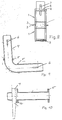
- the rod or tube is more Part 4 curved by 90 ° and has on both sides of the Curvature of a disc 5.
- Profile 1 can be attached and each with the help of a wedge pressed against the disc 5 and so attached, the in the slot 6 is inserted.
- the connecting element of FIGS. 11 to 13 has two tubular ones Parts 4, which are slotted and through a hinge 8 are hinged together.
- the tubular Elements 4 are each arranged an elastic rubber sleeve 11, the on the inside against a disc 12 and abuts on the outer side against a disc 13, which on a central tie rod 14 is slidably disposed.
- the wedge 7 which in this case is U-shaped in the axial direction and can rest against a cross pin 15, driven if the disc 13 is pressed inwards, it expands the rubber sleeve 11 so that the slotted tube 4 also expands and thereby expands in the hole to which it is pushed on, the profile is clamped.
- the right tie rod 14 acts on the joint 8, whereby it locks and a rotation of the joint is prevented.
- the inside diameter corresponds to the outside diameter of the tube, so here no expansion can take place.
- the connecting element 11 continues to the left of the joint 8 as well this is shown on the right.
- the U-shaped wedge 7 and the Cross pin 15 can also be the wedge 7 and the slot 6 of the embodiments 3-9 can be used.
- a connecting element is shown, the e.g. B. can be placed on top of profile 1, the right angle should be connected to each other.
- the fasteners have elongated rectangular plates 27 which can be connected at right angles and two have tubular projections 4, 28 with which they in the holes 2 of the profiles 1 can be used.
- a each of the tubes 4 is for connection to a wedge 7 intended.
- Holes 29 are provided, the two profiles are connected to each other at different distances, to allow different wall thicknesses for the panels, with which the profiles are clad.
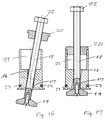
- the foot shown in FIGS. 16 and 17 has a central threaded bore 16 through which an obliquely extending bore larger diameter 17 passes.
- a screw spindle 18 with a foot 19 arranged thereon can initially, like this is shown in Fig. 16, be held obliquely so that the height can be adjusted as desired. Then she will then tilted in the axial direction (Fig. 17) when approximately the correct height is set so that the screw spindle 18th comes into engagement with the thread 16.
- the screw spindle will held in this form by an arranged on it Slidable ring 20 engages in the upper bore 21.
- the height can then be adjusted by turning a screw head 22 be finely adjusted.
- locking balls are arranged, with which the foot is held in a profile bore 2 until the weight of the profile or of the whole kit is held anyway.
- a further connecting element which has an angled plate 24 on which two columns 25 discs 26 are eccentrically attached.
- This Disks 26 have essentially the diameter of the bores 2 of the profiles and can be inserted into the holes, then, after the plate 24 has moved down, so that it rests with the columns 25 on the edge of the hole, 18 and 19 hooked and secure is held.
Abstract
Description
Die Erfindung betrifft einen Bausatz für den Messe-, Ladenbau und dergleich mit länglichen, mit Bohrungen versehenen Profilen und Verbindungselementen zum Verbinden der Profile.The invention relates to a kit for trade fair and shop construction and the same with elongated profiles with holes and connecting elements for connecting the profiles.
Solche Bausätze haben insbesondere beim Messe- und Ladenbau große Verbreitung. Die Profile können in der gewünschten Form zusammengesetzt werden. Anschließend können durch sie Kabel hindurchgezogen werden, wobei die Konstruktion immer noch lediglich aus den Profilen besteht, durch die man ohne weiteres hindurchgehen kann, die Kabel hindurchführen kann usw., so daß bei diesem Teil der Arbeiten alle Teile sehr leicht zugänglich sind. Erst wenn diese Konstruktion fertiggestellt ist, werden z. B. mit Klettverbindungen durchsichtige und undurchsichtige Kunststoffplatten oder dergleichen an den Profilen angebracht, um die gewünschte Raumaufteilung zu erhalten.Such kits are particularly useful for trade fair and shop construction widespread. The profiles can be in the desired shape be put together. You can then use it to connect cables be pulled through, the construction still just consists of the profiles through which one can easily can pass through, the cables can pass through, etc., so that in this part of the work all parts are very easily accessible are. Only when this construction is finished is z. B. with Velcro connections transparent and opaque Plastic plates or the like on the profiles attached to get the desired room layout.
Obwohl dieses Verfahren vielfältige Möglichkeiten bietet und die entsprechenden Konstruktionen für anderweitige Verwendung auch wieder abgebaut werden können, ist das Verbinden der einzelnen Profile sehr kompliziert. Diese müssen nämlich miteinander verschraubt werden, was sehr mühsam ist und häufig auch spezielle Schraubendreher erfordert. Eine andere Möglichkeit bei solchen vorbekannten Bausätzen besteht in der Verwendung von speziellen Schlössern, sogenannten Patentschlössern, die ebenfalls aufwendig und umständlich zu bedienen sind. Störend ist dabei vor allem auch der zeitliche AufWand, da Auf- und Abbau häufig an Wochenenden mit entsprechend höheren Lohnkosten durchgeführt werden müssen.Although this procedure offers many possibilities and the corresponding constructions for other use can also be dismantled, is to connect the individual profiles very complicated. They have to be together screwed, which is very tedious and often also requires special screwdrivers. Another possibility in such known kits there is Use of special locks, so-called patent locks, which are also complex and cumbersome to use are. What is particularly disturbing is the time involved, since assembly and disassembly often on weekends accordingly higher labor costs must be carried out.
Obwohl bei solchen Profilen für den Messe- und Ladenbau, die normalerweise aus Metall oder Kunststoff bestehen, wie erwähnt der einfache schnelle Aufbau und auch Abbau erforderlich ist, konnten bisher keine Lösungen gefunden werden, wie die Profile leicht verbunden und anschließend auch wieder voneinander gelöst werden können.Although with such profiles for trade fair and shop construction, the normally made of metal or plastic, as mentioned the simple quick assembly and dismantling required no solutions have yet been found, such as the profiles easily connected and then again can be separated from each other.
Die Aufgabe der Erfindung besteht darin, einen verbesserten Bausatz zu schaffen, bei dem die Profile leicht aneinander befestigt und voneinander gelöst werden können.The object of the invention is to provide an improved To create a kit in which the profiles lightly together attached and detached from each other.
Die erfindungsgemäße Lösung besteht darin, daß jedes Verbindungselement unter Verwendung eines Keils in Bohrungen arretierbar ist. Es ist also kein Verschrauben mehr notwendig, es muß lediglich ein Keil eingesetzt bzw. eingeschlagen werden, der die Profile dann gut zusammenhält. Um die Profile wieder voneinander zu lösen, braucht der Keil nur herausgeschlagen zu werden.The solution according to the invention is that each connecting element can be locked in holes using a wedge is. So it is no longer necessary to screw it all you have to do is insert or drive in a wedge, which then holds the profiles together well. To the profiles again the wedge only needs to be knocked out of each other to become.
Bei einer vorteilhaften Ausführungsform ist vorgesehen, daß er Verbindungselemente aufweist, die einen stab- oder röhrenförmiges Teil mit einer senkrecht zu demselben angeordneten Scheibe, einen in einem Abstand von der Scheibe und seinen Enden angeordneten, mit einer Längsebene des Teils ausgerichteten Durchgangsschlitz und einen Keil aufweisen, dessen Dicke im wesentlichen gleich der Schlitzbreite ist. In an advantageous embodiment it is provided that it has connecting elements which are rod-shaped or tubular Part with one arranged perpendicular to the same Disc, one at a distance from the disc and his Ends arranged, aligned with a longitudinal plane of the part Have through slot and a wedge, the thickness is substantially equal to the slot width.
Der stab- oder röhrenförmige Teil wird durch die miteinander ausgerichteten Bohrungen von zwei nebeneinander angeordneten Profilen hindurch gesteckt, bis die Scheibe ein weiteres Hineinstecken verhindert, da sie am ersten Profil anliegt. Die Scheibe könnte z. B. rund sein, vorteilhafterweise wird man aber vorsehen, daß die Scheibe rechteckig istThe rod-shaped or tubular part is formed by the together aligned holes of two arranged side by side Insert the profiles until the washer is inserted again prevented because it lies against the first profile. The Disk could e.g. B. be round, you will advantageously but make sure that the disc is rectangular
Auf der Scheibe gegenüberliegenden Seite ragt der stab- oder röhrenförmige Teil aus dem zweiten Profil heraus, wobei der längliche Schlitz freiliegt. In diesen Schlitz wird dann der Keil hineingesteckt und festgeschlagen, so daß die beiden Profile dadurch zusammengespannt werden, da auf der einen Seite die Scheibe und auf der anderen Seite der Keil eine Druckkraft ausübt. Die entsprechende Zugkraft wird vom stab- oder röhrenförmigen Teil aufgenommen. Durch einfaches Einstecken des stab- oder röhrenförmigen Teils und Einschlagen des Keils können also die zwei Profile zuverlässig und schnell miteinander verbunden werden. Diese Verbindung kann ebenso schnell wieder gelöst werden, indem der Keil aus dem Schlitz herausgeschlagen wird.On the opposite side of the pane the stick or tubular part out of the second profile, the elongated slot is exposed. The slot is then in this slot Wedge inserted and pounded so that the two Profiles are clamped together because on one One side of the washer and one on the other side of the wedge Exerts pressure. The corresponding tensile force is from the rod or tubular part added. By simply plugging it in of the rod or tubular part and hammering of the wedge can therefore reliably and the two profiles be quickly connected. This connection can can be released just as quickly by removing the wedge from the Slot is knocked out.
Im Gegensatz zum Stand der Technik erhält man also eine wesentlich einfachere Art der Verbindung, die auch wesentlich schneller herzustellen und zu lösen ist, ohne daß diese Art der Verbindung eine geringere Zuverlässigkeit hat als vorbekannte Arten der Verbindung. Selbstverständlich könnte die Scheibe auch durch andere Endanschläge ersetzt werden, solange diese den selben Zweck erfüllen. In contrast to the state of the art, one obtains an essential one simpler type of connection, which is also essential is faster to manufacture and solve without this type the connection has a lower reliability than previously known Types of connection. Of course that could Disc can also be replaced by other end stops, as long as they serve the same purpose.
Zweckmäßigerweise ist der stab- oder röhrenförmige Teil hohl, also eine Röhre oder eine Hülse, da er so leichter ist und Material eingespart wird.The rod-shaped or tubular part is expediently hollow, So a tube or a sleeve, because it is so lighter and Material is saved.
Vorteilhafterweise ist vorgesehen, daß zwischen Profil und Keil eine Unterlegscheibe mit einem Führungsschlitz für den Keil einsetzbar ist. Dieser Führungsschlitz kann auch eine schräge Anlagefläche für den Keil aufweisen. Die Scheibe und die Unterlegscheibe sollten das Profil möglichst großflächig bedecken, sich auch über die ganze Breite desselben erstrecken, damit das Profil durch die Keilkräfte nicht deformiert wird.It is advantageously provided that between profile and Wedge a washer with a guide slot for the Wedge can be used. This guide slot can also be a have an inclined contact surface for the wedge. The disc and the washer, the profile should be as large as possible cover, also extend over the entire width of the same, so that the profile is not deformed by the wedge forces becomes.
Bei einer weiteren vorteilhaften Ausführungsform sind zwei stab- oder röhrenförmige Elemente an ihren mit einer Scheibe versehenen Ende gelenkig zu einem Verbindungselement miteinander verbunden. In diesem Fall wird der Teil des stab- oder röhrenförmigen Elementes zwischen einer Scheibe und dem Schlitz für den Keil nur durch jeweils ein Profil hindurchgesteckt und daran mit Hilfe des Keils befestigt. Ggf. können zwischen Scheibe und Profil noch Unterlegscheiben vorgesehen sein, damit der Kragen und damit das Gelenk von dem Profil einen größeren Abstand hat. Das entsprechende wird mit dem gegenüberliegenden Teil zwischen der Scheibe und dem Schlitz gemacht. Infolge der gelenkigen Verbindung der beiden Teile können dann die beiden Profile in einem Winkel zueinander angeordnet werden, so daß man auch im Falle von rechteckigen Profilen, die aneinander befestigt werden, Winkel zwischen den Wandteilen erzeugen kann, die von den beiden Profilen begrenzt werden. Selbstverständlich können solche abgewinkelten Verbindungen auch zwischen Profilen hergestellt werden, die keinen rechteckigen Querschnitt haben, z. B. runden Querschnitt. Der rechteckige Querschnitt wird aber in vielen Fällen bevorzugt werden.In a further advantageous embodiment there are two rod-shaped or tubular elements on their with a disc provided end articulated to a connecting element with each other connected. In this case, the part of the stab or tubular element between a disc and the Slot for the wedge only inserted through one profile at a time and attached to it with the wedge. Possibly. can washers are also provided between the washer and the profile so that the collar and thus the joint of the profile has a larger distance. The corresponding is with the opposite part between the washer and the slot made. As a result of the articulated connection of the two parts the two profiles can then be arranged at an angle to one another be so that even in the case of rectangular Profiles that are attached to each other, angles between can produce the wall parts limited by the two profiles will. Of course, such angled ones Connections are also made between profiles that do not have a rectangular cross-section, e.g. B. round cross section. The rectangular cross-section is used in many cases to be favoured.
Weiter kann dann vorgesehen werden, daß der Bausatz bei einer vorteilhaften Ausführungsform Verbindungselemente aufweist, die zwei gelenkig miteinander verbundene geschlitzte Röhren, eine jeweils darin angeordnete Zugstange und eine gummielastische Hülse zwischen Zugstange und Röhre aufweisen, wobei die Hülse mit Hilfe eines außen eingesetzten Keils komprimierbar ist. Durch diese Elemente können Eckverbindungen in besonders vorteilhafter Weise hergestellt werden. Die Röhren können nämlich je nach gewünschtem Winkel verschieden tief in die Bohrungen eingesetzt werden, ohne das die Einsetztiefe durch eine Scheibe festgelegt wird. Durch Eintreiben des Keils und die dadurch ausgeübte Kraft auf die Zugstange wird die gummielastische Hülse zusammengedrückt und erweitert dabei die geschlitzten Röhren, die dann fest an die Bohrungswand anliegen. Diese Röhren erlauben einen besonders flexiblen Aufbau. Wenn eine Zugstange am Gelenk angreift, wird durch Eintreiben des Keils auch der Winkel zwischen den verbundenen Profilen fixiert.It can then also be provided that the kit at a advantageous embodiment has connecting elements, the two articulated slotted tubes, a pull rod arranged therein and a rubber elastic Have sleeve between tie rod and tube, wherein the sleeve is compressible with the help of an external wedge is. Through these elements corner connections in be produced in a particularly advantageous manner. The tubes can namely in different depths depending on the desired angle the holes are inserted without the insertion depth is set by a disc. By collecting the Keils and the resulting force on the tie rod the rubber-elastic sleeve is compressed and expanded the slotted tubes, which are then firmly attached to the bore wall issue. These tubes allow a particularly flexible Construction. When a tie rod attacks the joint, by driving in the wedge also the angle between the connected ones Profiles fixed.
Dabei ist vorteilhafterweise vorgesehen, daß auf die Röhre ein Rohrstück aufsetzbar ist, dessen Innendurchmesser dem Außendurchmesser der Röhre entspricht. Dadurch kann verhindert werden, daß sich die Röhre besonders dort erweitert, wo sie sich nicht in der Bohrung befindet, in welchem Fall die Verbindung mit der Bohrung bzw. dem Profil nicht fest genug sein könnte.It is advantageously provided that on the tube a piece of pipe can be placed, the inside diameter of the outside diameter corresponds to the tube. This can prevent that the tube expands especially where it is not in the hole, in which case the connection not be tight enough with the hole or profile could.
Eine noch andere vorteilhafte Art von Verbindungselementen zeichnet sich dadurch aus, daß sie einen gewinkelten, insbesondere um 90° gewinkelten stab- oder röhrenförmigen Teil aufweisen, der einerseits in der Nähe der Abwinkelung mit Scheiben versehen ist, auf der anderen Seite aber einen Schlitz zum Eintreiben eines Keils aufweist, so daß zwischen jeder Scheibe und jedem Keil jeweils ein Profilstück fixiert werden kann, wodurch ebenfalls Winkelverbindungen hergestellt werden können.Yet another advantageous type of fastener is characterized by the fact that it has an angled, in particular rod-shaped or tubular part angled by 90 ° have on the one hand near the bend with Is provided, but on the other side one Has slot for driving a wedge, so that between each disc and each wedge fixed a profile piece can be made, which also creates angle connections can be.
Soll nicht am Ende eines Profils dazu senkrecht ein zweites Profil angebracht werden, sondern irgendwo zwischen den Enden des Profils (z. B. für eine vertikale Wand, die zu einer anderen vertikalen Wand senkrecht steht) so sind zweckmäßigerweise Verbindungselemente vorgesehen, die aus zwei rechtwinklig miteinander verbindbaren länglichen Platten bestehen, die mit je mindestens zwei parallelen stab- oder röhrenförmigen Elementen verbunden sind, von denen eines einen Schlitz für einen Keil aufweist. Die stab- oder röhrigenförmigen Elemente werden dabei in nebeneinander liegende Bohrungen des Profils eingesetzt und verkeilt. Durch die rechtwinklige Verbindung der beiden Platten werden dann auch die Profile rechtwinklig miteinander verbunden. Diese Verbindungselemente können z. B. oben auf Wänden verwendet werden, die senkrecht zueinander stehen sollen. Wenn die länglichen Platten noch mit verschiedenen Enden miteinander verbunden werden können, so können dadurch unterschiedliche Abstände der Profile für unterschiedliche Wandstärken von Platten erhalten werden, die an den Profilen befestigt sind.Should not be a vertical one at the end of one profile Profile be attached, but somewhere between the ends of the profile (e.g. for a vertical wall leading to another vertical wall is perpendicular) are expedient Fasteners provided that consist of two right angles interconnectable elongate plates which with at least two parallel rod-shaped or tubular ones Elements are connected, one of which has a slot for has a wedge. The rod-shaped or tubular elements are in adjacent holes in the profile used and wedged. Through the right-angled connection The profiles of the two plates will also be rectangular connected with each other. These fasteners can e.g. B. used on top of walls that are perpendicular to each other should stand. If the elongated plates are still with different Ends can be connected together, so can thereby different distances of the profiles for different Wall thicknesses can be obtained from panels that the profiles are attached.
Mit rechteckigen Profilen läßt sich bei einer vorteilhaften Ausführungsform sehr gut eine rasterförmige Aufteilung erzielen, wenn vorgesehen wird, daß die Profile mit in gleichen Abständen angeordneten Bohrungen versehen sind, wobei der Abstand des Zentrums der Bohrung vom Rand des Profils und der Abstand der jeweils letzten Bohrung vom Ende des Profils gleich der Hälfte des Abstandes der Zentren von benachbarten Bohrungen des Profils ist.With rectangular profiles can be advantageous Embodiment very well achieve a grid-like division, if it is provided that the profiles are in the same Distances arranged holes are provided, the distance the center of the hole from the edge of the profile and the Distance of the last hole from the end of the profile equal to half the distance of the centers from neighboring ones Holes of the profile is.
An den Stellen, an denen zwei Profile zusammenstoßen (sei es am Rand oder sei es am Ende der Profilstangen) hat die jeweils außen liegende Bohrung nur den halben Abstand zum Rand bzw. Ende des Profils wie der Abstand zwischen zwei Bohrungen im Profil selbst beträgt. Da derselbe halbe Abstand auch beim jeweils anderen Profil am Rand bzw. am Ende vorgesehen ist, haben an der Stoßstelle zweier Profile zwei zwar benachbarte, aber den unterschiedlichen Profilen angehörende Bohrungen ebenfalls den gleichen Abstand wie die Bohrungen des Profils selbst, so daß mit einem anderen Profil auch solche Stoßstellen übergriffen werden können, wobei aber doch die Abstände benachbarter Bohrungen dann immer identisch sind.In the places where two profiles meet (be it on the edge or be it at the end of the profile bars) outside hole only half the distance to the edge or end of the profile like the distance between two holes in the profile itself. Since the same half distance also with the each other profile is provided at the edge or at the end, have two adjacent ones at the joint of two profiles, but holes belonging to the different profiles also the same distance as the holes in the profile itself, so that with another profile also such joints can be attacked, but the distances adjacent holes are always identical.
Die Profile weisen zweckmäßigerweise mindestens einen seitlichen Flansch zum Halten der daran befestigenden Kunststoffplatten auf. Die Kunststoffplatten können sich so nicht in ihre Ebene verschieben, während sie an einer Bewegung senkrecht dazu besonders zweckmäßig durch Klettbänder festgehalten werden. Zwischen den beiden Flanschen sind die Profile zweckmäßigerweise zurückspringend ausgebildet, um fugenlose Winkelverbindungen zu ermöglichen.The profiles expediently have at least one lateral one Flange for holding the plastic plates attached to it on. The plastic sheets can not in this way shift their plane while moving vertically on a move especially conveniently held by Velcro will. The profiles are between the two flanges expediently designed to spring back to seamless To enable angular connections.
Vorteilhafterweise weist der Bausatz mit Rastkugeln in eine Bohrung zu verrastende Füße auf, deren Höhe durch eine Schraubenspindel einstellbar ist. Die Rastkugeln müssen keine großen Kräfte aufnehmen, sondern nur das Herausfallen der Füße nach unten verhindern. Sobald der Bausatz aufgestellt ist, besteht dann nicht mehr die Gefahr, daß die Füße herausfallen. Die Höhe des Fußes ist durch die Schraubenspindel einstellbar, die eine gegenüber dem Hauptteil des Fußes bzw. dem Profil in der Höhe verstellbare Fußplatte aufweist. Um größere Höhenunterschiede ohne langes Schrauben zu überwinden, kann vorgesehen sein, daß die Schraubenspindel nicht völlig von einem Gewinde umgeben wird, sondern daß das Gewinde durch eine im Winkel dazu verlaufende Bohrung größeren Durchmessers durchschnitten wird. Zur schnellen Höhenverstellung kann dann die Schraubenspindel in diese größere Bohrung hineingeklappt, grob auf die richtige Höhe verschoben und dann in das Gewinde zurückgeklappt werden, so daß dann die Höhe fein reguliert werden kann.The kit advantageously has locking balls in one Bore feet to be locked, the height of which by a Screw spindle is adjustable. The locking balls do not have to absorb large forces, only the feet falling out prevent down. Once the kit is set up there is then no longer any risk of the feet falling out. The height of the foot is adjustable by the screw spindle, the one opposite the main part of the foot or the Profile has height-adjustable footplate. To bigger ones Height differences without having to overcome long screwing, can be provided that the screw spindle is not completely is surrounded by a thread, but that the thread through a larger diameter bore running at an angle to it is cut. Then for quick height adjustment the screw spindle is folded into this larger hole, roughly shifted to the correct height and then into the thread be folded back so that the height is then finely regulated can be.
Erfindungsgemäß können weitere Verbindungselemente z. B. zum Befestigen von Borden und dergleichen vorgesehen sein, die eine Platte und zwei von exzentrischen Säulen getragene runde Scheiben aufweisen, deren Durchmesser im wesentlichen dem Durchmesser der Bohrungen des Profils entspricht. Diese Scheiben werden durch die Bohrungen hindurchgesteckt. Anschließend wird die Platte verschoben, daß sie mit ihren exzentrischen Säulen an den Bohrungsrand stößt. Die Platten können dann nicht mehr herausfallen.According to the invention further connecting elements such. B. to Attaching shelves and the like may be provided a plate and two round ones supported by eccentric columns Have disks whose diameter is essentially the same Corresponds to the diameter of the holes in the profile. This Slices are inserted through the holes. Subsequently the plate is moved so that it with its eccentric Columns abuts the edge of the hole. The plates can then no longer fall out.
Die Erfindung wird im folgenden anhand von vorteilhaften Ausführungsformen beispielsweise beschrieben. Es zeigen:
- Fig. 1
- einen Profilrahmen, bei dem die erfindungsgemäßen Verbindungselemente Verwendung finden können;
- Fig. 2
- einen Querschnitt durch ein Profilstück des Profilrahmens der Fig. 1;
- Fig. 3
- eine andere Ausführungsform des Profilstücks;
- Fig. 4 und 5
- perspektivische Ansichten der Verbindung von Profilstücken der Fig. 2 von vorne und hinten;
- Fig. 6 und 7
- perspektivische Ansichten der Verbindung von Profilstücken der Fig. 3;
- Fig. 8
- in Ansicht von oben zwei nebeneinander angeordnete Profile, die durch ein erfindungsgemäßes Verbindungselement verbunden sind;
- Fig. 9
- in Ansicht von oben eine andere Ausführungsform eines Verbindungselementes für zwei Profile;
- Fig. 10
- eine Ansicht von oben der Ausführungsform eines
Verbindungselementes der Fig. 6
und 7; - Fig. 11
- in Ansicht von der Seite eine noch andere Ausführungsform eines Verbindungselementes für zwei Profile;
- Fig. 12
und 13 - das Verbindungselement von Fig. 11 von oben in zwei verschiedenen Stellungen;
- Fig. 14
und 15 - ein weiteres Verbindungselement von oben und von der Seite; und
- Fig. 16
und 17 - die schematische Ansicht eines Fußelementes in zwei verschiedenen Stellungen;
- Fig. 18
und 19 - ein noch anderes Verbindungselement von vorne und von der Seite;
- Fig. 1
- a profile frame in which the connecting elements according to the invention can be used;
- Fig. 2
- a cross section through a profile piece of the profile frame of Fig. 1;
- Fig. 3
- another embodiment of the profile piece;
- 4 and 5
- perspective views of the connection of profile pieces of Figure 2 from the front and rear.
- 6 and 7
- perspective views of the connection of profile pieces of Fig. 3;
- Fig. 8
- in view from above, two profiles arranged side by side, which are connected by a connecting element according to the invention;
- Fig. 9
- in top view another embodiment of a connecting element for two profiles;
- Fig. 10
- a view from above of the embodiment of a connecting element of FIGS. 6 and 7;
- Fig. 11
- in view from the side yet another embodiment of a connecting element for two profiles;
- 12 and 13
- the connecting element of Figure 11 from above in two different positions.
- 14 and 15
- another connecting element from above and from the side; and
- 16 and 17
- the schematic view of a foot element in two different positions;
- 18 and 19
- yet another connecting element from the front and from the side;
Wie dies aus Fig. 1 ersichtlich ist, weist eine vorteilhafte
Ausführungsform des Bausatzes Profilrahmen mit Profilen 1
auf, die rechteckigen Querschnitt haben und jeweils Paare von
senkrecht zueinander angeordnete Durchgangsbohrungen 2 aufweisen.
Die Geometrie ist dabei in der Querschnittsansicht
der Fig. 2 deutlicher zu sehen, in der auch noch an einer
Seite angeordnete Flansche 3 gezeigt sind, an denen gestrichelt
angedeuteten die Abdeckplatten anliegen, wenn sie angebracht
werden, nachdem die Profile in der geeigneten Anordnung
aufgestellt und aneinander befestigt sind.As can be seen from Fig. 1, has an advantageous
Embodiment of the profile frame kit with
Fig. 3 zeigt eine Ausführungsform des Profils 1, die zwischen
den beiden Flanschen 3 zurückspringt. Dadurch besteht hier
Raum für eine Gelenkverbindung, die es gestattet, daß zwei
Profile in einem Winkel zueinander fugenlos miteinander verbunden
werden können, da der Raum zwischen den beiden Flanschen
3 das Gelenk aufnehmen kann.Fig. 3 shows an embodiment of the
Die Verbindung der Profile geschieht, wie dies aus den Fig. 4
bis 8 ersichtlich ist, dadurch, daß zwei Profile 1 nebeneinander
angeordnet werden. Durch miteinander fluchtende Bohrungen
2 wird ein röhrenförmiger Teil 4 hindurchgesteckt, bis
eine an seinem einen Ende angeordnete Scheibe 5 gegen das erste
Profil anliegt. Auf der anderen Seite ragt ein Schlitz 6
über das zweite Profil 1 hinaus, in das ein Keil 7 hineingesteckt
und durch Einschlagen befestigt wird. Auf diese Weise
werden die beiden Profile 1 zuverlässig festgehalten.The connection of the profiles is done as shown in FIG. 4
to 8 can be seen in that two
Bei der Ausführungsform der Fig. 4 und 5 ist die Scheibe rund
und liegt der Keil 7 direkt am Profil 1 an. Bei der Ausführungsform
der Fig. 6 und 7 ist die Scheibe 5 rechteckig und
liegt der Keil 7 gegen eine ebenfalls rechteckige Unterlegscheibe
10 an, wodurch die Kräfte gleichmäßiger auf das Profil
verteilt werden, so daß dasselbe nicht beschädigt wird.
Bei der Ausführungsform der Fig. 4 und 5 sind dabei die Profile
von Fig. 2, bei der Ausführungsform der Fig. 6 und 7 die
Profile der Fig. 3 gezeigt. Auch bei der Darstellung der Fig.
8, die die Verbindung im Querschnitt zeigt, sind die Profile
der Fig. 3 gezeigt.In the embodiment of FIGS. 4 and 5, the disc is round
and the
Bei der Ausführungsform der Fig. 9 ist der stab- oder röhrenförmiger
Teil 4 um 90° gekrümmt und weist beiderseits der
Krümmung eine Scheibe 5 auf. Auf beide Enden kann dann ein
Profil 1 aufgesteckt werden und jeweils mit Hilfe eines Keils
gegen die Scheibe 5 gedrückt und so befestigt werden, der in
den Schlitz 6 eingeführt wird.In the embodiment of Fig. 9, the rod or tube is
In Fig. 10 ist die Ausführungsform des Verbindungselements
der Fig. 6 und 7 gezeigt, bei der der Keil 7 nicht mehr direkt
gegen das Profil anliegt, sondern gegen eine geschlitzte
Unterlegscheibe 10 drückt, so daß das Profil 1 zwischen Unterlegscheibe
10 und Scheibe 5 eingespannt wird.10 is the embodiment of the connecting
Das Verbindungselement der Fig. 11 bis 13 weist zwei röhrenförmige
Teile 4 auf, die geschlitzt sind und durch ein Gelenk
8 gelenkig miteinander verbunden sind. In den röhrenförmigen
Elementen 4 ist jeweils eine elastische Gummihülse 11 angeordnet,
die auf der inneren Seite gegen eine Scheibe 12 und
auf der äußeren Seite gegen eine Scheibe 13 anliegt, die auf
einer mittigen Zugstange 14 verschiebbar angeordnet ist. Wird
der Keil 7, der in diesem Falle in Axialrichtung U-förmig ist
und gegen einen Querstift 15 anliegen kann, eingetrieben, so
wird die Scheibe 13 nach innen gedrückt, expandiert dadurch
die Gummihülse 11, so daß sich die geschlitzte Röhre 4 ebenfalls
erweitert und sich dadurch in der Bohrung, auf die sie
aufgeschoben ist, des Profils festklemmt. Die rechte Zugstange
14 wirkt dabei auf das Gelenk 8, wodurch dieses arretiert
wird und eine Drehbewegung des Gelenks verhindert wird. Damit
eine unerwünschte Expansion in dem Bereich vermieden wird, wo
die Röhre 4 nicht von der Bohrung 2 des Profils 1 umgeben
ist, ist noch ein Rohrstück 15 aufgesetzt, dessen Innendurchmesser
dem Außendurchmesser der Röhre entspricht, so daß hier
keine Erweiterung stattfinden kann. Das Verbindungselement
der Fig. 11 setzt sich links vom Gelenk 8 genauso fort, wie
dies rechts gezeigt ist. Statt des U-förmigen Keils 7 und des
Querstifts 15 kann auch der Keil 7 und der Schlitz 6 der Ausführungsformen
der Fig. 3-9 verwendet werden.The connecting element of FIGS. 11 to 13 has two
In Fig. 15 und 16 ist ein Verbindungselement gezeigt, das
z. B. oben auf Profile 1 aufgesetzt werden kann, die rechtwinklig
miteinander verbunden werden sollen. Die Verbindungselemente
weisen längliche rechtwinklige Platten 27 auf, die
rechtwinklig miteinander verbunden werden können und zwei
röhrenförmige Vorsprünge 4, 28 aufweisen, mit denen sie in
die Bohrungen 2 der Profile 1 eingesetzt werden können. Eine
der Röhren 4 ist jeweils für die Verbindung mit einem Keil 7
vorgesehen. In dem an unterschiedlichen Abständen von den
Röhren 4, 28 an den Enden der einen länglichen Platte 27 quadratische
Löcher 29 vorgesehen sind, können die beiden Profile
mit unterschiedlichen Abständen miteinander verbunden werden,
um unterschiedliche Wandstärken für die Platten zu ermöglichen,
mit denen die Profile verkleidet werden.15 and 16, a connecting element is shown, the
e.g. B. can be placed on top of
Der in Fig. 16 und 17 gezeigte Fuß weist eine mittige Gewindebohrung
16 auf, durch die eine schräg dazu verlaufende Bohrung
größeren Durchmessers 17 hindurchgeht. Eine Schraubspindel
18 mit einem daran angeordneten Fuß 19 kann zunächst, wie
dies in Fig. 16 gezeigt ist, schräg gehalten werden, so daß
sich die Höhe beliebig verstellen läßt. Anschließend wird sie
dann in Axialrichtung gekippt (Fig. 17), wenn ungefähr die
richtige Höhe eingestellt ist, so daß die Schraubspindel 18
mit dem Gewinde 16 in Eingriff kommt. Die Schraubspindel wird
in dieser Form festgehalten, indem ein darauf angeordneter
verschiebbarer Ring 20 in der oberen Bohrung 21 einrastet.
Durch Drehen an einem Schraubenkopf 22 kann dann die Höhe
fein eingestellt werden. Bei 23 sind Rastkugeln angeordnet,
mit denen der Fuß in einer Profilbohrung 2 solange festgehalten
werden kann, bis er durch das Gewicht des Profils bzw.
des ganzen Bausatzes ohnehin festgehalten wird.The foot shown in FIGS. 16 and 17 has a central threaded bore
16 through which an obliquely extending bore
In Fig. 18 und 19 ist ein weiteres Verbindungselement gezeigt,
das eine abgewinkelte Platte 24 aufweist, an der auf
zwei Säulen 25 Scheiben 26 exentrisch angebracht sind. Diese
Scheiben 26 haben im wesentlichen den Durchmesser der Bohrungen
2 der Profile und sind in die Bohrungen hineinsteckbar,
wobei dann, nachdem sich die Platte 24 nach unten bewegt hat,
so daß sie mit den Säulen 25 auf dem Bohrungsrand anliegt,
das Befestigungselement der Fig. 18 und 19 eingehakt und sicher
festgehalten wird.18 and 19 a further connecting element is shown,
which has an angled
Claims (14)
Priority Applications (1)
| Application Number | Priority Date | Filing Date | Title |
|---|---|---|---|
| DE29823626U DE29823626U1 (en) | 1997-04-07 | 1998-03-26 | Kit for trade fair and shop construction |
Applications Claiming Priority (2)
| Application Number | Priority Date | Filing Date | Title |
|---|---|---|---|
| DE29706156U | 1997-04-07 | ||
| DE29706156U DE29706156U1 (en) | 1997-04-07 | 1997-04-07 | Kit for trade fair and shop construction |
Publications (2)
| Publication Number | Publication Date |
|---|---|
| EP0870879A2 true EP0870879A2 (en) | 1998-10-14 |
| EP0870879A3 EP0870879A3 (en) | 1999-05-12 |
Family
ID=8038559
Family Applications (1)
| Application Number | Title | Priority Date | Filing Date |
|---|---|---|---|
| EP98105525A Withdrawn EP0870879A3 (en) | 1997-04-07 | 1998-03-26 | Set for the construction of exhibition stands or store furniture |
Country Status (2)
| Country | Link |
|---|---|
| EP (1) | EP0870879A3 (en) |
| DE (1) | DE29706156U1 (en) |
Cited By (2)
| Publication number | Priority date | Publication date | Assignee | Title |
|---|---|---|---|---|
| EP1103729A1 (en) | 1999-11-24 | 2001-05-30 | Preuss Messebaugesellschaft mbH | Device for fastening elongated profiles |
| DE102009022479A1 (en) * | 2009-02-20 | 2010-09-02 | Isinger + Merz Gmbh | Mobile modular mountable and demountable wall system for construction of exhibiting- and display modules in form of stall within hall or room, has hanging fixtures for detachable fixation of lining board at supporting structure |
Citations (4)
| Publication number | Priority date | Publication date | Assignee | Title |
|---|---|---|---|---|
| FR935686A (en) * | 1946-10-30 | 1948-06-28 | Quick coupling with spring cone | |
| DE8419740U1 (en) * | 1984-06-30 | 1985-08-14 | Aluminium-Werke Wutöschingen GmbH, 7896 Wutöschingen | Quick connection between two adjacent profile bars, for example for scaffolding |
| FR2714702A1 (en) * | 1994-01-05 | 1995-07-07 | Mc Kenzie Main Stefan | Locking pin and wedge connector for locking components together used esp. in erecting tableaux in theatres etc |
| DE29606690U1 (en) * | 1996-04-12 | 1996-08-01 | Girbinger Max | Partitioning device for shops |
-
1997
- 1997-04-07 DE DE29706156U patent/DE29706156U1/en not_active Expired - Lifetime
-
1998
- 1998-03-26 EP EP98105525A patent/EP0870879A3/en not_active Withdrawn
Patent Citations (4)
| Publication number | Priority date | Publication date | Assignee | Title |
|---|---|---|---|---|
| FR935686A (en) * | 1946-10-30 | 1948-06-28 | Quick coupling with spring cone | |
| DE8419740U1 (en) * | 1984-06-30 | 1985-08-14 | Aluminium-Werke Wutöschingen GmbH, 7896 Wutöschingen | Quick connection between two adjacent profile bars, for example for scaffolding |
| FR2714702A1 (en) * | 1994-01-05 | 1995-07-07 | Mc Kenzie Main Stefan | Locking pin and wedge connector for locking components together used esp. in erecting tableaux in theatres etc |
| DE29606690U1 (en) * | 1996-04-12 | 1996-08-01 | Girbinger Max | Partitioning device for shops |
Cited By (3)
| Publication number | Priority date | Publication date | Assignee | Title |
|---|---|---|---|---|
| EP1103729A1 (en) | 1999-11-24 | 2001-05-30 | Preuss Messebaugesellschaft mbH | Device for fastening elongated profiles |
| DE102009022479A1 (en) * | 2009-02-20 | 2010-09-02 | Isinger + Merz Gmbh | Mobile modular mountable and demountable wall system for construction of exhibiting- and display modules in form of stall within hall or room, has hanging fixtures for detachable fixation of lining board at supporting structure |
| DE102009022479B4 (en) | 2009-02-20 | 2022-05-19 | Isinger + Merz Gmbh | Mobile modular wall system |
Also Published As
| Publication number | Publication date |
|---|---|
| DE29706156U1 (en) | 1998-08-06 |
| EP0870879A3 (en) | 1999-05-12 |
Similar Documents
| Publication | Publication Date | Title |
|---|---|---|
| DE1927040C3 (en) | Device for the end connection of an extruded profile to an extruded profile running through at least at the connection point, in particular made of light metal, plastic or the like | |
| DE910833C (en) | Lanyard for C-shaped profiled arms | |
| CH617743A5 (en) | ||
| EP2910699A1 (en) | Edge profile element assembly | |
| DE3603453C2 (en) | ||
| DE2750879A1 (en) | SHELVING | |
| DE2206973A1 (en) | SPATIAL ELEMENT FOR THE FORMATION OF STRUCTURES OF ALL KINDS | |
| DE2325148C3 (en) | Device for assembling profiles for metal structures | |
| DE2617213A1 (en) | STRUCTURAL STRUCTURE MADE OF TUBULAR ELEMENTS | |
| EP1524439A2 (en) | Fixing piece for grooved rear walls of cupboards | |
| DE3241424C2 (en) | Connecting device | |
| EP0870879A2 (en) | Set for the construction of exhibition stands or store furniture | |
| EP0287070A1 (en) | Arrangement for releasably connecting two tubes abutting end to end | |
| DE3442231A1 (en) | ROOM CONSTRUCTION | |
| DE731774C (en) | Scaffolding that can be dismantled from crosses | |
| DE2812922A1 (en) | Joining system for cupboard panels - uses special bolts which are locked in position by plugs with eccentric grooves | |
| DE2427242A1 (en) | Modular push fit coupling for tubular framework - angled coupling pieces having slit shanks which locate inside of tubing | |
| EP0528255A1 (en) | Framework construction set with hollow members and corner connectors | |
| EP3816366B1 (en) | Supporting structure with multiple elongate profile elements | |
| DE102011119271B4 (en) | Connection system and room grid | |
| DE202005016961U1 (en) | Kit for building frames comprises bars and connector plates which have keyhole-shaped slots, into which bolts on bars with undercut sections fit | |
| DE2940915A1 (en) | Knock-down furniture elements with simple secure joints - have threaded connectors and guide elements ensuring firm neat connections | |
| DE2552983A1 (en) | Fixing device for air conditioning cabinets etc. - has internal dowels secured by tapered transverse bolts | |
| DE2944557C2 (en) | Connection for surface construction elements or the like. | |
| AT346023B (en) | SQUARE PROFILE BAR AS WELL AS CONNECTING ELEMENT FOR RELEASING CONNECTION OF SUCH POLES |
Legal Events
| Date | Code | Title | Description |
|---|---|---|---|
| PUAI | Public reference made under article 153(3) epc to a published international application that has entered the european phase |
Free format text: ORIGINAL CODE: 0009012 |
|
| AK | Designated contracting states |
Kind code of ref document: A2 Designated state(s): AT BE CH DE DK ES FI FR GB GR IE IT LI LU MC NL PT SE |
|
| AX | Request for extension of the european patent |
Free format text: AL;LT;LV;MK;RO;SI |
|
| PUAL | Search report despatched |
Free format text: ORIGINAL CODE: 0009013 |
|
| AK | Designated contracting states |
Kind code of ref document: A3 Designated state(s): AT BE CH DE DK ES FI FR GB GR IE IT LI LU MC NL PT SE |
|
| AX | Request for extension of the european patent |
Free format text: AL;LT;LV;MK;RO;SI |
|
| AKX | Designation fees paid | ||
| REG | Reference to a national code |
Ref country code: DE Ref legal event code: 8566 |
|
| STAA | Information on the status of an ep patent application or granted ep patent |
Free format text: STATUS: THE APPLICATION IS DEEMED TO BE WITHDRAWN |
|
| 18D | Application deemed to be withdrawn |
Effective date: 19991113 |