EP0868934A1 - Système de filtration pour matières suspendues - Google Patents
Système de filtration pour matières suspendues Download PDFInfo
- Publication number
- EP0868934A1 EP0868934A1 EP97121822A EP97121822A EP0868934A1 EP 0868934 A1 EP0868934 A1 EP 0868934A1 EP 97121822 A EP97121822 A EP 97121822A EP 97121822 A EP97121822 A EP 97121822A EP 0868934 A1 EP0868934 A1 EP 0868934A1
- Authority
- EP
- European Patent Office
- Prior art keywords
- suction
- filter
- drum
- frame
- group
- Prior art date
- Legal status (The legal status is an assumption and is not a legal conclusion. Google has not performed a legal analysis and makes no representation as to the accuracy of the status listed.)
- Granted
Links
Images


Classifications
-
- B—PERFORMING OPERATIONS; TRANSPORTING
- B01—PHYSICAL OR CHEMICAL PROCESSES OR APPARATUS IN GENERAL
- B01D—SEPARATION
- B01D46/00—Filters or filtering processes specially modified for separating dispersed particles from gases or vapours
- B01D46/0002—Casings; Housings; Frame constructions
- B01D46/0013—Modules
-
- B—PERFORMING OPERATIONS; TRANSPORTING
- B01—PHYSICAL OR CHEMICAL PROCESSES OR APPARATUS IN GENERAL
- B01D—SEPARATION
- B01D46/00—Filters or filtering processes specially modified for separating dispersed particles from gases or vapours
- B01D46/24—Particle separators, e.g. dust precipitators, using rigid hollow filter bodies
-
- B—PERFORMING OPERATIONS; TRANSPORTING
- B01—PHYSICAL OR CHEMICAL PROCESSES OR APPARATUS IN GENERAL
- B01D—SEPARATION
- B01D46/00—Filters or filtering processes specially modified for separating dispersed particles from gases or vapours
- B01D46/56—Filters or filtering processes specially modified for separating dispersed particles from gases or vapours with multiple filtering elements, characterised by their mutual disposition
- B01D46/58—Filters or filtering processes specially modified for separating dispersed particles from gases or vapours with multiple filtering elements, characterised by their mutual disposition connected in parallel
-
- B—PERFORMING OPERATIONS; TRANSPORTING
- B01—PHYSICAL OR CHEMICAL PROCESSES OR APPARATUS IN GENERAL
- B01D—SEPARATION
- B01D46/00—Filters or filtering processes specially modified for separating dispersed particles from gases or vapours
- B01D46/66—Regeneration of the filtering material or filter elements inside the filter
- B01D46/68—Regeneration of the filtering material or filter elements inside the filter by means acting on the cake side involving movement with regard to the filter elements
- B01D46/682—Regeneration of the filtering material or filter elements inside the filter by means acting on the cake side involving movement with regard to the filter elements by nozzles
-
- B—PERFORMING OPERATIONS; TRANSPORTING
- B01—PHYSICAL OR CHEMICAL PROCESSES OR APPARATUS IN GENERAL
- B01D—SEPARATION
- B01D2273/00—Operation of filters specially adapted for separating dispersed particles from gases or vapours
- B01D2273/28—Making use of vacuum or underpressure
Definitions
- the present invention relates to a filter arrangement, which is a grouping of drum-like filters having air from the inside of each filter flows to the outside.
- the filter arrangement has a System for removing filter material from the inside the drum-like filter.
- HEPA waste material used in industrial plants is generated, for example in the textile industry, in wood processing or in other systems, at which considerable proportions of suspended matter or dust can be generated by different Types of filter systems are filtered out, for example, those that have large drum filters and Bag or bag filter assemblies included.
- drum filters are large cylindrical filters with automatic separation or Scraper mechanisms for removing the filter material from the drum.
- Bag filter systems are relative bulky and often require manual cleaning.
- Multiple drum filters offer a more compact one Structure that remove a large amount of suspended matter can.
- These filters have a grouping of small drum-like filters in parallel Grouping are arranged. Every single drum filter is much smaller than the conventional one Drum filter.
- a single small filter drum of a multi-drum filter arrangement about half a meter in length with a diameter of about 40 centimeters, with corresponding Dimensions for a conventional drum filter can be several feet.
- the filter arrangement leads to a relatively large total cleaning surface in compact training it is the Grouping allows a relatively large volume of air filter while requiring relatively little space.
- Each filter in the grouping is a cylinder with a filter medium around its exterior.
- Filter material can be mesh-like material trade different woven or non-woven materials or any suitable one Medium, as the expert in this field of Technology opens up. Air carrying suspended matter occurs into one end of the drum and is Circumferential filter material pulled, causing the Filter inner surfaces filter material grows up.
- the aim of the invention is to achieve the above to overcome the disadvantages explained in the art.
- a The object of the present invention is accordingly in an improved multi-drum filter arrangement create.
- Another object of the present invention is in having a multi-drum filter assembly to create an automatic cleaning system that has an improved drive system.
- Yet another object of the present invention consists of having a multi-drum filter arrangement to create a cleaning system that optimizes Has suction flow.
- each filter in the grouping has a front end into which Air carrying suspended matter flows.
- a backward one The end is opposite in the longitudinal direction to the front end.
- a filter section extends between the front end and the rear end such that the front end, the rear end and the filter section an inner region of the drum filter establish.
- a framework is in permanent operational or operational position adjacent to arranged the drum filter grouping.
- Each of Several elongated elements are operational on the frame arranged and extends into the interior of the drum filter. Any elongated element has a suction nozzle extending from it around with the inside of the cylindrical filter section the drum filter to remove Filter material to be connected from there.
- a drive mechanism is in operational Link with the elongated elements to each of these elements to rotate about its longitudinal axis and each elongated element essentially along the Moving the longitudinal axis of the drum filter back and forth, into which it extends so that a suction end the suction nozzle essentially over the inside of the filter section is moved.
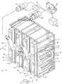
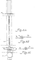
- FIG. 1 accordingly shows a current preferred embodiment of a filter system, which is generally designated by reference number 10 and a grouping 12 of drum filters 14 has.
- Each drum filter 14 has an open one Front end 16 and a closed rear end 18 on the open front end in the longitudinal direction opposite.
- the plate on rear end 18 as a flat circular disc is shown, it is understood that any suitable agent for blocking the suspended matter carrying airflow from the drum filter interior can be.
- cylindrical filter material 20 can be made of compressible or collapsible or unstable Be built up material that a ring 22nd ( Figure 2), which is attached to its front end and an elastic rope that is around rear end is attached.
- the filter material can thereby from the rear area of the grouping by compressing the clamp 22 or be loaded by going through a suitable hole a wall 24 is inserted, the bracket so is released that they are stuck in the hole with the material across the plate is pulled back, which is the rear end 18th covers, and the material is released so that the elastic rope contracts to the Hold material in place around the plate.
- the front end 16 is open to air flow. Air carrying suspended matter flows from an upstream Machine arrangement to the wall 24.
- the air flow can be upstream from wall 24 through a Pre-filters are partially filtered, like the Specialist opens up. This air is sucked through the openings in wall 24 into filters 14 and through the cylindrical material 20 of each filter pulled, causing the suspended matter on the inside 26 of the cylindrical filter material can be collected.
- a frame 28 rotatably supports several elongated Elements, such as pipes 30, which suction nozzles 32 have, which extend to the inner sides 26 out.
- Sucking or suction power or negative pressure is from a suction source 24 to each of the nozzles 32 through throttle valves 36a and 36b and through Hoses 38a and 38b applied as in Figures 1, 5 and 7 represented by flow arrows.
- Both Embodiments shown filter material flows from the inside 26 into a nozzle 32, through a pipe 30 through and into a rear chamber (which at 40 shown in dashed lines) by one of the vertical blocks 42a to 42d of the frame 28. Thereupon she is backed by a similar one Section in a horizontal block 44 to one Hose 38a or 38b to a throttle valve 36a or 36b pulled.
- the frame 28 is complete in FIG shown in the indented position in which the tubes 30 completely in the interior of their respective Drum filter 14 are introduced.
- the frame is in its fully extended or extended Position shown in Figure 2.
- Figure 2 are the nozzles 32 withdrawn to the rear panels, through which the tubes 30 are sealed with seals 52 extend.
- the tubes 30 are rotated at a speed high enough that the free ends 50 of the nozzles 32 essentially the entire surface area 26 cover when they are between their move positions shown in Figures 1 and 2.
- Vacuum or suction so that they their respective Clean inside 26 while in just move one of these directions. This will by directing the airflow from the vertical Blocks 42a and 42b to hose 38a reached by Directing the airflow from the vertical blocks 42c and 42d to hose 38b and by selective application of suction to hoses 38a and 38b.
- Suction power is accordingly by the suction source 34 the open throttle valve 36b to the suction nozzles of FIG Pipes provided on the vertical blocks 42c and 42d are arranged. Because the frame 28 in its fully extended position in Figure 2 is pulled, the nozzles clean their respective Inside pages 26. If the frame is its in Figure 2 reached position shown, the control mechanism returns 54 but the positions of the throttle valves 36a and 36b such that the remaining drum filters be cleaned when the frame is in its Position of Figure 1 returns. As in Figure 5 for example shown, a nozzle removes 32 filter material 58 from the inside 26 of a filter 14 if that Pipe 30 in the direction of the filter front end 16 emotional.
- the frame 28 is in a permanent operating position with respect to the drum filter grouping 12. That is, the frame does not move from one Grouping to another or from part of one Grouping to another during its operation.
- the frame can be removed for maintenance purposes or from a grouping or a grouping section can be removed for use in another. However, the frame does not move automatically from position to position along the group or from one grouping to another as part of it Operating.
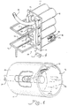
- the frame 28 with respect to the grouping 12 by one Cross spindle construction reciprocating that through a motor 60 is driven.
- motor 60 drives a transmission assembly, which is housed in a gear box 62 and in turn rotates a shaft 64 which with a cross spindle 66 through a connection 67 connected is.
- the cross spindle 66 is through a Mother added that inside the case for the drum filter is fixed.
- a Rotation of the cross spindle 66 moves the frame 28 alternately axially towards the drum filter Grouping 12 and away from it between those in Figure 1 and 2 positions shown.
- the cross spindle arrangement allows the motor 60 in to be operated in one direction.
- the pipes 30 that driven by motor 60 rotate thereby in the same direction, throughout the pre and Backward movement of the frame.
- the nozzles 32 differ from their respective Extend the tubes straight out and at the Cross spindle 66 can be a single direction spindle act such that the motor 60 its Changes direction to move the frame.
- a Reversing the motor 60 to change direction can through a variety of suitable control mechanisms caused, for example, those that limit switches, Position detectors, contact switches, sequence clocks or have computer equipment, which the direction of the motor 60 based on the Move the position of the frame 28.
- a control device 54 can be used to operate from to control both the engine and the throttle valves.
- the forward and backward movement can of the frame 28 continuously or continuously be designed so that the filter 14 is continuously cleaned will.
- the Suction nozzles 32 are used to filter material from the Pull inside 26 or separate if the Frame yourself in one direction or in both directions emotional.
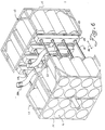
- FIG 4 Another configuration of the cross spindle assembly is shown in Figure 4, in which the frame 28th adjacent to the front ends 16 of the drum filter 14 is arranged so that the tubes 30 through the Extend front ends 16.
- the frame 28 has a moving portion 70 on a non-movable section 72 is attached by rods 74.
- the front wall 24 also as part of the frame 28 to serve.
- the cross spindle 66 can, for example, on the frame section 72, the front wall 24 or a housing the grouping 12 may be appropriate.
- the mother can received by the gear box 62 or otherwise be attached to a movable part of the frame and is rotated by the motor 60 so that the moving section 70 between one shown in Figure 4 indented position and one in FIG. 3 shown extended position moves.
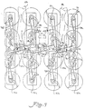
- the drive system for the pipes 30 is shown in FIG. 7 and 8 shown.
- the motor drives 60 a drive sprocket 76 through the gear box 62 on.
- the drive sprocket 76 is the drive sprocket 76 by a double sprocket, which has driven sprockets 77a and 77b, which drive belts or chains 78b and 78c.
- Tensioned by a series of idlers belts 78b and 78c drive sprockets 80 which in turn drive the tubes 30 ( Figure 1) to the To set nozzles 32 in rotation.
- Figure 7 shows a grouping of filters with four vertical columns.
- the system can be used to be any number of lines or To drive columns.
- the strap or chain 78b for a two-by-four grouping, as shown in Figure 4 to the opposite Side of the pulley 82 down to the pulley 84 are run.
- a similar arrangement would between the pulleys 86 and 88 with regard to the belt 78c.
- one of the hoses 38a and 38b (or both if a dual or double system is used, as explained above) on others Be placed on the frame 28 for example on a vertical element 42, such as shown in Figure 4.
- the connection connects the vertical Elements mechanically through the horizontal Element and allows air flow in between, for example through front channels 40 as in Figure 1 shown. Multiple columns can be added to the frame to groupings of different sizes to provide.
- the vertical elements can through a similar connection mechanism vertically be extended to provide additional rows. This construction represents a flexible cleaning system ready by a single motor can be driven.
- the tubes of the four-by-four grouping driven by four belts driven by four belts.
- the operation of belts 78b and 78c is above explained.
- the one with the vertical elements 42a and 42d are rotatably connected pipes, however driven by belts or chains 78a and 78d.
- the belt 78a is through a double sprocket 90 driven as shown in Figure 8B while the belt 78d is driven by a double sprocket 92 becomes as shown in Fig. 8C.
- An additional one vertical section can go to the vertical section 42a can be added, for example by the connection explained above and by returning of the belt 78a to the other side of the Tensioner pulley 94, around a double sprocket of a subsequent element.
- the belt and pulley assembly shown in Figure 7 is on the frame between the vertical ones Elements and the filter grouping.
- the Arrangement is different from the other figures for the sake of Clarity omitted. It is noted that more suitable drive arrangements can be used.
- FIG 6 Another preferred embodiment is shown in FIG 6, in which a single frame 28 two Groupings of tubes 30 carries in opposite directions Extend directions to back to back to provide lying filter groups 12.
- the frame 28 reciprocates as if through the Arrow 46 shown to filter both groups in the way explained above to clean.
- All of the tubes 30 are connected by a common belt and driven pulley system, such as shown in Figure 7, in which each Pair of opposing tubes 30 through a common one Sprocket 80 is driven ( Figure 7).
- There the belt and pulley system one side of the frame 28 can be arranged a set of tubes 30 extends through the vertical Elements for their respective drive sprockets 80. Accordingly, 32 tubes 30 from FIG. 6 can be driven by a single motor 60.
Landscapes
- Chemical & Material Sciences (AREA)
- Chemical Kinetics & Catalysis (AREA)
- Preliminary Treatment Of Fibers (AREA)
- Filtering Of Dispersed Particles In Gases (AREA)
Applications Claiming Priority (2)
| Application Number | Priority Date | Filing Date | Title |
|---|---|---|---|
| US823807 | 1997-03-24 | ||
| US08/823,807 US5814114A (en) | 1997-03-24 | 1997-03-24 | Airborne waste filter arrangement |
Publications (2)
| Publication Number | Publication Date |
|---|---|
| EP0868934A1 true EP0868934A1 (fr) | 1998-10-07 |
| EP0868934B1 EP0868934B1 (fr) | 2004-06-16 |
Family
ID=25239784
Family Applications (1)
| Application Number | Title | Priority Date | Filing Date |
|---|---|---|---|
| EP97121822A Expired - Lifetime EP0868934B1 (fr) | 1997-03-24 | 1997-12-11 | Système de filtration pour matières suspendues |
Country Status (5)
| Country | Link |
|---|---|
| US (1) | US5814114A (fr) |
| EP (1) | EP0868934B1 (fr) |
| BR (1) | BR9704798A (fr) |
| DE (1) | DE59711722D1 (fr) |
| ES (1) | ES2221945T3 (fr) |
Cited By (3)
| Publication number | Priority date | Publication date | Assignee | Title |
|---|---|---|---|---|
| DE202012002008U1 (de) | 2012-02-25 | 2012-04-04 | Ltg Aktiengesellschaft | Luftfiltersystem |
| DE102012003824A1 (de) | 2012-02-25 | 2013-08-29 | Ltg Aktiengesellschaft | Luftfiltersystem |
| CN104475399A (zh) * | 2014-12-19 | 2015-04-01 | 江苏精亚环境科技有限公司 | 一种活动吸箱 |
Families Citing this family (10)
| Publication number | Priority date | Publication date | Assignee | Title |
|---|---|---|---|---|
| US6890365B2 (en) * | 2003-05-09 | 2005-05-10 | Dillman Equipment, Inc. | Reverse-flow baghouse |
| US7318249B2 (en) * | 2004-02-23 | 2008-01-15 | Kun Yi Lin | Vacuum collector having sweeping device |
| US7309366B2 (en) * | 2005-04-05 | 2007-12-18 | Jensen Robert M | Bag cleaning compressed air nozzle |
| DE102006000310A1 (de) * | 2006-06-26 | 2008-01-10 | Hilti Ag | Staubsaugvorrichtung |
| US20090151306A1 (en) * | 2007-12-13 | 2009-06-18 | Chang Tjer Industrial Co., Ltd. | Dust removing device for dust collector |
| US8961448B2 (en) * | 2008-01-28 | 2015-02-24 | Peter Forsell | Implantable drainage device |
| CN107321088B (zh) * | 2017-08-22 | 2018-07-03 | 新乡市新垣防腐保温制品有限公司 | 一种高效粉尘处理器 |
| GB2584410B (en) * | 2019-05-16 | 2022-12-07 | Dyson Technology Ltd | A filter assembly |
| KR102183820B1 (ko) * | 2020-03-10 | 2020-11-30 | 주식회사 그레넥스 | 섬유상 여과기의 역세정 흡입장치 |
| US20230405508A1 (en) * | 2022-06-20 | 2023-12-21 | William L McLean, Jr. | Air filter cleaning device |
Citations (4)
| Publication number | Priority date | Publication date | Assignee | Title |
|---|---|---|---|---|
| US4154588A (en) * | 1977-09-27 | 1979-05-15 | Herndon Marion E Jr | Cylindrical cell self-cleaning filter |
| US4289510A (en) * | 1980-01-21 | 1981-09-15 | Conor Corporation | Internal loading cylindrical filter with unsupported tubular filter fabric |
| EP0459307A2 (fr) * | 1990-05-29 | 1991-12-04 | Ltg Lufttechnische Gmbh | Dispositif filtrant comportant plusieurs éléments filtrants tubulaires |
| US5571299A (en) * | 1995-04-28 | 1996-11-05 | Tonn; Harold H. | Dust collector |
Family Cites Families (8)
| Publication number | Priority date | Publication date | Assignee | Title |
|---|---|---|---|---|
| DE604096C (de) * | 1933-08-30 | 1934-10-15 | Heinrich Luehr | Schlauchfilter |
| GB1077718A (en) * | 1963-05-29 | 1967-08-02 | Leesona Holt Ltd | Improvements in suction cleaning equipment for winding machines |
| US3606735A (en) * | 1969-07-01 | 1971-09-21 | Aeronca Inc | Air filter assembly providing increased filtering surface area for a given volumetric size |
| US4251237A (en) * | 1980-02-13 | 1981-02-17 | Smith Randall E | Air filter and method of filtering |
| JPS57153775A (en) * | 1981-03-16 | 1982-09-22 | Kikkoman Shoyu Co Ltd | Classifier |
| US4364755A (en) * | 1981-12-17 | 1982-12-21 | Hans Ferri | Filter assembly |
| US5453117A (en) * | 1994-03-22 | 1995-09-26 | Luwa Ag | Fluid filter and method of separating entrained particulate matter from a moving fluid stream |
| US5507851A (en) * | 1994-07-15 | 1996-04-16 | Kennington; H. L. | Filter cleaning apparatus |
-
1997
- 1997-03-24 US US08/823,807 patent/US5814114A/en not_active Expired - Lifetime
- 1997-09-23 BR BR9704798A patent/BR9704798A/pt not_active IP Right Cessation
- 1997-12-11 ES ES97121822T patent/ES2221945T3/es not_active Expired - Lifetime
- 1997-12-11 EP EP97121822A patent/EP0868934B1/fr not_active Expired - Lifetime
- 1997-12-11 DE DE59711722T patent/DE59711722D1/de not_active Expired - Lifetime
Patent Citations (5)
| Publication number | Priority date | Publication date | Assignee | Title |
|---|---|---|---|---|
| US4154588A (en) * | 1977-09-27 | 1979-05-15 | Herndon Marion E Jr | Cylindrical cell self-cleaning filter |
| US4289510A (en) * | 1980-01-21 | 1981-09-15 | Conor Corporation | Internal loading cylindrical filter with unsupported tubular filter fabric |
| EP0459307A2 (fr) * | 1990-05-29 | 1991-12-04 | Ltg Lufttechnische Gmbh | Dispositif filtrant comportant plusieurs éléments filtrants tubulaires |
| US5114444A (en) * | 1990-05-29 | 1992-05-19 | Ltg Lufttechnische Gmbh | Filter arrangement including at least one drum-type filter |
| US5571299A (en) * | 1995-04-28 | 1996-11-05 | Tonn; Harold H. | Dust collector |
Cited By (4)
| Publication number | Priority date | Publication date | Assignee | Title |
|---|---|---|---|---|
| DE202012002008U1 (de) | 2012-02-25 | 2012-04-04 | Ltg Aktiengesellschaft | Luftfiltersystem |
| DE102012003824A1 (de) | 2012-02-25 | 2013-08-29 | Ltg Aktiengesellschaft | Luftfiltersystem |
| CN104475399A (zh) * | 2014-12-19 | 2015-04-01 | 江苏精亚环境科技有限公司 | 一种活动吸箱 |
| CN104475399B (zh) * | 2014-12-19 | 2017-01-11 | 江苏精亚环境科技有限公司 | 一种活动吸箱 |
Also Published As
| Publication number | Publication date |
|---|---|
| EP0868934B1 (fr) | 2004-06-16 |
| US5814114A (en) | 1998-09-29 |
| ES2221945T3 (es) | 2005-01-16 |
| DE59711722D1 (de) | 2004-07-22 |
| BR9704798A (pt) | 1998-12-01 |
Similar Documents
| Publication | Publication Date | Title |
|---|---|---|
| DE8503261U1 (de) | Selbstreinigende Filtereinrichtung | |
| DE2917986C2 (de) | Stehende Filtriervorrichtung | |
| DE4017206C2 (de) | Filteranordnung mit mehreren Trommelfiltern | |
| EP0868934B1 (fr) | Système de filtration pour matières suspendues | |
| EP2283908A1 (fr) | Dispositif destiné à la préparation de lubrifiant réfrigérant | |
| DE1930117B2 (de) | Filterapparat fuer fluessigkeit | |
| DE2226687A1 (de) | Verfahren zum Filtern eines schlammigen Gutes und Vorrichtung zur Durchführung des Verfahrens | |
| CH652045A5 (de) | Vorrichtung zum abtrennen von mitgerissenem teilchenfoermigem material aus einem fluid. | |
| DE1935153C3 (de) | Filter mit einem Filterschirm | |
| DE69028135T2 (de) | Vorrichtung zum Reinigen einer Spinnereimaschine | |
| CH673591A5 (fr) | ||
| DE102006036480A1 (de) | Luftfiltersystem sowie Verfahren zum Reinigen von Luft | |
| DE2130326C3 (de) | Filterpresse | |
| DE69604573T2 (de) | Selbstreinigendes filter für pneumatische kreislaufe | |
| EP0673665B1 (fr) | Filtre pour un fluide et procédé pour éliminer des poussières d'un courant de fluide | |
| EP0565857A1 (fr) | Filtre à pression de liquides | |
| DE3939645C3 (de) | Staubabscheider mit schlauchförmigen Filterelementen und Verfahren zum Wechseln derselben | |
| EP0391091B1 (fr) | Filtre à bande avec aspiration | |
| DE3910930C2 (fr) | ||
| DE19837775C2 (de) | Filtervorrichtung | |
| DE2639493C2 (de) | Unterdruck-Trommelfilter mit automatisch gesteuertem Transport von einem oder mehreren Bändern im Gleichklang mit der Filtertrommelbewegung zum Ausfiltern von Feststoffen aus Flüssigkeiten | |
| DE1407956A1 (de) | Trockenfilter-Reinigungssystem | |
| DE162091C (fr) | ||
| CH639003A5 (de) | Pressfiltervorrichtung. | |
| DE877856C (de) | Vorrichtung zur Abscheidung von Staub aus Luft oder anderen Gasen |
Legal Events
| Date | Code | Title | Description |
|---|---|---|---|
| PUAI | Public reference made under article 153(3) epc to a published international application that has entered the european phase |
Free format text: ORIGINAL CODE: 0009012 |
|
| AK | Designated contracting states |
Kind code of ref document: A1 Designated state(s): CH DE ES FR GB IT LI |
|
| 17P | Request for examination filed |
Effective date: 19990407 |
|
| AKX | Designation fees paid |
Free format text: CH DE ES FR GB IT LI |
|
| 17Q | First examination report despatched |
Effective date: 20020924 |
|
| GRAP | Despatch of communication of intention to grant a patent |
Free format text: ORIGINAL CODE: EPIDOSNIGR1 |
|
| GRAS | Grant fee paid |
Free format text: ORIGINAL CODE: EPIDOSNIGR3 |
|
| GRAA | (expected) grant |
Free format text: ORIGINAL CODE: 0009210 |
|
| AK | Designated contracting states |
Kind code of ref document: B1 Designated state(s): CH DE ES FR GB IT LI |
|
| REG | Reference to a national code |
Ref country code: GB Ref legal event code: FG4D Free format text: NOT ENGLISH |
|
| REG | Reference to a national code |
Ref country code: CH Ref legal event code: EP |
|
| REF | Corresponds to: |
Ref document number: 59711722 Country of ref document: DE Date of ref document: 20040722 Kind code of ref document: P |
|
| REG | Reference to a national code |
Ref country code: CH Ref legal event code: NV Representative=s name: TROESCH SCHEIDEGGER WERNER AG |
|
| GBT | Gb: translation of ep patent filed (gb section 77(6)(a)/1977) |
Effective date: 20040823 |
|
| REG | Reference to a national code |
Ref country code: ES Ref legal event code: FG2A Ref document number: 2221945 Country of ref document: ES Kind code of ref document: T3 |
|
| ET | Fr: translation filed | ||
| PLBE | No opposition filed within time limit |
Free format text: ORIGINAL CODE: 0009261 |
|
| STAA | Information on the status of an ep patent application or granted ep patent |
Free format text: STATUS: NO OPPOSITION FILED WITHIN TIME LIMIT |
|
| 26N | No opposition filed |
Effective date: 20050317 |
|
| REG | Reference to a national code |
Ref country code: CH Ref legal event code: PUE Owner name: LTG AEROB AIR ENGINEERING GMBH Free format text: LTG LUFTTECHNISCHE GMBH#WERNERSTRASSE 119-129#70435 STUTTGART (DE) -TRANSFER TO- LTG AEROB AIR ENGINEERING GMBH#HAERTLESAECKERSTRASSE 5#71336 WAIBLINGEN (DE) |
|
| REG | Reference to a national code |
Ref country code: GB Ref legal event code: 732E |
|
| REG | Reference to a national code |
Ref country code: FR Ref legal event code: TP |
|
| REG | Reference to a national code |
Ref country code: ES Ref legal event code: PC2A |
|
| PGFP | Annual fee paid to national office [announced via postgrant information from national office to epo] |
Ref country code: ES Payment date: 20091222 Year of fee payment: 13 Ref country code: CH Payment date: 20091224 Year of fee payment: 13 |
|
| PGFP | Annual fee paid to national office [announced via postgrant information from national office to epo] |
Ref country code: IT Payment date: 20091223 Year of fee payment: 13 Ref country code: GB Payment date: 20091218 Year of fee payment: 13 Ref country code: FR Payment date: 20100108 Year of fee payment: 13 |
|
| PGFP | Annual fee paid to national office [announced via postgrant information from national office to epo] |
Ref country code: DE Payment date: 20100123 Year of fee payment: 13 |
|
| REG | Reference to a national code |
Ref country code: CH Ref legal event code: PL |
|
| GBPC | Gb: european patent ceased through non-payment of renewal fee |
Effective date: 20101211 |
|
| REG | Reference to a national code |
Ref country code: FR Ref legal event code: ST Effective date: 20110831 |
|
| PG25 | Lapsed in a contracting state [announced via postgrant information from national office to epo] |
Ref country code: CH Free format text: LAPSE BECAUSE OF NON-PAYMENT OF DUE FEES Effective date: 20101231 Ref country code: LI Free format text: LAPSE BECAUSE OF NON-PAYMENT OF DUE FEES Effective date: 20101231 Ref country code: FR Free format text: LAPSE BECAUSE OF NON-PAYMENT OF DUE FEES Effective date: 20110103 |
|
| REG | Reference to a national code |
Ref country code: DE Ref legal event code: R119 Ref document number: 59711722 Country of ref document: DE Effective date: 20110701 |
|
| PG25 | Lapsed in a contracting state [announced via postgrant information from national office to epo] |
Ref country code: DE Free format text: LAPSE BECAUSE OF NON-PAYMENT OF DUE FEES Effective date: 20110701 Ref country code: GB Free format text: LAPSE BECAUSE OF NON-PAYMENT OF DUE FEES Effective date: 20101211 |
|
| PG25 | Lapsed in a contracting state [announced via postgrant information from national office to epo] |
Ref country code: IT Free format text: LAPSE BECAUSE OF NON-PAYMENT OF DUE FEES Effective date: 20101211 |
|
| REG | Reference to a national code |
Ref country code: ES Ref legal event code: FD2A Effective date: 20120220 |
|
| PG25 | Lapsed in a contracting state [announced via postgrant information from national office to epo] |
Ref country code: ES Free format text: LAPSE BECAUSE OF NON-PAYMENT OF DUE FEES Effective date: 20101212 |