EP0868934A1 - Filter system for airborne particles - Google Patents
Filter system for airborne particles Download PDFInfo
- Publication number
- EP0868934A1 EP0868934A1 EP97121822A EP97121822A EP0868934A1 EP 0868934 A1 EP0868934 A1 EP 0868934A1 EP 97121822 A EP97121822 A EP 97121822A EP 97121822 A EP97121822 A EP 97121822A EP 0868934 A1 EP0868934 A1 EP 0868934A1
- Authority
- EP
- European Patent Office
- Prior art keywords
- suction
- filter
- drum
- frame
- group
- Prior art date
- Legal status (The legal status is an assumption and is not a legal conclusion. Google has not performed a legal analysis and makes no representation as to the accuracy of the status listed.)
- Granted
Links
Images


Classifications
-
- B—PERFORMING OPERATIONS; TRANSPORTING
- B01—PHYSICAL OR CHEMICAL PROCESSES OR APPARATUS IN GENERAL
- B01D—SEPARATION
- B01D46/00—Filters or filtering processes specially modified for separating dispersed particles from gases or vapours
- B01D46/0002—Casings; Housings; Frame constructions
- B01D46/0013—Modules
-
- B—PERFORMING OPERATIONS; TRANSPORTING
- B01—PHYSICAL OR CHEMICAL PROCESSES OR APPARATUS IN GENERAL
- B01D—SEPARATION
- B01D46/00—Filters or filtering processes specially modified for separating dispersed particles from gases or vapours
- B01D46/24—Particle separators, e.g. dust precipitators, using rigid hollow filter bodies
-
- B—PERFORMING OPERATIONS; TRANSPORTING
- B01—PHYSICAL OR CHEMICAL PROCESSES OR APPARATUS IN GENERAL
- B01D—SEPARATION
- B01D46/00—Filters or filtering processes specially modified for separating dispersed particles from gases or vapours
- B01D46/56—Filters or filtering processes specially modified for separating dispersed particles from gases or vapours with multiple filtering elements, characterised by their mutual disposition
- B01D46/58—Filters or filtering processes specially modified for separating dispersed particles from gases or vapours with multiple filtering elements, characterised by their mutual disposition connected in parallel
-
- B—PERFORMING OPERATIONS; TRANSPORTING
- B01—PHYSICAL OR CHEMICAL PROCESSES OR APPARATUS IN GENERAL
- B01D—SEPARATION
- B01D46/00—Filters or filtering processes specially modified for separating dispersed particles from gases or vapours
- B01D46/66—Regeneration of the filtering material or filter elements inside the filter
- B01D46/68—Regeneration of the filtering material or filter elements inside the filter by means acting on the cake side involving movement with regard to the filter elements
- B01D46/682—Regeneration of the filtering material or filter elements inside the filter by means acting on the cake side involving movement with regard to the filter elements by nozzles
-
- B—PERFORMING OPERATIONS; TRANSPORTING
- B01—PHYSICAL OR CHEMICAL PROCESSES OR APPARATUS IN GENERAL
- B01D—SEPARATION
- B01D2273/00—Operation of filters specially adapted for separating dispersed particles from gases or vapours
- B01D2273/28—Making use of vacuum or underpressure
Definitions
- the present invention relates to a filter arrangement, which is a grouping of drum-like filters having air from the inside of each filter flows to the outside.
- the filter arrangement has a System for removing filter material from the inside the drum-like filter.
- HEPA waste material used in industrial plants is generated, for example in the textile industry, in wood processing or in other systems, at which considerable proportions of suspended matter or dust can be generated by different Types of filter systems are filtered out, for example, those that have large drum filters and Bag or bag filter assemblies included.
- drum filters are large cylindrical filters with automatic separation or Scraper mechanisms for removing the filter material from the drum.
- Bag filter systems are relative bulky and often require manual cleaning.
- Multiple drum filters offer a more compact one Structure that remove a large amount of suspended matter can.
- These filters have a grouping of small drum-like filters in parallel Grouping are arranged. Every single drum filter is much smaller than the conventional one Drum filter.
- a single small filter drum of a multi-drum filter arrangement about half a meter in length with a diameter of about 40 centimeters, with corresponding Dimensions for a conventional drum filter can be several feet.
- the filter arrangement leads to a relatively large total cleaning surface in compact training it is the Grouping allows a relatively large volume of air filter while requiring relatively little space.
- Each filter in the grouping is a cylinder with a filter medium around its exterior.
- Filter material can be mesh-like material trade different woven or non-woven materials or any suitable one Medium, as the expert in this field of Technology opens up. Air carrying suspended matter occurs into one end of the drum and is Circumferential filter material pulled, causing the Filter inner surfaces filter material grows up.
- the aim of the invention is to achieve the above to overcome the disadvantages explained in the art.
- a The object of the present invention is accordingly in an improved multi-drum filter arrangement create.
- Another object of the present invention is in having a multi-drum filter assembly to create an automatic cleaning system that has an improved drive system.
- Yet another object of the present invention consists of having a multi-drum filter arrangement to create a cleaning system that optimizes Has suction flow.
- each filter in the grouping has a front end into which Air carrying suspended matter flows.
- a backward one The end is opposite in the longitudinal direction to the front end.
- a filter section extends between the front end and the rear end such that the front end, the rear end and the filter section an inner region of the drum filter establish.
- a framework is in permanent operational or operational position adjacent to arranged the drum filter grouping.
- Each of Several elongated elements are operational on the frame arranged and extends into the interior of the drum filter. Any elongated element has a suction nozzle extending from it around with the inside of the cylindrical filter section the drum filter to remove Filter material to be connected from there.
- a drive mechanism is in operational Link with the elongated elements to each of these elements to rotate about its longitudinal axis and each elongated element essentially along the Moving the longitudinal axis of the drum filter back and forth, into which it extends so that a suction end the suction nozzle essentially over the inside of the filter section is moved.
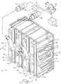
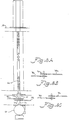
- FIG. 1 accordingly shows a current preferred embodiment of a filter system, which is generally designated by reference number 10 and a grouping 12 of drum filters 14 has.
- Each drum filter 14 has an open one Front end 16 and a closed rear end 18 on the open front end in the longitudinal direction opposite.
- the plate on rear end 18 as a flat circular disc is shown, it is understood that any suitable agent for blocking the suspended matter carrying airflow from the drum filter interior can be.
- cylindrical filter material 20 can be made of compressible or collapsible or unstable Be built up material that a ring 22nd ( Figure 2), which is attached to its front end and an elastic rope that is around rear end is attached.
- the filter material can thereby from the rear area of the grouping by compressing the clamp 22 or be loaded by going through a suitable hole a wall 24 is inserted, the bracket so is released that they are stuck in the hole with the material across the plate is pulled back, which is the rear end 18th covers, and the material is released so that the elastic rope contracts to the Hold material in place around the plate.
- the front end 16 is open to air flow. Air carrying suspended matter flows from an upstream Machine arrangement to the wall 24.
- the air flow can be upstream from wall 24 through a Pre-filters are partially filtered, like the Specialist opens up. This air is sucked through the openings in wall 24 into filters 14 and through the cylindrical material 20 of each filter pulled, causing the suspended matter on the inside 26 of the cylindrical filter material can be collected.
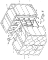
- a frame 28 rotatably supports several elongated Elements, such as pipes 30, which suction nozzles 32 have, which extend to the inner sides 26 out.
- Sucking or suction power or negative pressure is from a suction source 24 to each of the nozzles 32 through throttle valves 36a and 36b and through Hoses 38a and 38b applied as in Figures 1, 5 and 7 represented by flow arrows.
- Both Embodiments shown filter material flows from the inside 26 into a nozzle 32, through a pipe 30 through and into a rear chamber (which at 40 shown in dashed lines) by one of the vertical blocks 42a to 42d of the frame 28. Thereupon she is backed by a similar one Section in a horizontal block 44 to one Hose 38a or 38b to a throttle valve 36a or 36b pulled.
- the frame 28 is complete in FIG shown in the indented position in which the tubes 30 completely in the interior of their respective Drum filter 14 are introduced.
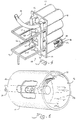
- the frame is in its fully extended or extended Position shown in Figure 2.
- Figure 2 are the nozzles 32 withdrawn to the rear panels, through which the tubes 30 are sealed with seals 52 extend.
- the tubes 30 are rotated at a speed high enough that the free ends 50 of the nozzles 32 essentially the entire surface area 26 cover when they are between their move positions shown in Figures 1 and 2.
- Vacuum or suction so that they their respective Clean inside 26 while in just move one of these directions. This will by directing the airflow from the vertical Blocks 42a and 42b to hose 38a reached by Directing the airflow from the vertical blocks 42c and 42d to hose 38b and by selective application of suction to hoses 38a and 38b.
- Suction power is accordingly by the suction source 34 the open throttle valve 36b to the suction nozzles of FIG Pipes provided on the vertical blocks 42c and 42d are arranged. Because the frame 28 in its fully extended position in Figure 2 is pulled, the nozzles clean their respective Inside pages 26. If the frame is its in Figure 2 reached position shown, the control mechanism returns 54 but the positions of the throttle valves 36a and 36b such that the remaining drum filters be cleaned when the frame is in its Position of Figure 1 returns. As in Figure 5 for example shown, a nozzle removes 32 filter material 58 from the inside 26 of a filter 14 if that Pipe 30 in the direction of the filter front end 16 emotional.
- the frame 28 is in a permanent operating position with respect to the drum filter grouping 12. That is, the frame does not move from one Grouping to another or from part of one Grouping to another during its operation.
- the frame can be removed for maintenance purposes or from a grouping or a grouping section can be removed for use in another. However, the frame does not move automatically from position to position along the group or from one grouping to another as part of it Operating.
- the frame 28 with respect to the grouping 12 by one Cross spindle construction reciprocating that through a motor 60 is driven.
- motor 60 drives a transmission assembly, which is housed in a gear box 62 and in turn rotates a shaft 64 which with a cross spindle 66 through a connection 67 connected is.
- the cross spindle 66 is through a Mother added that inside the case for the drum filter is fixed.
- a Rotation of the cross spindle 66 moves the frame 28 alternately axially towards the drum filter Grouping 12 and away from it between those in Figure 1 and 2 positions shown.
- the cross spindle arrangement allows the motor 60 in to be operated in one direction.
- the pipes 30 that driven by motor 60 rotate thereby in the same direction, throughout the pre and Backward movement of the frame.
- the nozzles 32 differ from their respective Extend the tubes straight out and at the Cross spindle 66 can be a single direction spindle act such that the motor 60 its Changes direction to move the frame.
- a Reversing the motor 60 to change direction can through a variety of suitable control mechanisms caused, for example, those that limit switches, Position detectors, contact switches, sequence clocks or have computer equipment, which the direction of the motor 60 based on the Move the position of the frame 28.
- a control device 54 can be used to operate from to control both the engine and the throttle valves.
- the forward and backward movement can of the frame 28 continuously or continuously be designed so that the filter 14 is continuously cleaned will.
- the Suction nozzles 32 are used to filter material from the Pull inside 26 or separate if the Frame yourself in one direction or in both directions emotional.
- FIG 4 Another configuration of the cross spindle assembly is shown in Figure 4, in which the frame 28th adjacent to the front ends 16 of the drum filter 14 is arranged so that the tubes 30 through the Extend front ends 16.
- the frame 28 has a moving portion 70 on a non-movable section 72 is attached by rods 74.
- the front wall 24 also as part of the frame 28 to serve.
- the cross spindle 66 can, for example, on the frame section 72, the front wall 24 or a housing the grouping 12 may be appropriate.
- the mother can received by the gear box 62 or otherwise be attached to a movable part of the frame and is rotated by the motor 60 so that the moving section 70 between one shown in Figure 4 indented position and one in FIG. 3 shown extended position moves.
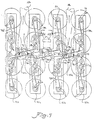
- the drive system for the pipes 30 is shown in FIG. 7 and 8 shown.
- the motor drives 60 a drive sprocket 76 through the gear box 62 on.
- the drive sprocket 76 is the drive sprocket 76 by a double sprocket, which has driven sprockets 77a and 77b, which drive belts or chains 78b and 78c.
- Tensioned by a series of idlers belts 78b and 78c drive sprockets 80 which in turn drive the tubes 30 ( Figure 1) to the To set nozzles 32 in rotation.
- Figure 7 shows a grouping of filters with four vertical columns.
- the system can be used to be any number of lines or To drive columns.
- the strap or chain 78b for a two-by-four grouping, as shown in Figure 4 to the opposite Side of the pulley 82 down to the pulley 84 are run.
- a similar arrangement would between the pulleys 86 and 88 with regard to the belt 78c.
- one of the hoses 38a and 38b (or both if a dual or double system is used, as explained above) on others Be placed on the frame 28 for example on a vertical element 42, such as shown in Figure 4.
- the connection connects the vertical Elements mechanically through the horizontal Element and allows air flow in between, for example through front channels 40 as in Figure 1 shown. Multiple columns can be added to the frame to groupings of different sizes to provide.
- the vertical elements can through a similar connection mechanism vertically be extended to provide additional rows. This construction represents a flexible cleaning system ready by a single motor can be driven.
- the tubes of the four-by-four grouping driven by four belts driven by four belts.
- the operation of belts 78b and 78c is above explained.
- the one with the vertical elements 42a and 42d are rotatably connected pipes, however driven by belts or chains 78a and 78d.
- the belt 78a is through a double sprocket 90 driven as shown in Figure 8B while the belt 78d is driven by a double sprocket 92 becomes as shown in Fig. 8C.
- An additional one vertical section can go to the vertical section 42a can be added, for example by the connection explained above and by returning of the belt 78a to the other side of the Tensioner pulley 94, around a double sprocket of a subsequent element.
- the belt and pulley assembly shown in Figure 7 is on the frame between the vertical ones Elements and the filter grouping.
- the Arrangement is different from the other figures for the sake of Clarity omitted. It is noted that more suitable drive arrangements can be used.
- FIG 6 Another preferred embodiment is shown in FIG 6, in which a single frame 28 two Groupings of tubes 30 carries in opposite directions Extend directions to back to back to provide lying filter groups 12.
- the frame 28 reciprocates as if through the Arrow 46 shown to filter both groups in the way explained above to clean.
- All of the tubes 30 are connected by a common belt and driven pulley system, such as shown in Figure 7, in which each Pair of opposing tubes 30 through a common one Sprocket 80 is driven ( Figure 7).
- There the belt and pulley system one side of the frame 28 can be arranged a set of tubes 30 extends through the vertical Elements for their respective drive sprockets 80. Accordingly, 32 tubes 30 from FIG. 6 can be driven by a single motor 60.
Abstract
Das Schwebstoff-Filtersystem weist eine Gruppierung (12) von Trommelfiltern (14) und einen Rahmen (20) auf, der in dauerhafter betriebsmäßiger Stellung benachbart zu der Gruppierung angeordnet ist. Mehrere längliche Elemente (30) sind betriebsmäßig auf dem Rahmen angeordnet und jedes längliche Element erstreckt sich in den inneren Bereich eines Trommelfilters. Eine Saugdüse (32) erstreckt sich von jedem länglichen Element um betriebsmäßig mit den Innenseitenbereich (26) des Trommelfilters zum Entfernen von Filtergut von diesem in Verbindung zu stehen. Ein Antriebsmechanismus befindet sich in betriebsmäßiger Verbindung mit den länglichen Elementen, um jedes dieser Elemente um seine Längsachse zu drehen und jedes dieser Elemente im wesentlichen entlang der Längsachse des Trommelfilters hin und her zu bewegen, von welchem sich das längliche Element so erstreckt, daß ein Saugende der Saugdüse im wesentlichen über die Innenseite des Filters bewegt wird. Eine Saugquelle befindet sich in betriebsmäßiger Verbindung mit jeder Saugdüse, um Saugkraft bzw. Unterdruck an die Saugdüsen so anzulegen, daß das Filtergut durch sie hindurch gezogen wird. <IMAGE>The suspended matter filter system has a group (12) of drum filters (14) and a frame (20) which is arranged in a permanent operational position adjacent to the grouping. A plurality of elongate members (30) are operatively located on the frame and each elongate member extends into the interior of a drum filter. A suction nozzle (32) extends from each elongated element to be operatively connected to the inside portion (26) of the drum filter for removing filter material therefrom. A drive mechanism is operatively connected to the elongate members to rotate each of these members about its longitudinal axis and to reciprocate each of these members substantially along the longitudinal axis of the drum filter, from which the elongate member extends so that a suction end the suction nozzle is moved essentially over the inside of the filter. A suction source is in operational connection with each suction nozzle in order to apply suction or negative pressure to the suction nozzles in such a way that the filter material is drawn through them. <IMAGE>
Description
Die vorliegende Erfindung betrifft eine Filteranordnung, die eine Gruppierung von trommelartigen Filtern aufweist, wobei Luft von der Innenseite jedes Filters zur Außenseite strömt. Die Filteranordnung weist ein System zum Entfernen von Filtergut von der Innenseite der trommelartigen Filter auf.The present invention relates to a filter arrangement, which is a grouping of drum-like filters having air from the inside of each filter flows to the outside. The filter arrangement has a System for removing filter material from the inside the drum-like filter.
Schwebstoff-Abfallmaterial, das in Industrieanlagen erzeugt wird, beispielsweise in der Textilindustrie, bei der Holzverarbeitung oder in anderen Systemen, bei welchen beträchtliche Anteile an Schwebstoffen oder Staub erzeugt werden, können durch unterschiedliche Arten von Filtersystemen ausgefiltert werden, beispielsweise solche, die große Trommelfilter- und Beutel- bzw. Sackfilteranordnungen enthalten. Bei herkömmlichen Trommelfiltern handelt es sich um große zylindrische Filter mit automatischen Abtrenn- bzw. Abstreifmechanismen zum Entfernen des Filterguts von der Trommel. Diese Filter erfordern jedoch umfangreichen Stellplatz. Sackfiltersysteme sind relativ sperrig und erfordern häufig eine manuelle Reinigung.HEPA waste material used in industrial plants is generated, for example in the textile industry, in wood processing or in other systems, at which considerable proportions of suspended matter or dust can be generated by different Types of filter systems are filtered out, for example, those that have large drum filters and Bag or bag filter assemblies included. At conventional drum filters are large cylindrical filters with automatic separation or Scraper mechanisms for removing the filter material from the drum. However, these filters require extensive Parking space. Bag filter systems are relative bulky and often require manual cleaning.
Mehrfach-Trommelfilter bieten einen kompakteren Aufbau, der eine große Menge an Schwebstoffen entfernen kann. Diese Filter weisen eine Gruppierung von kleinen trommelartigen Filtern auf, die in paralleler Gruppierung angeordnet sind. Jeder einzelne Trommelfilter ist wesentlich kleiner als der herkömmliche Trommelfilter. Beispielsweise kann eine einzige kleine Filtertrommel einer Mehrtrommelfilteranordnung ungefähr einen halben Meter Länge bei einem Durchmesser von ungefähr 40 Zentimetern aufweisen, wobei entsprechende Abmessungen für einen herkömmlichen Trommelfilter mehrere Füße betragen können. Die Filteranordnung führt zu einer relativ großen Gesamtreinigungsoberfläche in kompakter Ausbildung, die es der Gruppierung erlaubt, ein relativ großes Luftvolumen zu filtern, während sie relativ wenig Standplatz erfordert.Multiple drum filters offer a more compact one Structure that remove a large amount of suspended matter can. These filters have a grouping of small drum-like filters in parallel Grouping are arranged. Every single drum filter is much smaller than the conventional one Drum filter. For example, a single small filter drum of a multi-drum filter arrangement about half a meter in length with a diameter of about 40 centimeters, with corresponding Dimensions for a conventional drum filter can be several feet. The filter arrangement leads to a relatively large total cleaning surface in compact training it is the Grouping allows a relatively large volume of air filter while requiring relatively little space.
Jeder Filter in der Gruppierung ist ein Zylinder mit einem Filtermedium um sein äußeres herum. Bei dem Filtermaterial kann es sich um maschenartiges Material handeln, unterschiedliche gewobene oder Non-woven-Materialien oder um ein beliebiges geeignetes Medium, wie sich dem Fachmann auf diesem Gebiet der Technik erschließt. Schwebstoffe tragende Luft tritt in ein Ende der Trommel ein und wird durch das Umfangsfiltermaterial gezogen, wodurch auf den Filterinnenflächen Filtergut aufwächst.Each filter in the grouping is a cylinder with a filter medium around its exterior. In which Filter material can be mesh-like material trade different woven or non-woven materials or any suitable one Medium, as the expert in this field of Technology opens up. Air carrying suspended matter occurs into one end of the drum and is Circumferential filter material pulled, causing the Filter inner surfaces filter material grows up.
Ziel der Erfindung ist es, die vorstehend zum Stand der Technik erläuterten Nachteile zu überwinden. Eine Aufgabe der vorliegenden Erfindung besteht demnach darin, eine verbesserte Mehrtrommelfilteranordnung zu schaffen.The aim of the invention is to achieve the above to overcome the disadvantages explained in the art. A The object of the present invention is accordingly in an improved multi-drum filter arrangement create.
Eine weitere Aufgabe der vorliegenden Erfindung besteht darin, eine Mehrtrommelfilteranordnung mit einem automatischen Reinigungssystem zu schaffen, das ein verbessertes Antriebssystem aufweist.Another object of the present invention is in having a multi-drum filter assembly to create an automatic cleaning system that has an improved drive system.
Noch eine weitere Aufgabe der vorliegenden Erfindung besteht darin, eine Mehrtrommelfilteranordnung mit einem Reinigungssystem zu schaffen, das einen optimierten Saugdurchfluß aufweist.Yet another object of the present invention consists of having a multi-drum filter arrangement to create a cleaning system that optimizes Has suction flow.
Gelöst werden diese Aufgaben durch ein Filtersystem
für Schwebstoff-Abfallmaterial mit den Merkmalen des
Anspruchs 1, des Anspruchs 13, des Anspruchs 18, des
Anspruchs 19 und des Anspruchs 20. Vorteilhafte Weiterbildungen
sind in den Unteransprüchen angegeben. These tasks are solved by a filter system
for suspended matter waste material with the characteristics of
Demnach sieht die Erfindung vor, daß jeder Filter in der Gruppierung ein Vorderende aufweist, in welches Schwebstoffe tragende Luft strömt. Ein rückwärtiges Ende befindet sich in Längsrichtung gegenüberliegend zum Vorderende. Ein Filterabschnitt erstreckt sich zwischen dem Vorderende und dem rückwärtigen Ende derart, daß das Vorderende, das rückwärtige Ende und der Filterabschnitt einen Innenbereich des Trommelfilters festlegen. Ein Rahmen ist in permanenter betriebsmäßiger bzw. operativer Stellung benachbart zu der Trommelfiltergruppierung angeordnet. Jedes von mehreren länglichen Elementen ist auf dem Rahmen betriebsmäßig angeordnet und erstreckt sich in den Innenbereich des Trommelfilters. Jedes längliche Element weist eine Saugdüse auf, die sich von ihm erstreckt, um mit der Innenseite des zylindrischen Filterabschnitts des Trommelfilters zum Entfernen von Filtergut von dort in Verbindung zu stehen. Ein Antriebsmechanismus befindet sich in betriebsmäßiger Verbindung mit den länglichen Elementen, um jedes dieser Elemente um seine Längsachse zu drehen und jedes längliche Element im wesentlichen entlang der Längsachse des Trommelfilters hin und her zu bewegen, in welches es sich hinein erstreckt, so daß ein Saugende der Saugdüse im wesentlichen über die Innenseite des Filterabschnitts bewegt wird.Accordingly, the invention provides that each filter in the grouping has a front end into which Air carrying suspended matter flows. A backward one The end is opposite in the longitudinal direction to the front end. A filter section extends between the front end and the rear end such that the front end, the rear end and the filter section an inner region of the drum filter establish. A framework is in permanent operational or operational position adjacent to arranged the drum filter grouping. Each of Several elongated elements are operational on the frame arranged and extends into the interior of the drum filter. Any elongated element has a suction nozzle extending from it around with the inside of the cylindrical filter section the drum filter to remove Filter material to be connected from there. A drive mechanism is in operational Link with the elongated elements to each of these elements to rotate about its longitudinal axis and each elongated element essentially along the Moving the longitudinal axis of the drum filter back and forth, into which it extends so that a suction end the suction nozzle essentially over the inside of the filter section is moved.
Nachfolgend wird die Erfindung anhand der Zeichnung beispielhaft näher erläutert; es zeigen:
Figur 1- eine perspektivische Ansicht einer Ausführungsform des erfindungsgemäßen Filtersystems,
Figur 2- eine zweite perspektivische Ansicht der
Ausführungsform des in
Figur 1 gezeigten Filtersystems, Figur 3- eine perspektivische Ansicht einer weiteren Ausführungsform des erfindungsgemäßen Filtersystems,
- Figur 4
- eine perspektivische Ansicht einer weiteren Ausführungsform des erfindungsgemäßen Filtersystems,
Figur 5- eine vergrößerte Teilansicht eines erfindungsgemäß aufgebauten Filtersystems unter Darstellung eines Trommelfilters und einer Einrichtung zum Entfernen von Filtergut aus diesem,
- Figur 6
- eine perspektivische Ansicht einer weiteren Ausführungsform des erfindungsgemäßen Filtersystems,
Figur 7- eine Draufsicht einer Ausführungsform eines Antriebsmechanismus, der in Übereinstimmung mit dem erfindungsgemäßen Filtersystem bzw. für dieses aufgebaut ist,
- Figur 8A
- eine teilweise Draufsicht des Antriebsmechanismus
entlang den Linien 8A-8A in
Figur 7, - Figur 8B
- eine teilweise Draufsicht entlang den Linien
8B-8B in
Figur 7, und - Figur 8C
- eine teilweise Draufsicht entlang den Linien
8C-8C in
Figur 7.
- Figure 1
- 2 shows a perspective view of an embodiment of the filter system according to the invention,
- Figure 2
- 2 shows a second perspective view of the embodiment of the filter system shown in FIG. 1,
- Figure 3
- 2 shows a perspective view of a further embodiment of the filter system according to the invention,
- Figure 4
- 2 shows a perspective view of a further embodiment of the filter system according to the invention,
- Figure 5
- 2 shows an enlarged partial view of a filter system constructed according to the invention, showing a drum filter and a device for removing filter material from it,
- Figure 6
- 2 shows a perspective view of a further embodiment of the filter system according to the invention,
- Figure 7
- 3 shows a plan view of an embodiment of a drive mechanism which is constructed in accordance with the filter system according to the invention or for this,
- Figure 8A
- 7 is a partial top view of the drive mechanism along lines 8A-8A in FIG. 7,
- Figure 8B
- a partial plan view taken along lines 8B-8B in Figure 7, and
- Figure 8C
- a partial plan view taken along lines 8C-8C in Figure 7.
Analoge Merkmale und Elemente der vorliegenden Erfindung sind in den Zeichnungen mit denselben Bezugsziffern bezeichnet.Analog features and elements of the present invention are in the drawings with the same reference numerals designated.
Nunmehr wird im einzelnen auf aktuell bevorzugte Ausführungsformen der Erfindung Bezug genommen, von denen ein oder mehrere Beispiele in den beiliegenden Zeichnungen gezeigt sind. Jedes Beispiel dient zur Erläuterung der Erfindung, ohne daß diese hierauf beschränkt wäre. Tatsächlich erschließen sich dem Fachmann ohne weiteres Modifikationen und Abwandlungen, die an der vorliegenden Erfindung vorgenommen werden können, ohne von ihrem Umfang abzuweichen. Beispielsweise können als Teil einer Ausführungsform dargestellte und erläuterte Bestandteile in einer anderen bzw. weiteren Ausführungsform eingesetzt werden, um eine noch weitere Ausführungsform bereitzustellen. Es ist deshalb beabsichtigt, daß die vorliegende Erfindung diese Modifikationen und Abwandlungen als im Umfang der beiliegenden Ansprüche und ihrer Äquivalente liegend abdeckt.Now is in detail to currently preferred embodiments referred to the invention, of which one or more examples in the attached Drawings are shown. Each example is for Explanation of the invention without being limited to this would. In fact, the specialist can see without further modifications and modifications, which are made on the present invention can without deviating from their scope. For example can be shown as part of an embodiment and explained components in another or another embodiment are used to to provide yet another embodiment. It it is therefore intended that the present invention these modifications and variations as in scope the attached claims and their equivalents covers lying.
Die vorliegende Erfindung betrifft ein verbessertes
Filtersystem, beispielsweise zur Verwendung bei der
Textilverarbeitung. Figur 1 zeigt demnach eine aktuell
bevorzugte Ausführungsform eines Filtersystems,
das allgemein mit der Bezugsziffer 10 bezeichnet ist
und eine Gruppierung 12 von bzw. aus Trommelfiltern
14 aufweist. Jeder Trommelfilter 14 weist ein offenes
Vorderende 16 und ein geschlossenes rückwärtiges Ende
18 auf, das dem offenen Vorderende in Längsrichtung
gegenüberliegt. Ein allgemein zylindrisches Filtermaterial
20, das aus einem maschenartigen, gewobenen,
Nonwoven- bzw. nicht gewobenen oder anderen geeigneten
Materialien besteht, erstreckt sich zwischen dem
rückwärtigen Ende 18, das eine massive Platte umfassen
kann, und dem Vorderende 16. Obwohl die Platte am
rückwärtigen Ende 18 als flache kreisförmige Scheibe
dargestellt ist, versteht es sich, daß ein beliebiges
geeignetes Mittel zum Blockieren des Schwebstoffe
tragenden Luftstroms vom Trommelfilterinnern eingesetzt
werden kann.The present invention relates to an improved one
Filter system, for example for use in the
Textile processing. Figure 1 accordingly shows a current
preferred embodiment of a filter system,
which is generally designated by
Der Aufbau und die Arbeitsweise einer Trommelfiltergruppierung,
die bei der vorliegenden Erfindung verwendet
werden kann, ist im US Patent Nr. 5 114 444
offenbart, deren Offenbarungsinhalt hiermit zum Gegenstand
der vorliegenden Anmeldung erklärt wird.
Kurz gesagt, kann zylindrisches Filtermaterial 20 aus
zusammendrückbarem bzw. zusammenfaltbarem oder instabilem
Material aufgebaut sein, das einen Ring 22
(Figur 2) aufweist, der an seinem Vorderende angebracht
ist, und einen elastischen Strick, der um sein
rückwärtiges Ende angebracht ist. Das Filtermaterial
kann dadurch vom rückwärtigen Bereich der Gruppierung
durch Zusammendrücken der Klammer 22 eingetragen bzw.
geladen werden, indem es durch ein geeignetes Loch
einer Wand 24 eingeführt wird, wobei die Klammer so
freigegeben wird, daß sie in dem Loch festgesetzt
ist, wobei das Material über die Platte hinweg nach
hinten gezogen wird, welche das rückwärtige Ende 18
abdeckt, und wobei das Material so freigegeben wird,
daß der elastische Strick sich zusammenzieht, um das
Material um die Platte herum in Stellung zu halten.The structure and operation of a drum filter group,
used in the present invention
can be found in U.S. Patent No. 5,114,444
disclosed, the disclosure content hereby the subject
the present application is explained.
In short,
Das Vorderende 16 ist für Luftströmung offen.
Schwebstoffe tragende Luft strömt von einer stromaufwärtigen
Maschinenanordnung zur Wand 24. Der Luftstrom
kann stromaufwärts von der Wand 24 durch einen
Vorfilter teilweise gefiltert werden, wie sich dem
Fachmann erschließt. Diese Luft wird mittels Saugen
durch die Öffnungen in der Wand 24 in die Filter 14
und durch das zylindrische Material 20 jedes Filters
gezogen, wodurch die Schwebstoffe auf der Innenseite
26 des zylindrischen Filtermaterials gesammelt werden.The
Um die Innenseiten bzw. die inneren Oberflächen 26 zu
reinigen, trägt ein Rahmen 28 drehbar mehrere längliche
Elemente, wie etwa Rohre 30, welche Saugdüsen 32
aufweisen, die sich zu den Innenseiten 26 heraus erstrecken.
Das Saugen bzw. die Saugkraft bzw. den Unterdruck
wird von einer Saugquelle 24 an jede der Düsen
32 durch Drosselklappen 36a und 36b und durch
Schläuche 38a und 38b angelegt, wie in Figur 1, 5 und
7 durch Strömungspfeile dargestellt. Bei den
dargestellten Ausführungsformen strömt Filtergut von
der Innenseite 26 in eine Düse 32, durch ein Rohr 30
hindurch und in eine rückwärtige Kammer (die bei 40
in gestrichelten Linien gezeigt ist) von einem der
vertikalen Blöcke 42a bis 42d des Rahmens 28 hinein.
Daraufhin wird sie durch einen ähnlichen rückwärtigen
Abschnitt in einem horizontalen Block 44 zu einem
Schlauch 38a oder 38b zu einer Drosselklappe 36a oder
36b gezogen.To the inner sides or the
Damit die Düsen 32 Filtergut von im wesentlichen
sämtlichen Innenseitenbereichen 26 entfernen können,
bewegt sich der Rahmen 28 in bezug auf die Achsen der
Trommelfilter 14 vor und zurück, wie durch einen
Pfeil 46 dargestellt, während die Rohre 30 gedreht
werden, wie beispielsweise durch einen Pfeil 48 dargestellt.
Diese hin- und hergehende Bewegung des Rahmens
28 veranlaßt in Verbindung mit der Drehung der
Rohre 30 die freien Enden 50 der Düsen 32 dazu, einem
schraubenförmigen bzw. spiralförmigen Pfad über ihre
jeweiligen Innenseitenbereiche 26 zu folgen.So that the
Der Rahmen 28 ist in Figur 1 in einer vollständig
eingerückten Position gezeigt, in welcher die Rohre
30 vollständig in die Innenbereiche ihrer jeweiligen
Trommelfilter 14 eingeführt sind. Der Rahmen ist in
seiner vollständig ausgezogenen bzw. ausgefahrenen
Position in Figur 2 gezeigt. In Figur 2 sind die Düsen
32 zu den rückwärtigen Platten zurückgezogen,
durch welche die Rohre 30 sich mit Dichtungen 52
erstrecken.The
Die Rohre 30 werden mit einer Geschwindigkeit gedreht,
die hoch genug ist, daß die freien Enden 50
der Düsen 32 im wesentlichen die gesamten Oberflächenbereiche
26 abdecken, wenn sie sich zwischen ihren
in Figur 1 und 2 gezeigten Positionen bewegen. Um
den Luftströmungswirkungsgrad zu maximieren, legt die
in Figur 1 gezeigte Ausführungsform an die Düsen 32 The
Unterdruck bzw. Saugkraft derart an, daß sie ihre jeweiligen
Innenseiten 26 reinigen, während sie sich in
lediglich einer dieser Richtungen bewegen. Dies wird
durch Leiten des Luftstroms von den vertikalen
Blöcken 42a und 42b zum Schlauch 38a erreicht, durch
Leiten des Luftstroms von den vertikalen Blöcken 42c
und 42d zum Schlauch 38b und durch selektives Anlegen
von Saugkraft an die Schläuche 38a und 38b.Vacuum or suction so that they their respective
Clean inside 26 while in
just move one of these directions. this will
by directing the airflow from the
Wie in Figur 1 und durch die Luftströmungspfeile von
Figur 7 gezeigt, wird Luft in die rückwärtigen Kammern
40 der vertikalen Elemente 42a und 42b von ihren
jeweiligen Rohren 30 in das horizontale Element 44a
und dadurch in den Schlauch 38a hinein gezogen. Ein
ähnliches Luftströmungsmuster verläuft durch die vertikalen
Elemente 42c und 42d zum Schlauch 38b. Wenn
der Rahmen 28 sich in der vollständig eingerückten
Position befindet, wie in Figur 1 gezeigt, öffnet
eine Steuereinrichtung 54, welche Grenzschalter,
Zeitsteuerschaltungen wie Sequenztaktgeber oder Computereinrichtungen
aufweisen kann, die die Stellung
des Rahmens überwachen und vorhersagen, die
Drosselklappe 36b und schließt die Drosselklappe 36a
durch ein Relais 56. Die Steuereinrichtung 54 ist in
Figur 1 aus Gründen der Klarheit schematisch gezeigt.
Bei einer bevorzugten Ausführungsform ist sie jedoch
auf einem Rahmen 28 angeordnet und weist einen
Grenzschalter auf, um auf die Position des Rahmens zu
reagieren.As in Figure 1 and by the air flow arrows of
As shown in Figure 7, air is drawn into the
Saugkraft wird demnach von der Saugquelle 34 durch
die offene Drosselklappe 36b zu den Saugdüsen der
Rohre bereitgestellt, die auf den vertikalen Blöcken
42c und 42d angeordnet sind. Dadurch, daß der Rahmen
28 in seine vollständig ausgezogene Position in Figur
2 gezogen wird, reinigen die Düsen ihre jeweiligen
Innenseiten 26. Wenn der Rahmen seine in Figur 2
gezeigte Stellung erreicht, kehrt der Steuermechanismus
54 jedoch die Stellungen der Drosselklappen
36a und 36b derart um, daß die verbleibenden Trommelfilter
gereinigt werden, wenn der Rahmen in seine
Stellung von Figur 1 rückkehrt. Wie in Figur 5 beispielsweise
gezeigt, entfernt eine Düse 32 Filtergut
58 von der Innenseite 26 eines Filters 14, wenn das
Rohr 30 sich in Richtung auf das Filtervorderende 16
bewegt.Suction power is accordingly by the
Der Rahmen 28 befindet sich in dauerhafter Betriebsstellung
in bezug auf die Trommelfiltergruppierung
12. Das heißt, der Rahmen bewegt sich nicht von einer
Gruppierung zur anderen oder von einem Teil einer
Gruppierung zu einem anderen während seines Betriebs.
Der Rahmen kann zu Wartungszwecken entfernt werden
oder aus einer Gruppierung oder einem Gruppierungsabschnitt
zum Gebrauch in einem anderen entnommen werden.
Der Rahmen bewegt sich jedoch nicht automatisch
von Stellung zu Stellung entlang der Gruppierung oder
von einer Gruppierung zu einer anderen als Teil seines
Betriebs.The
Unter erneutem Bezug auf Figur 1 und 2 wird der Rahmen
28 in bezug auf die Gruppierung 12 durch einen
Kreuzspindel-Aufbau hin und her bewegt, der durch
einen Motor 60 angetrieben ist. Wie in Figur 8A
gezeigt, treibt der Motor 60 einen Getriebeaufbau an,
der in einer Getriebebox 62 untergebracht ist und
seinerseits eine Welle 64 in Drehung versetzt, die
mit einer Kreuzspindel 66 durch eine Verbindung 67
verbunden ist. Die Kreuzspindel 66 ist durch eine
Mutter aufgenommen, die innerhalb des Gehäuses für
die Trommelfilter festgelegt bzw. fixiert ist. Eine
Drehung der Kreuzspindel 66 bewegt den Rahmen 28 abwechselnd
axial in Richtung auf die Trommelfilter der
Gruppierung 12 und von dieser weg zwischen den in Figur
1 und 2 gezeigten Stellungen. Referring again to Figures 1 and 2, the
Die Kreuzspindelanordnung erlaubt es dem Motor 60, in
einer Richtung betrieben zu werden. Die Rohre 30, die
durch den Motor 60 angetrieben werden, drehen dadurch
in derselben Richtung, während der gesamten Vor- und
Rückbewegung des Rahmens. Es versteht sich jedoch,
daß weitere Konfigurationen möglich sind. Beispielsweise
können die Düsen 32 sich von ihren jeweiligen
Rohren geradewegs nach außen erstrecken und bei der
Kreuzspindel 66 kann es sich um eine Einzelrichtungs-Spindel
derart handeln, daß der Motor 60 seine
Richtung ändert, um den Rahmen zu bewegen. Ein
Umsteuern des Motors 60 zur Richtungsänderung kann
durch eine Vielzahl von geeigneten Steuermechanismen
bewirkt werden, beispielsweise solchen, die Grenzschalter,
Positionsdetektoren, Kontaktschalter, Sequenztaktgeber
oder Computereinrichtungen aufweisen,
welche die Richtung des Motors 60 auf Grundlage der
Stellung des Rahmens 28 bewegen. Eine Steuereinrichtung
54 kann verwendet werden, um den Betrieb von
sowohl dem Motor wie den Drosselklappen zu steuern.The cross spindle arrangement allows the
Bei jeder Konstruktion kann die Vor- und Rückbewegung
des Rahmens 28 durchgehend bzw. kontinuierlich so
ausgelegt sein, daß die Filter 14 kontinuierlich gereinigt
werden. Wie vorstehend erläutert, können die
Saugdüsen 32 verwendet werden, um Filtergut von den
Innenseiten 26 zu ziehen bzw. abzutrennen, wenn der
Rahmen sich in einer Richtung oder in beiden Richtungen
bewegt.With each construction the forward and backward movement can
of the
Eine andere Konfiguration des Kreuzspindel-Aufbaus
ist in Figur 4 gezeigt, bei welcher der Rahmen 28
benachbart zu den Vorderenden 16 der Trommelfilter 14
so angeordnet ist, daß die Rohre 30 sich durch die
Vorderenden 16 erstrecken. Bei dieser Ausführungsform
weist der Rahmen 28 einen sich bewegenden Abschnitt
70 auf, der an einem nicht beweglichen Abschnitt 72
durch Stangen 74 angebracht ist. In diesem Fall kann
die Vorderwand 24 auch als Teil des Rahmens 28
dienen.Another configuration of the cross spindle assembly
is shown in Figure 4, in which the frame 28th
adjacent to the front ends 16 of the
Die Kreuzspindel 66 kann beispielsweise am Rahmenabschnitt
72, der Vorderwand 24 oder einem Gehäuse
der Gruppierung 12 angebracht sein. Die Mutter kann
durch die Getriebebox 62 aufgenommen oder anderweitig
an einem beweglichen Teil des Rahmens angebracht sein
und wird durch den Motor 60 so gedreht, daß der sich
bewegende Abschnitt 70 zwischen einer in Figur 4 gezeigten
eingerückten Stellung und einer in Figur 3
gezeigten ausgefahrenen Stellung bewegt.The
Das Antriebssystem für die Rohre 30 ist in Figur 7
und 8 gezeigt. Wie in Figur 7 gezeigt, treibt der Motor
60 ein Antriebskettenrad 76 durch die Getriebebox
62 an. Wie in Figur 8A gezeigt, handelt es sich bei
dem Antriebskettenrad 76 um ein doppeltes Kettenrad,
das angetriebene Kettenräder 77a und 77b aufweist,
welche Riemen oder Ketten 78b und 78c antreiben.
Durch eine Reihe von Spannrollen gespannt, treiben
die Riemen 78b und 78c Antriebskettenräder 80 an, die
ihrerseits die Rohre 30 (Figur 1) antreiben, um die
Düsen 32 in Drehung zu versetzen.The drive system for the
Figur 7 zeigt eine Gruppierung von Filtern mit vier
vertikalen Spalten. Das System kann jedoch verwendet
werden, um eine beliebige Anzahl von Zeilen oder
Spalten anzutreiben. Beispielsweise kann der Riemen
oder die Kette 78b für eine zwei-mal-vier-Gruppierung,
wie in Figur 4 gezeigt, um die gegenüberliegende
Seite der Riemenscheibe 82 hinunter zur Riemenscheibe
84 laufengelassen werden. Eine ähnliche Anordnung
würde zwischen den Riemenscheiben 86 und 88
im Hinblick auf den Riemen 78c bewirkt werden.
Selbstverständlich muß einer der Schläuche 38a und
38b (oder beide, falls ein duales bzw. doppeltes System
verwendet wird, wie vorstehend erläutert) an anderer
Stelle auf dem Rahmen 28 angeordnet werden,
beispielsweise auf einem vertikalen Element 42, wie
in Figur 4 gezeigt. Außerdem müssen vertikale Elemente
erforderlichenfalls beispielsweise durch Anbringen
zusätzlicher horizontaler Elemente 44 an
einem vertikalen Endelement durch eine Verbindung
zwischen den horizontalen und vertikalen Elementen
hinzugefügt werden. Die Verbindung verbindet die vertikalen
Elemente mechanisch durch das horizontale
Element und ermöglicht eine Luftströmung dazwischen,
beispielsweise durch vordere Kanäle 40, wie in Figur
1 gezeigt. Mehrere Spalten können dem Rahmen hinzugefügt
werden, um Gruppierungen unterschiedlicher Grössen
bereitzustellen. Die vertikalen Elemente können
durch einen ähnlichen Verbindungsmechanismus vertikal
verlängert werden, um zusätzliche Zeilen bereitzustellen.
Diese Konstruktion stellt ein flexibles Reinigungssystem
bereit, das durch einen einzigen Motor
angetrieben werden kann.Figure 7 shows a grouping of filters with four
vertical columns. However, the system can be used
to be any number of lines or
To drive columns. For example, the strap
or chain 78b for a two-by-four grouping,
as shown in Figure 4 to the opposite
Side of the
Während die in Figur 7 gezeigte Konstruktion einen Rahmen mit vier Spalten und vier Zeilen aufweist, um eine Filtergruppierung mit sechzehn Trommeln bereitzustellen, wird demnach bemerkt, daß der Rahmen so konstruiert sein kann, daß eine beliebige Anzahl an Trommelfiltern bereitgestellt werden kann, und zwar sowohl als austauschbare wie nicht austauschbare Struktur. Außerdem kann das Reinigungssystem als gemeinsamer bzw. einheitlicher Block eingesetzt werden, der durch einen oder mehrere Motoren angetrieben wird, oder als diskrete Einheiten. Die spezielle Konfiguration hängt von verschiedenen Faktoren ab, wie etwa der Filtergruppierungsauslegung und dem Fassungsvermögen der Saugquelle oder der Saugquellen. Es versteht sich, daß sämtliche derartigen Konfigurationen innerhalb des Umfangs der vorliegenden Erfindung liegen. While the construction shown in Figure 7 a Frame with four columns and four rows to provide a filter grouping with sixteen drums, it is noted that the frame is so can be constructed that any number of Drum filters can be provided both interchangeable and non-interchangeable Structure. In addition, the cleaning system as a common or uniform block are used, which is powered by one or more motors will, or as discrete units. The special configuration depends on various factors such as about the filter grouping design and the capacity the suction source or sources. It it is understood that all such configurations within the scope of the present invention lie.
Unter erneutem Bezug auf Figur 7 werden die Rohre der
vier-mal-vier-Gruppierung durch vier Riemen angetrieben.
Der Betrieb der Riemen 78b und 78c ist vorstehend
erläutert. Die mit den vertikalen Elementen 42a
und 42d drehbar verbundenen Rohre werden jedoch jeweils
durch Riemen oder Ketten 78a und 78d angetrieben.
Der Riemen 78a wird durch ein doppeltes Kettenrad
90 angetrieben, wie in Figur 8B gezeigt, während
der Riemen 78d durch ein doppeltes Kettenrad 92 angetrieben
wird, wie in Fig. 8C gezeigt. Ein zusätzlicher
vertikaler Abschnitt kann zu dem vertikalen Abschnitt
42a hinzugefügt werden, beispielsweise durch
die vorstehend erläuterte Verbindung und durch Rückleiten
des Riemens 78a zu der anderen Seite der
Spannrolle 94, um daraufhin um ein doppeltes Kettenrad
eines sich anschließenden Elements herum zu verlaufen.Referring again to Figure 7, the tubes of the
four-by-four grouping driven by four belts.
The operation of belts 78b and 78c is above
explained. The one with the
Der in Figur 7 gezeigte Riemen- und Riemenscheibenaufbau ist auf dem Rahmen zwischen den vertikalen Elementen und der Filtergruppierung angeordnet. Die Anordnung ist von den anderen Figuren aus Gründen der Klarheit weggelassen. Es wird bemerkt, daß weitere geeignete Antriebsanordnungen verwendet werden können.The belt and pulley assembly shown in Figure 7 is on the frame between the vertical ones Elements and the filter grouping. The Arrangement is different from the other figures for the sake of Clarity omitted. It is noted that more suitable drive arrangements can be used.
Eine weitere bevorzugte Ausführungsform ist in Figur
6 gezeigt, bei welcher ein einziger Rahmen 28 zwei
Gruppierungen von Rohren 30 trägt, die sich in entgegengesetzten
Richtungen erstrecken, um Rücken an Rücken
liegende Filtergruppierungen 12 bereitzustellen.
Der Rahmen 28 bewegt sich hin und her, wie durch den
Pfeil 46 dargestellt, um beide Filtergruppierungen in
der vorstehend erläuterten Weise zu reinigen. Obwohl
in Figur 6 nicht gezeigt, erstrecken sich zwischen
jedem der Rohre 30 die in Figur 1 gezeigten Düsen 32,
um die Filter beider Gruppierungen zu reinigen. Sämtliche
der Rohre 30 werden durch ein gemeinsames Riemen-
und Riemenscheibensystem angetrieben, wie beispielsweise
in Figur 7 gezeigt, bei welchem jedes
Paar von gegenüberliegenden Rohren 30 durch ein gemeinsames
Kettenrad 80 angetrieben ist (Figur 7). Da
das Riemen- und Riemenscheibensystem dadurch auf
einer Seite des Rahmens 28 angeordnet werden kann,
erstreckt sich ein Satz von Rohren 30 durch die vertikalen
Elemente zu ihren jeweiligen Antriebskettenrädern
80. Demnach können 32 Rohre 30 von Figur 6
durch einen einzigen Motor 60 angetrieben werden.Another preferred embodiment is shown in FIG
6, in which a
Während bevorzugte Ausführungsformen der Erfindung vorstehend erläutert wurden, versteht es sich, daß beliebige äquivalente Realisierungen der vorliegenden Erfindung in ihrem Umfang liegen. Die dargestellten Ausführungsformen sind lediglich beispielhaft dargestellt und sollen keine Beschränkungen für die vorliegende Erfindung bilden. Beispielsweise können die vertikalen und horizontalen Elemente, die in den in den Figuren dargestellten Rahmen enthalten sind, durch andere geeignete Strukturen zum drehbaren Tragen der Rohre ersetzt sein, die sich in die Trommelfilter hinein erstrecken. Dem Fachmann auf diesem Gebiet der Technik erschließt sich damit, daß die vorliegende Erfindung nicht auf diese Ausführungsformen beschränkt ist, sondern Modifikationen zugänglich ist. Sämtliche derartigen Ausführungsformen fallen deshalb in den Äquivalenzbereich der anliegenden Ansprüche.While preferred embodiments of the invention have been explained above, it is understood that any equivalent realizations of the present Invention lie in its scope. The illustrated Embodiments are only shown as examples and are not intended to limit the present Form invention. For example, the vertical and horizontal elements included in the the frames shown in the figures are included, by other suitable structures for rotatable carrying the pipes to be replaced, which are in the drum filter extend into it. The specialist in this field the technology reveals that the present Invention does not apply to these embodiments is limited, but modifications accessible is. All such embodiments fall therefore within the equivalence range of the appended claims.
Claims (22)
Applications Claiming Priority (2)
| Application Number | Priority Date | Filing Date | Title |
|---|---|---|---|
| US08/823,807 US5814114A (en) | 1997-03-24 | 1997-03-24 | Airborne waste filter arrangement |
| US823807 | 1997-03-24 |
Publications (2)
| Publication Number | Publication Date |
|---|---|
| EP0868934A1 true EP0868934A1 (en) | 1998-10-07 |
| EP0868934B1 EP0868934B1 (en) | 2004-06-16 |
Family
ID=25239784
Family Applications (1)
| Application Number | Title | Priority Date | Filing Date |
|---|---|---|---|
| EP97121822A Expired - Lifetime EP0868934B1 (en) | 1997-03-24 | 1997-12-11 | Filter system for airborne particles |
Country Status (5)
| Country | Link |
|---|---|
| US (1) | US5814114A (en) |
| EP (1) | EP0868934B1 (en) |
| BR (1) | BR9704798A (en) |
| DE (1) | DE59711722D1 (en) |
| ES (1) | ES2221945T3 (en) |
Cited By (3)
| Publication number | Priority date | Publication date | Assignee | Title |
|---|---|---|---|---|
| DE202012002008U1 (en) | 2012-02-25 | 2012-04-04 | Ltg Aktiengesellschaft | Air filtration system |
| DE102012003824A1 (en) | 2012-02-25 | 2013-08-29 | Ltg Aktiengesellschaft | Air filtration system has rotary slide structure that is arranged downstream in suction chamber in the suction direction and is connected fluidically to suction device |
| CN104475399A (en) * | 2014-12-19 | 2015-04-01 | 江苏精亚环境科技有限公司 | Movable suction box |
Families Citing this family (10)
| Publication number | Priority date | Publication date | Assignee | Title |
|---|---|---|---|---|
| US6890365B2 (en) * | 2003-05-09 | 2005-05-10 | Dillman Equipment, Inc. | Reverse-flow baghouse |
| US7318249B2 (en) * | 2004-02-23 | 2008-01-15 | Kun Yi Lin | Vacuum collector having sweeping device |
| US7309366B2 (en) * | 2005-04-05 | 2007-12-18 | Jensen Robert M | Bag cleaning compressed air nozzle |
| DE102006000310A1 (en) * | 2006-06-26 | 2008-01-10 | Hilti Ag | dust extraction |
| US20090151306A1 (en) * | 2007-12-13 | 2009-06-18 | Chang Tjer Industrial Co., Ltd. | Dust removing device for dust collector |
| EP2244662B1 (en) * | 2008-01-28 | 2021-09-29 | Implantica Patent Ltd. | Blood clot removal device and system |
| CN107321088B (en) * | 2017-08-22 | 2018-07-03 | 新乡市新垣防腐保温制品有限公司 | A kind of high efficiency dust processor |
| GB2584410B (en) * | 2019-05-16 | 2022-12-07 | Dyson Technology Ltd | A filter assembly |
| KR102183820B1 (en) * | 2020-03-10 | 2020-11-30 | 주식회사 그레넥스 | Back wash device for fabric filtration apparatus |
| US20230405508A1 (en) * | 2022-06-20 | 2023-12-21 | William L McLean, Jr. | Air filter cleaning device |
Citations (4)
| Publication number | Priority date | Publication date | Assignee | Title |
|---|---|---|---|---|
| US4154588A (en) * | 1977-09-27 | 1979-05-15 | Herndon Marion E Jr | Cylindrical cell self-cleaning filter |
| US4289510A (en) * | 1980-01-21 | 1981-09-15 | Conor Corporation | Internal loading cylindrical filter with unsupported tubular filter fabric |
| EP0459307A2 (en) * | 1990-05-29 | 1991-12-04 | Ltg Lufttechnische Gmbh | Filtering device with a plurality of filtering tubes |
| US5571299A (en) * | 1995-04-28 | 1996-11-05 | Tonn; Harold H. | Dust collector |
Family Cites Families (8)
| Publication number | Priority date | Publication date | Assignee | Title |
|---|---|---|---|---|
| DE604096C (en) * | 1933-08-30 | 1934-10-15 | Heinrich Luehr | Bag filter |
| GB1077718A (en) * | 1963-05-29 | 1967-08-02 | Leesona Holt Ltd | Improvements in suction cleaning equipment for winding machines |
| US3606735A (en) * | 1969-07-01 | 1971-09-21 | Aeronca Inc | Air filter assembly providing increased filtering surface area for a given volumetric size |
| US4251237A (en) * | 1980-02-13 | 1981-02-17 | Smith Randall E | Air filter and method of filtering |
| JPS57153775A (en) * | 1981-03-16 | 1982-09-22 | Kikkoman Shoyu Co Ltd | Classifier |
| US4364755A (en) * | 1981-12-17 | 1982-12-21 | Hans Ferri | Filter assembly |
| US5453117A (en) * | 1994-03-22 | 1995-09-26 | Luwa Ag | Fluid filter and method of separating entrained particulate matter from a moving fluid stream |
| US5507851A (en) * | 1994-07-15 | 1996-04-16 | Kennington; H. L. | Filter cleaning apparatus |
-
1997
- 1997-03-24 US US08/823,807 patent/US5814114A/en not_active Expired - Lifetime
- 1997-09-23 BR BR9704798A patent/BR9704798A/en not_active IP Right Cessation
- 1997-12-11 ES ES97121822T patent/ES2221945T3/en not_active Expired - Lifetime
- 1997-12-11 DE DE59711722T patent/DE59711722D1/en not_active Expired - Lifetime
- 1997-12-11 EP EP97121822A patent/EP0868934B1/en not_active Expired - Lifetime
Patent Citations (5)
| Publication number | Priority date | Publication date | Assignee | Title |
|---|---|---|---|---|
| US4154588A (en) * | 1977-09-27 | 1979-05-15 | Herndon Marion E Jr | Cylindrical cell self-cleaning filter |
| US4289510A (en) * | 1980-01-21 | 1981-09-15 | Conor Corporation | Internal loading cylindrical filter with unsupported tubular filter fabric |
| EP0459307A2 (en) * | 1990-05-29 | 1991-12-04 | Ltg Lufttechnische Gmbh | Filtering device with a plurality of filtering tubes |
| US5114444A (en) * | 1990-05-29 | 1992-05-19 | Ltg Lufttechnische Gmbh | Filter arrangement including at least one drum-type filter |
| US5571299A (en) * | 1995-04-28 | 1996-11-05 | Tonn; Harold H. | Dust collector |
Cited By (4)
| Publication number | Priority date | Publication date | Assignee | Title |
|---|---|---|---|---|
| DE202012002008U1 (en) | 2012-02-25 | 2012-04-04 | Ltg Aktiengesellschaft | Air filtration system |
| DE102012003824A1 (en) | 2012-02-25 | 2013-08-29 | Ltg Aktiengesellschaft | Air filtration system has rotary slide structure that is arranged downstream in suction chamber in the suction direction and is connected fluidically to suction device |
| CN104475399A (en) * | 2014-12-19 | 2015-04-01 | 江苏精亚环境科技有限公司 | Movable suction box |
| CN104475399B (en) * | 2014-12-19 | 2017-01-11 | 江苏精亚环境科技有限公司 | Movable suction box |
Also Published As
| Publication number | Publication date |
|---|---|
| EP0868934B1 (en) | 2004-06-16 |
| US5814114A (en) | 1998-09-29 |
| DE59711722D1 (en) | 2004-07-22 |
| ES2221945T3 (en) | 2005-01-16 |
| BR9704798A (en) | 1998-12-01 |
Similar Documents
| Publication | Publication Date | Title |
|---|---|---|
| DE8503261U1 (en) | Self-cleaning filter device | |
| DE2917986C2 (en) | Standing filter device | |
| DE4017206C2 (en) | Filter arrangement with several drum filters | |
| EP0868934B1 (en) | Filter system for airborne particles | |
| DE1930117B2 (en) | FILTER UNIT FOR LIQUID | |
| DE2226687A1 (en) | Method for filtering a muddy material and device for carrying out the method | |
| CH652045A5 (en) | DEVICE FOR SEPARATING TAKEN PARTICULATE MATERIAL FROM A FLUID. | |
| DE2261642C3 (en) | Device for cleaning tubular filter elements | |
| DE1935153C3 (en) | Filter with a filter screen | |
| CH673591A5 (en) | ||
| DE3842867A1 (en) | DEVICE FOR REMOVING FILTER CAKES FROM A FILTER PRESS | |
| DE2846886A1 (en) | FILTER DEVICE | |
| DE102006036480A1 (en) | Air filter system and method for cleaning air | |
| DE2130326C3 (en) | Filter press | |
| EP0673665B1 (en) | Fluid filter and process for separating dust particles from a fluid stream | |
| DE2838945A1 (en) | BAND FILTER | |
| DE3830991A1 (en) | Filter apparatus and method for the operation thereof | |
| DE3939645C3 (en) | Dust separator with tubular filter elements and method for changing them | |
| EP0391091B1 (en) | Vacuum belt filtration apparatus | |
| DE3910930C2 (en) | ||
| DE19837775C2 (en) | Filter device | |
| DE2639493C2 (en) | Vacuum drum filter with automatically controlled transport of one or more belts in unison with the movement of the filter drum to filter out solids from liquids | |
| DE2839063C3 (en) | Fluid filter | |
| DE1407956A1 (en) | Dry filter cleaning system | |
| DE162091C (en) |
Legal Events
| Date | Code | Title | Description |
|---|---|---|---|
| PUAI | Public reference made under article 153(3) epc to a published international application that has entered the european phase |
Free format text: ORIGINAL CODE: 0009012 |
|
| AK | Designated contracting states |
Kind code of ref document: A1 Designated state(s): CH DE ES FR GB IT LI |
|
| 17P | Request for examination filed |
Effective date: 19990407 |
|
| AKX | Designation fees paid |
Free format text: CH DE ES FR GB IT LI |
|
| 17Q | First examination report despatched |
Effective date: 20020924 |
|
| GRAP | Despatch of communication of intention to grant a patent |
Free format text: ORIGINAL CODE: EPIDOSNIGR1 |
|
| GRAS | Grant fee paid |
Free format text: ORIGINAL CODE: EPIDOSNIGR3 |
|
| GRAA | (expected) grant |
Free format text: ORIGINAL CODE: 0009210 |
|
| AK | Designated contracting states |
Kind code of ref document: B1 Designated state(s): CH DE ES FR GB IT LI |
|
| REG | Reference to a national code |
Ref country code: GB Ref legal event code: FG4D Free format text: NOT ENGLISH |
|
| REG | Reference to a national code |
Ref country code: CH Ref legal event code: EP |
|
| REF | Corresponds to: |
Ref document number: 59711722 Country of ref document: DE Date of ref document: 20040722 Kind code of ref document: P |
|
| REG | Reference to a national code |
Ref country code: CH Ref legal event code: NV Representative=s name: TROESCH SCHEIDEGGER WERNER AG |
|
| GBT | Gb: translation of ep patent filed (gb section 77(6)(a)/1977) |
Effective date: 20040823 |
|
| REG | Reference to a national code |
Ref country code: ES Ref legal event code: FG2A Ref document number: 2221945 Country of ref document: ES Kind code of ref document: T3 |
|
| ET | Fr: translation filed | ||
| PLBE | No opposition filed within time limit |
Free format text: ORIGINAL CODE: 0009261 |
|
| STAA | Information on the status of an ep patent application or granted ep patent |
Free format text: STATUS: NO OPPOSITION FILED WITHIN TIME LIMIT |
|
| 26N | No opposition filed |
Effective date: 20050317 |
|
| REG | Reference to a national code |
Ref country code: CH Ref legal event code: PUE Owner name: LTG AEROB AIR ENGINEERING GMBH Free format text: LTG LUFTTECHNISCHE GMBH#WERNERSTRASSE 119-129#70435 STUTTGART (DE) -TRANSFER TO- LTG AEROB AIR ENGINEERING GMBH#HAERTLESAECKERSTRASSE 5#71336 WAIBLINGEN (DE) |
|
| REG | Reference to a national code |
Ref country code: GB Ref legal event code: 732E |
|
| REG | Reference to a national code |
Ref country code: FR Ref legal event code: TP |
|
| REG | Reference to a national code |
Ref country code: ES Ref legal event code: PC2A |
|
| PGFP | Annual fee paid to national office [announced via postgrant information from national office to epo] |
Ref country code: ES Payment date: 20091222 Year of fee payment: 13 Ref country code: CH Payment date: 20091224 Year of fee payment: 13 |
|
| PGFP | Annual fee paid to national office [announced via postgrant information from national office to epo] |
Ref country code: IT Payment date: 20091223 Year of fee payment: 13 Ref country code: GB Payment date: 20091218 Year of fee payment: 13 Ref country code: FR Payment date: 20100108 Year of fee payment: 13 |
|
| PGFP | Annual fee paid to national office [announced via postgrant information from national office to epo] |
Ref country code: DE Payment date: 20100123 Year of fee payment: 13 |
|
| REG | Reference to a national code |
Ref country code: CH Ref legal event code: PL |
|
| GBPC | Gb: european patent ceased through non-payment of renewal fee |
Effective date: 20101211 |
|
| REG | Reference to a national code |
Ref country code: FR Ref legal event code: ST Effective date: 20110831 |
|
| PG25 | Lapsed in a contracting state [announced via postgrant information from national office to epo] |
Ref country code: CH Free format text: LAPSE BECAUSE OF NON-PAYMENT OF DUE FEES Effective date: 20101231 Ref country code: LI Free format text: LAPSE BECAUSE OF NON-PAYMENT OF DUE FEES Effective date: 20101231 Ref country code: FR Free format text: LAPSE BECAUSE OF NON-PAYMENT OF DUE FEES Effective date: 20110103 |
|
| REG | Reference to a national code |
Ref country code: DE Ref legal event code: R119 Ref document number: 59711722 Country of ref document: DE Effective date: 20110701 |
|
| PG25 | Lapsed in a contracting state [announced via postgrant information from national office to epo] |
Ref country code: DE Free format text: LAPSE BECAUSE OF NON-PAYMENT OF DUE FEES Effective date: 20110701 Ref country code: GB Free format text: LAPSE BECAUSE OF NON-PAYMENT OF DUE FEES Effective date: 20101211 |
|
| PG25 | Lapsed in a contracting state [announced via postgrant information from national office to epo] |
Ref country code: IT Free format text: LAPSE BECAUSE OF NON-PAYMENT OF DUE FEES Effective date: 20101211 |
|
| REG | Reference to a national code |
Ref country code: ES Ref legal event code: FD2A Effective date: 20120220 |
|
| PG25 | Lapsed in a contracting state [announced via postgrant information from national office to epo] |
Ref country code: ES Free format text: LAPSE BECAUSE OF NON-PAYMENT OF DUE FEES Effective date: 20101212 |