EP0868720B1 - Zweischichtiges optisches medium mit einer teilreflektierenden goldlegierungschicht - Google Patents
Zweischichtiges optisches medium mit einer teilreflektierenden goldlegierungschicht Download PDFInfo
- Publication number
- EP0868720B1 EP0868720B1 EP96934085A EP96934085A EP0868720B1 EP 0868720 B1 EP0868720 B1 EP 0868720B1 EP 96934085 A EP96934085 A EP 96934085A EP 96934085 A EP96934085 A EP 96934085A EP 0868720 B1 EP0868720 B1 EP 0868720B1
- Authority
- EP
- European Patent Office
- Prior art keywords
- layer
- reflective layer
- alloy
- metal
- medium
- Prior art date
- Legal status (The legal status is an assumption and is not a legal conclusion. Google has not performed a legal analysis and makes no representation as to the accuracy of the status listed.)
- Expired - Lifetime
Links
Images

Classifications
-
- G—PHYSICS
- G11—INFORMATION STORAGE
- G11B—INFORMATION STORAGE BASED ON RELATIVE MOVEMENT BETWEEN RECORD CARRIER AND TRANSDUCER
- G11B7/00—Recording or reproducing by optical means, e.g. recording using a thermal beam of optical radiation by modifying optical properties or the physical structure, reproducing using an optical beam at lower power by sensing optical properties; Record carriers therefor
- G11B7/24—Record carriers characterised by shape, structure or physical properties, or by the selection of the material
- G11B7/241—Record carriers characterised by shape, structure or physical properties, or by the selection of the material characterised by the selection of the material
- G11B7/252—Record carriers characterised by shape, structure or physical properties, or by the selection of the material characterised by the selection of the material of layers other than recording layers
- G11B7/258—Record carriers characterised by shape, structure or physical properties, or by the selection of the material characterised by the selection of the material of layers other than recording layers of reflective layers
-
- G—PHYSICS
- G11—INFORMATION STORAGE
- G11B—INFORMATION STORAGE BASED ON RELATIVE MOVEMENT BETWEEN RECORD CARRIER AND TRANSDUCER
- G11B7/00—Recording or reproducing by optical means, e.g. recording using a thermal beam of optical radiation by modifying optical properties or the physical structure, reproducing using an optical beam at lower power by sensing optical properties; Record carriers therefor
- G11B7/24—Record carriers characterised by shape, structure or physical properties, or by the selection of the material
-
- G—PHYSICS
- G11—INFORMATION STORAGE
- G11B—INFORMATION STORAGE BASED ON RELATIVE MOVEMENT BETWEEN RECORD CARRIER AND TRANSDUCER
- G11B7/00—Recording or reproducing by optical means, e.g. recording using a thermal beam of optical radiation by modifying optical properties or the physical structure, reproducing using an optical beam at lower power by sensing optical properties; Record carriers therefor
- G11B7/08—Disposition or mounting of heads or light sources relatively to record carriers
- G11B7/09—Disposition or mounting of heads or light sources relatively to record carriers with provision for moving the light beam or focus plane for the purpose of maintaining alignment of the light beam relative to the record carrier during transducing operation, e.g. to compensate for surface irregularities of the latter or for track following
- G11B7/0908—Disposition or mounting of heads or light sources relatively to record carriers with provision for moving the light beam or focus plane for the purpose of maintaining alignment of the light beam relative to the record carrier during transducing operation, e.g. to compensate for surface irregularities of the latter or for track following for focusing only
-
- G—PHYSICS
- G11—INFORMATION STORAGE
- G11B—INFORMATION STORAGE BASED ON RELATIVE MOVEMENT BETWEEN RECORD CARRIER AND TRANSDUCER
- G11B7/00—Recording or reproducing by optical means, e.g. recording using a thermal beam of optical radiation by modifying optical properties or the physical structure, reproducing using an optical beam at lower power by sensing optical properties; Record carriers therefor
- G11B7/24—Record carriers characterised by shape, structure or physical properties, or by the selection of the material
- G11B7/241—Record carriers characterised by shape, structure or physical properties, or by the selection of the material characterised by the selection of the material
- G11B7/252—Record carriers characterised by shape, structure or physical properties, or by the selection of the material characterised by the selection of the material of layers other than recording layers
- G11B7/258—Record carriers characterised by shape, structure or physical properties, or by the selection of the material characterised by the selection of the material of layers other than recording layers of reflective layers
- G11B7/259—Record carriers characterised by shape, structure or physical properties, or by the selection of the material characterised by the selection of the material of layers other than recording layers of reflective layers based on silver
-
- G—PHYSICS
- G11—INFORMATION STORAGE
- G11B—INFORMATION STORAGE BASED ON RELATIVE MOVEMENT BETWEEN RECORD CARRIER AND TRANSDUCER
- G11B7/00—Recording or reproducing by optical means, e.g. recording using a thermal beam of optical radiation by modifying optical properties or the physical structure, reproducing using an optical beam at lower power by sensing optical properties; Record carriers therefor
- G11B7/24—Record carriers characterised by shape, structure or physical properties, or by the selection of the material
- G11B7/241—Record carriers characterised by shape, structure or physical properties, or by the selection of the material characterised by the selection of the material
- G11B7/252—Record carriers characterised by shape, structure or physical properties, or by the selection of the material characterised by the selection of the material of layers other than recording layers
- G11B7/258—Record carriers characterised by shape, structure or physical properties, or by the selection of the material characterised by the selection of the material of layers other than recording layers of reflective layers
- G11B7/2595—Record carriers characterised by shape, structure or physical properties, or by the selection of the material characterised by the selection of the material of layers other than recording layers of reflective layers based on gold
Definitions
- the present invention relates generally to the field of optical media, and more specifically to the area of optical media which employ two or more information storage layers.
- an alternative method for increasing the capacity of an optical disc is to employ additional storage layers on the disc which can be independently recorded or reproduced.
- the approach in this case is to increase the addressable area of the disc.
- This approach is attractive because it has the potential to substantially increase media storage capacity with only a modest increase in media and recording system complexity. If multiple storage layers, e.g., 2, are to be reproduced by optical beam(s) provided on one side of the disc, then one of the storage layers of the disc must be reflective enough so that it may be reproduced by the optical beam(s), but transparent enough so that the beam(s) may penetrate the first storage layer and pass on to a second storage layer.
- JP-A-62-042343 which is reflected in the preamble of claim 1 describes an optical disc having two information planes.
- Pits are formed on the first information plane, and a metal such as aluminum is vapor-deposited to the lower face so as to reflect light.
- the second information plane is formed by an aluminum thin film by photo etching so as to reflect the light at a part corresponding to a pit.
- the light corresponding to the information pit is reflected by the reflection of the pit on a track, and pit information is detected by an optical pickup.
- the light transmitted through a transmission part between the reflection part corresponding to the pit goes to the second information plane at the lower part and is reflected by the information plane at the lower part.
- the present invention provides an optical storage medium, like an optical disc, having a partially reflecting layer and a transparent spacer layer that allows a single reproducing optical beam to focus on either of two different planes within the disc.
- the disc includes a transparent substrate having a pattern of features, e.g., pits, in one of its sides.
- a partially reflective layer is provided adjacent the pattern of features.
- a transparent polymer spacer layer is provided over the partially reflective layer, and a highly reflective layer is provided over the spacer layer.
- the partially reflective layer includes a metal alloy including two metals, one of which is gold, and the other of which has an index of refraction having a real component, n, and an imaginary component, K, where n ⁇ 1 and K ⁇ 2 measured at 650 nm.
- the metal alloy has a general formula Au x M y , wherein 10 ⁇ x ⁇ 90 and 10 ⁇ y ⁇ 90, and M is the second metal.
- One preferred embodiment has n ⁇ 0.8 and K ⁇ 3 for the second metal.
- Another preferred embodiment has n ⁇ 0.65 and K ⁇ 3.5.
- the second metal is silver
- the metal alloy has a general formula Au x Ag y where 10 ⁇ x ⁇ 90 and 10 ⁇ y ⁇ 90.
- the second metal is copper.
- the metal alloy preferably has a general formula Au x Cu y , where 80 ⁇ x ⁇ 90 and 10 ⁇ y ⁇ 20.
- the metal alloy includes gold, silver, and copper and has a general formula Au x Ag y Cu z , where 20 ⁇ x ⁇ 75, 20 ⁇ y ⁇ 75, and 5 ⁇ z ⁇ 20.
- the substrate comprises polycarbonate and the spacer layer comprises a photopolymer.
- a second pattern of pits or features may be provided in the side of the spacer layer adjacent the highly reflective layer.
- the spacer layer preferably has a thickness within the range from about 5 to 100 ⁇ m.
- the present invention also includes optical storage systems which include the media described above.
- the systems further include a focused laser beam positioned to enter the medium through the substrate, means for adjusting the focal position of the laser beam on either the partially reflective or highly reflective layer, and a photodetector positioned to detect the reflected laser beam exiting the medium.
- the present invention also includes dual layer pre-recorded optical discs having the partially reflecting layer described above, as well as storage systems which incorporate such discs.
- FIGURE 1 shows an optical data storage system according to the present invention.
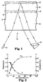
- FIGURE 2 is a graph of reflectance as a function of thickness for a partially reflecting layer of gold.
- FIGURE 3 is a graph of the real component (n) of the index of refraction as a function of the amount of silver in a thin film layer of a gold-silver alloy according to one embodiment of the present invention.
- FIGURE 4 is a graph of the real component (n) of the index of refraction as a function of the amount of copper in a thin film layer of a gold-copper alloy according to another embodiment of the present invention.
- FIGURE 1 An optical data storage system 10 according to the present invention is shown in FIGURE 1.
- Optical storage medium 12 comprises a transparent substrate 14, a partially reflective thin film layer 16 on a first data pit pattern 15, a transparent spacer layer 18, and a highly reflective thin film layer 20 on a second data pit pattern 19.
- An optical laser 30 emits an optical beam toward medium 12, as shown in FIGURE 1.
- Light from the optical beam which is reflected by either thin film layer 16 or 20 is sensed by detector 32, which senses modulations in light intensity based on the presence or absence of a pit in a particular spot on the thin film layers.
- patterns 15 and 19 are referred to as "data pit patterns," pit patterns 15 and 19 may be any pattern of pits or grooves that is capable of storing information, be it data, servo or tracking information, format information, etc.
- the capability for independently reading either the first or second pit pattern 15 or 19 is based on the comparatively limited focal depth characteristic of typical optical disc readout systems.
- the lenses employed in typical optical recorders/players to form a diffraction limited laser radiation spot on the media storage layer have moderately large (0.4 to 0.6) numerical apertures to improve resolution and increase storage density.
- Such lenses exhibit focal depths (i.e., the range of focus variation over which the focused spot size remains approximately diffraction limited) of about 2 ⁇ m; for large focus variations the size of the illuminated spot grows rapidly.
- the data pit patterns 15 and 19 on medium 10 can be reproduced most easily by first focusing on one of the reflective layers 16 or 20, and then reproducing the data on that entire layer before switching focal position to focus on the other reflective layer. In the alternative, it may be desirable to switch focus position one or more times before completely reproducing the data contained in one of data pit patterns 15 and 19. In either case, use of two data pit patterns separated by transparent layer 18 effectively doubles the data storage capacity of optical recording medium 10.
- An alternative construction may comprise two transparent substrates, each having a different molded or replicated data pit pattern on one surface.
- the metallic semi-reflector layer described herein is deposited on the first data pit pattern on a first substrate, and a highly reflective layer is deposited on the second data pit pattern on the second substrate.
- the two coated substrates are then bonded together with a transparent bonding agent (which can again be a photopolymer or other polymeric material) such that a uniform space is provided between the two bonded surfaces.
- a transparent bonding agent which can again be a photopolymer or other polymeric material
- Transparent substrate 14 may be a polymeric material suitable for optical disc substrates which supports molding of data pit pattern 15 with sufficient fidelity, such as polycarbonate or amorphous polyolefin.
- a flat substrate of, for example, glass or polymethylmethacrylate it is possible to use a flat substrate of, for example, glass or polymethylmethacrylate, and form data pit pattern 15 by means of photopolymer replication.
- Transparent spacer layer 18 may be a polymer, such as a photocurable polymer, which has a complex refractive index with a real component, n, ranging from about 1.45 to 1.6 and an imaginary component, K, of less than 10 -4 and more preferably less than 10 -5 .
- Transparent spacer layer 18 should be thick enough to allow laser 30 to focus on either of data pit patterns 15 and 19 with a minimum of cross-talk. This translates into a thickness that is preferably within the range of from about 5 to 100 ⁇ m, and more preferably from about 10 to 50 ⁇ m.
- Highly reflective layer 20 may be a metallic layer which exhibits high reflectivity at the laser wavelength used to reproduce the data.
- laser diode sources radiate at wavelengths ranging from about 600 to 850 nm.
- Aluminum, gold, silver, copper and their alloys can exhibit suitably high reflectivity in this wavelength range.
- Highly reflective layer 20 preferably has a reflectance of at least 70%, and more preferably at least 80%.
- the average readout signal levels from each of the data pit patterns 15 and 19 be approximately equal.
- the apparent reflectivities from layers 16 and 20, as seen by detector 32 should also be approximately equal.
- the term "apparent reflectivity" or “apparent reflectance” refers to the fraction of optical power incident upon transparent substrate 14 which, when focused to a spot on a flat region of either layer 16 or 20, could, in principle, be sensed by a photodetector in an optical readout device. It is assumed that the readout device comprises a laser, an appropriately designed optical path, and a photodetector. It is further assumed that the optical element in the optical path which is in closest proximity to transparent substrate 14 is a high (>0.4) numerical aperture objective lens.
- internal surface reflectivity or “internal interface reflectivity” refer to the fraction of optical power incident upon an interface within the media structure (e.g., the interface between transparent substrate 14 and partially reflecting layer 16 or the interface between spacer layer 18 and highly reflecting layer 20) which is reflected.
- highly reflective layer 20 consists of aluminum, which reflects about 80 to 85% of the light incident on the internal interface between spacer layer 18 and highly reflective layer 20. It is further assumed that the refractive index real component, n, of spacer layer 18 is 1.5, that substrate 14 is polycarbonate with a refractive index real component, n, of 1.57, and that reflections at the air-substrate interface do not contribute to the readout signal. If we further assume that partially reflecting layer 16 is an ideal material which exhibits no absorption, it can be shown that a reflectivity of about 0.35, as observed at the internal interface between substrate 14 and the partially reflecting layer will yield a balance in the apparent reflectivities from layers 16 and 20.
- the preceding examples define a range for the internal surface reflectivity at the interface between the substrate 14 and layer 16 of from about 0.25 to 0.35. Taking into account the attenuation due to reflections at the substrate-air interface, the above range corresponds to an apparent reflectivity seen by an optical readout device of about 0.24 to 0.33.
- a preferred material for partially reflecting layer 16 is gold.
- Gold is a desirable material because of its low real component of the index of refraction (n ⁇ 0.3) and its environmental stability (see Example 1).
- the disadvantage of using gold is its expense.
- Applicants have discovered that it is possible to alloy gold with another, less expensive metal in order to decrease the total cost of the partially reflecting layer.
- the alloying metal need not be as environmentally stable as gold (since the gold will lend environmental stability to the alloy).
- the alloying material should also have a low real component (n) of the index of refraction, like gold, so that the real component of the index of refraction is not substantially raised by the addition of the alloying element.
- the alloying material should be significantly less expensive than gold.
- the metal alloy of the partially reflecting layer should contain at least about 10, more preferably at least 15, and most preferably at least about 20 atomic % gold per 100 atomic % of the alloy to ensure the environmental stability of the alloy.
- the metal alloy preferably has a general formula Au x M y , where 10 ⁇ x ⁇ 90 and 10 ⁇ y ⁇ 90, and M is the second metal.
- the second metal M preferably has an index of refraction having a real component (n) and an imaginary component (K), where n ⁇ 1 and K ⁇ 2, more preferably n ⁇ 0.8 and K ⁇ 3, and most preferably n ⁇ 0.65 and K ⁇ 3.5 measured at 650 nm.
- One preferred metal for the second metal M is silver.
- the alloy has a preferred formula Au x Ag y where 10 ⁇ x ⁇ 90 and 10 ⁇ y ⁇ 90; more preferably 15 ⁇ x ⁇ 90 and 10 ⁇ y ⁇ 85; still more preferably 20 ⁇ x ⁇ 80 and 20 ⁇ y ⁇ 80; even more preferably 20 ⁇ x ⁇ 60 and 40 ⁇ y ⁇ 80; and most preferably 20 ⁇ x ⁇ 40 and 60 ⁇ y ⁇ 80.
- the second metal M may be copper.
- the alloy has a general formula Au x Cu y where 80 ⁇ x ⁇ 90 and 10 ⁇ y ⁇ 20. These ranges ensure the environmental stability of the alloy. It may also be desirable to alloy the gold with both silver and copper. Such an alloy would preferably have a general formula of Au x Ag y Cu z , where 20 ⁇ x ⁇ 75, 20 ⁇ y ⁇ 75, and 5 ⁇ z ⁇ 20.
- Partially reflecting layer 16 preferably has a thickness within the range of from about 8 to 14 nm and more preferably about 10 to 12 nm.
- R reflectance
- T transmission
- A absorption
- the absorption of the partially reflective layer is a function of the multiplicative product of the real and imaginary components, n and K, respectively, of the refractive index of the layer.
- the multiplicative product of n ⁇ K should be minimized. Since K is typically large for metals, it is essential to minimize n.
- Partially reflecting layer 16 preferably has an index of refraction such that n ⁇ 1 and K ⁇ 2, more preferably n ⁇ 0.8 and K ⁇ 3, and most preferably n ⁇ 0.65 and K ⁇ 3.5 measured at 650 nm.
- Thin films of Au were prepared by d.c. magnetron sputtering techniques onto glass slides and polycarbonate discs. Sputtering pressures were maintained at 2 mTorr and deposition rates for the Au were 7.8 nm/min. A series of Au films were deposited onto glass slides to determine the dependence of the reflectance/transmittance on film thickness at the 650 nm wavelength. This data was also used to extract the complex index of refraction of the Au films. FIGURE 2 depicts the dependence of the reflectance and transmittance upon the thickness of the film.
- Films of Ag x Au 100-x were prepared by co-depositing Ag and Au from individual magnetron sources. The depositions occurred in a vacuum system with a base pressure of 2x10 -7 Torr. Sputtering pressures were maintained at 2 mTorr and the combined deposition rates from the two sources ranged from 7 to 17 nm/min through the alloy range. The atomic composition of the alloy film was controlled by altering the deposition rates of the individual sources and cross checked by inductively-coupled plasma (ICP) composition measurements. Alloy films of a nominal thickness of 9-10 nm were deposited on glass slides to extract the components n and K of the index of refraction from measurements of the reflectance and transmittance. The dependence of the real component of the index of refraction on the content of Ag in the Ag-Au alloys is depicted in FIGURE 3.
- ICP inductively-coupled plasma
- the real part of the index of refraction (n) is less than 1.0 for any binary alloy of Ag and Au.
- the real and imaginary components of the refractive index have been used to determine the thickness of the alloy layer in a polycarbonate disc/ Ag x Au 100-x /photopolymer structure which would give a partial reflectance of at least 0.20 and have sufficient transmittance to achieve an apparent reflectance of at least 0.20 from the highly reflective layer.
- Table 2 lists the optical parameters of the alloy film, the thickness of the alloy layer used to make the disc samples, and the reflectance and transmittance of the resultant partial reflector sandwich structures, as measured on a spectrophotometer, for alloys containing from 10 to 60 atomic % Ag.
- the reflectance and transmittance of these discs satisfy the requirements that the partial reflectance is at least 0.20 with sufficient transmittance to achieve an apparent reflectance of at least 0.20 from the highly reflective layer.
- an alloy which has an index of refraction of n ⁇ 1.0 are the Au 100-x Cu x alloys.
- the Au-Cu alloy films were prepared by co-depositing Au and Cu from individual magnetron sputtering sources.
- the base pressures of the vacuum system was 2x10 -7 Torr and sputtering pressures were maintained at 2 mTorr.
- the combined deposition rates from the two sources ranged from 12 to 18 nm/min.
- the atomic composition of the alloys were varied by independently controlling the deposition rates of the Au and Cu sources and the compositions of selected Au-Cu alloys were cross checked by ICP measurements.
- Alloy film samples were first deposited onto glass slides with a nominal thickness of 10 nm for the determination of the optical properties n and K.
- FIGURE 4 depicts the variation of n on the atomic percentage of Cu.
- the optical constants from these films were then used to determine the required alloy film thickness in a polycarbonate disc/Au 100-x Cu x /photopolymer structure which would result in partial reflectance of at least 0.20 and have sufficient transmittance to achieve a reflectance of at least 0.20 from the highly reflective layer.
- Table 3 lists the optical parameters of the alloy, the thickness of the alloy layer, and the reflectance and transmittance of the resultant partial reflector discs as measured on a spectrophotometer.
- the data here indicates the reflectance and transmittance of these discs with Au-Cu alloy films satisfy the requirements that the partial reflectance is at least 0.20 with sufficient transmittance to achieve an apparent reflectance of at least 0.20 from the highly reflective layer.
Landscapes
- Optical Record Carriers And Manufacture Thereof (AREA)
- Optical Recording Or Reproduction (AREA)
Claims (12)
- Optisches Speichermedium (12) mit nacheinander:dadurch gekennzeichnet, daßeinem transparenten Substrat (14) mit einem Muster von Merkmalen (15) in einer Hauptfläche;einer an das Merkmalmuster angrenzenden teilreflektierenden Schicht (16), wobei die teilreflektierende Schicht ein Metall aufweist;einer transparenten Zwischenschicht (18); undeiner stark reflektierenden Schicht (20);die teilreflektierende Schicht (16) eine Metallegierung aus einem ersten Metall, das Gold ist, und einem zweiten Metall M aufweist, das einen Brechungsindex mit einer realen Komponente n und einer imaginären Komponente K aufweist, wobei bei 650nm n≤ 1 und K ≥2 sind, und wobei die Metallegierung die allgemeine Formel AuxMy hat, wobei 10< x< 90 und 10 < y< 90 sind.
- Optisches Speichermedium (12) nach Anspruch 1, wobei das zweite Metall M in der Metallegierung Silber ist und die Legierung einen Brechungsindex mit einer realen Komponente n und einer imaginären Komponente K aufweist, wobei bei 650nm n≤ 1 und K ≥2 sind.
- Optisches Speichermedium nach Anspruch 1 oder 2, wobei die transparente Zwischenschicht (18) eine Polymerschicht ist.
- Optisches Speichermedium nach Anspruch 2, wobei das optische Speichermedium eine zweischichtige vorgespeicherte optische Platte (12) ist;das transparente Substrat (14) ein erstes Datenpitmuster (15) in einer Hauptfläche aufweist;die an das erste Datenpitmuster angrenzende teilreflektierende Schicht (16) eine Legierung aus Gold und Silber mit der allgemeinen Formel AuxAgy ist, wobei 10< x< 60 und 40< y< 90 sind;die transparente Zwischenschicht (18) ein zweites Datenpitmuster (19) in einer Hauptfläche aufweist, wobei die Hauptfläche auf einer der teilreflektierenden Schicht abgewandten Seite der Zwischenschicht angeordnet ist; unddie stark reflektierende Schicht (20) angrenzend an das zweite Datenpitmuster angeordnet ist.
- Vorgespeichertes optisches Plattenspeichersystem (10) mit:einer vorgespeicherten optischen Platte (12) mit nacheinander:einem transparenten Substrat (14) mit einem ersten Datenpitmuster (15) in einer Hauptfläche;einer an das erste Datenpitmuster angrenzenden teilreflektierenden Schicht (16) aus einer Legierung aus Gold und Silber mit der allgemeinen Formel AuxAgy, wobei 15< x< 40 und 60< y< 85 sind;einer transparenten Zwischenschicht (18) mit einem zweiten Datenpitmuster (19) in einer Hauptfläche, wobei die Hauptfläche auf einer der teilreflektierenden Schicht abgewandten Seite der Zwischenschicht angeordnet ist;einer angrenzend an das zweite Datenpitmuster angeordneten stark reflektierenden Schicht (20);einem fokussierten Laserstrahl (30), der so angeordnet ist, daß er durch das Substrat in die Platte eindringen kann;einer Einrichtung zum Einstellen der Brennpunktposition des Laserstrahls, so daß der Strahl auf die teilreflektierende Schicht oder auf die stark reflektierende Schicht fokussiert werden kann; undeinem Photodetektor (32), der so angeordnet ist, daß er den von der Platte austretenden reflektierten Laserstrahl erfassen kann.
- Speichermedium nach einem der Ansprüche 1 bis 4, wobei n ≤ 0,65 und K ≥ 3,5 sind.
- Speichermedium nach einem der Ansprüche 1 bis 3, wobei 20< x< 80 und 20< y< 80 sind.
- Speichermedium nach einem der Ansprüche 1 bis 4, wobei 20< x< 40 und 60< y< 80 sind.
- Speichermedium nach Anspruch 1, wobei das zweite Metall Kupfer ist und die Metallegierung eine allgemeine Formel AuxCuy hat, wobei 80< x< 90 und 10< y< 20 sind.
- Speichermedium nach Anspruch 1, wobei das zweite Metall Silber ist und die Metallegierung außerdem Kupfer aufweist, und wobei die Metallegierung eine allgemeine Formel AuxAgyCuz aufweist, wobei 20< x< 75, 20< y< 75 und 5< z< 20 sind.
- Speichermedium nach einem der Ansprüche 1 bis 4 oder System nach Anspruch 5, wobei die Zwischenschicht eine Dicke im Bereich von 5 bis 100 µm hat.
- Speichermedium nach einem der Ansprüche 1 bis 4 oder System nach Anspruch 5, wobei die teilreflektierende Schicht eine Dicke von 8 bis 14 nm hat.
Applications Claiming Priority (3)
| Application Number | Priority Date | Filing Date | Title |
|---|---|---|---|
| US08/574,680 US5640382A (en) | 1995-12-19 | 1995-12-19 | Dual layer optical medium having partially reflecting metal alloy layer |
| US574680 | 1995-12-19 | ||
| PCT/US1996/016046 WO1997022968A1 (en) | 1995-12-19 | 1996-10-07 | Dual layer optical medium having partially reflecting gold alloy layer |
Publications (2)
| Publication Number | Publication Date |
|---|---|
| EP0868720A1 EP0868720A1 (de) | 1998-10-07 |
| EP0868720B1 true EP0868720B1 (de) | 2000-01-26 |
Family
ID=24297169
Family Applications (1)
| Application Number | Title | Priority Date | Filing Date |
|---|---|---|---|
| EP96934085A Expired - Lifetime EP0868720B1 (de) | 1995-12-19 | 1996-10-07 | Zweischichtiges optisches medium mit einer teilreflektierenden goldlegierungschicht |
Country Status (7)
| Country | Link |
|---|---|
| US (1) | US5640382A (de) |
| EP (1) | EP0868720B1 (de) |
| JP (1) | JP2000502482A (de) |
| KR (1) | KR20000064459A (de) |
| AU (1) | AU7258896A (de) |
| DE (1) | DE69606435T2 (de) |
| WO (1) | WO1997022968A1 (de) |
Families Citing this family (38)
| Publication number | Priority date | Publication date | Assignee | Title |
|---|---|---|---|---|
| US6160787A (en) * | 1996-01-11 | 2000-12-12 | Wea Manufacturing, Inc. | Multiple layer optical recording medium for use with two different wavelength laser beams |
| US6678237B1 (en) | 1997-03-27 | 2004-01-13 | Imation Corp. | Dual layer optical storage medium having partially reflecting layer comprising amorphous selenium |
| US6628603B1 (en) | 1997-03-27 | 2003-09-30 | Imation Corp. | Dual layer optical storage medium having partially reflecting layer comprising antimony sulfide |
| US6205112B1 (en) | 1998-02-17 | 2001-03-20 | Gateway, Inc. | Multipurpose optical disc having different formats on opposing sides |
| JPH11296904A (ja) | 1998-04-03 | 1999-10-29 | Toshiba Corp | 情報記録媒体およびこれに用いられる樹脂基板の製造方法 |
| US6544616B2 (en) | 2000-07-21 | 2003-04-08 | Target Technology Company, Llc | Metal alloys for the reflective or the semi-reflective layer of an optical storage medium |
| US6905750B2 (en) * | 1998-06-22 | 2005-06-14 | Target Technology Company, Llc | Metal alloys for the reflective or the semi-reflective layer of an optical storage medium |
| US6790503B2 (en) * | 1998-06-22 | 2004-09-14 | Target Technology Company, Llc | Metal alloys for the reflective or the semi-reflective layer of an optical storage medium |
| US6451402B1 (en) | 1998-06-22 | 2002-09-17 | Target Technology Company, Llc | Metal alloys for the reflective or the semi-reflective layer of an optical storage medium |
| US6007889A (en) | 1998-06-22 | 1999-12-28 | Target Technology, Llc | Metal alloys for the reflective or the semi-reflective layer of an optical storage medium |
| US7045187B2 (en) * | 1998-06-22 | 2006-05-16 | Nee Han H | Metal alloys for the reflective or the semi-reflective layer of an optical storage medium |
| US6764735B2 (en) | 1998-06-22 | 2004-07-20 | Target Technology Company, Llc | Metal alloys for the reflective or the semi-reflective layer of an optical storage medium |
| US7314657B2 (en) * | 2000-07-21 | 2008-01-01 | Target Technology Company, Llc | Metal alloys for the reflective or the semi-reflective layer of an optical storage medium |
| US7384677B2 (en) | 1998-06-22 | 2008-06-10 | Target Technology Company, Llc | Metal alloys for the reflective or semi-reflective layer of an optical storage medium |
| US6852384B2 (en) * | 1998-06-22 | 2005-02-08 | Han H. Nee | Metal alloys for the reflective or the semi-reflective layer of an optical storage medium |
| US6351446B1 (en) | 1998-10-02 | 2002-02-26 | Unaxis Balzers Aktiengesellschaft | Optical data storage disk |
| WO2000021079A2 (de) * | 1998-10-02 | 2000-04-13 | Unaxis Balzers Aktiengesellschaft | Optische datenspeicherscheibe |
| US6292457B1 (en) * | 1999-03-31 | 2001-09-18 | Eastman Kodak Company | Recordable optical media with a silver-gold reflective layer |
| JP3725412B2 (ja) * | 1999-11-19 | 2005-12-14 | Tdk株式会社 | 光記録媒体 |
| US7314659B2 (en) * | 2000-07-21 | 2008-01-01 | Target Technology Company, Llc | Metal alloys for the reflective or semi-reflective layer of an optical storage medium |
| US7018696B2 (en) * | 2003-04-18 | 2006-03-28 | Target Technology Company Llc | Metal alloys for the reflective or the semi-reflective layer of an optical storage medium |
| US7316837B2 (en) * | 2000-07-21 | 2008-01-08 | Target Technology Company, Llc | Metal alloys for the reflective or the semi-reflective layer of an optical storage medium |
| US7374805B2 (en) * | 2000-07-21 | 2008-05-20 | Target Technology Company, Llc | Metal alloys for the reflective or the semi-reflective layer of an optical storage medium |
| US6944115B2 (en) * | 2000-09-29 | 2005-09-13 | General Electric Company | Colored data storage media |
| JP2002170276A (ja) * | 2000-12-01 | 2002-06-14 | Pioneer Electronic Corp | 光学式多層情報記録媒体 |
| US6475588B1 (en) | 2001-08-07 | 2002-11-05 | General Electric Company | Colored digital versatile disks |
| US6475589B1 (en) | 2001-12-17 | 2002-11-05 | General Electric Company | Colored optical discs and methods for making the same |
| AU2003245661A1 (en) * | 2002-06-28 | 2004-01-19 | Williams Advanced Materials, Inc. | Corrosion resistive silver metal alloys for optical data storage and recordable storage media containing same |
| US7572517B2 (en) * | 2002-07-08 | 2009-08-11 | Target Technology Company, Llc | Reflective or semi-reflective metal alloy coatings |
| US20040005432A1 (en) * | 2002-07-08 | 2004-01-08 | Ridout James W. | Reflective or semi-reflective metal alloy coatings |
| US7889608B2 (en) * | 2002-11-29 | 2011-02-15 | Victor Company Of Japan, Ltd. | Information-signal recording and reproducing apparatus, related method, and related computer program |
| US20040268379A1 (en) * | 2003-06-30 | 2004-12-30 | Imation Corp. | Storage media volumetric factor |
| JP3793770B2 (ja) * | 2003-08-22 | 2006-07-05 | 株式会社リコー | 媒体特性規定方法 |
| TW200514070A (en) * | 2003-09-03 | 2005-04-16 | Williams Advanced Materials Inc | Silver alloys for optical data storage and optical media containing same |
| US20070014963A1 (en) * | 2005-07-12 | 2007-01-18 | Nee Han H | Metal alloys for the reflective layer of an optical storage medium |
| CN101371304B (zh) * | 2006-01-18 | 2011-09-14 | 三菱化学媒体株式会社 | 光记录介质 |
| US7613869B2 (en) * | 2006-11-27 | 2009-11-03 | Brigham Young University | Long-term digital data storage |
| WO2009126166A1 (en) * | 2008-04-11 | 2009-10-15 | Hewlett-Packard Development Company, L.P. | Optical data recording medium including a multi-layered markable coating |
Family Cites Families (25)
| Publication number | Priority date | Publication date | Assignee | Title |
|---|---|---|---|---|
| US3946367A (en) * | 1972-12-20 | 1976-03-23 | Videonics Of Hawaii, Inc. | Three dimensional electro-optical retrieval system |
| US4219704A (en) * | 1974-10-21 | 1980-08-26 | Eli S. Jacobs | Record playback apparatus for optical data records |
| NL7803069A (nl) * | 1978-03-22 | 1979-09-25 | Philips Nv | Meerlaags informatieschijf. |
| US4385372A (en) * | 1981-05-01 | 1983-05-24 | Drexler Technology Corporation | Reflective optical data storage and laser recording media having grooved dielectric encoded prerecorded information |
| NL8204291A (nl) * | 1982-11-05 | 1984-06-01 | Philips Nv | Optisch registratie-element. |
| US4735878A (en) * | 1985-03-12 | 1988-04-05 | Quixote Corporation | Optically read recording medium and method for making same |
| JPS6242343A (ja) * | 1985-07-23 | 1987-02-24 | Nippon Columbia Co Ltd | 光デイスク及びその再生装置 |
| JP2667164B2 (ja) * | 1986-12-09 | 1997-10-27 | 大日本印刷株式会社 | 光記録媒体 |
| JPS63102031U (de) * | 1986-12-22 | 1988-07-02 | ||
| JPH0823941B2 (ja) * | 1988-11-08 | 1996-03-06 | パイオニア株式会社 | 光学式情報記録担体及びその製造方法 |
| US5171392A (en) * | 1988-11-08 | 1992-12-15 | Pioneer Electronic Corporation | Method of producing an optical information record carrier |
| CA2017284C (en) * | 1989-07-04 | 1995-10-03 | Kazutomi Suzuki | Optical recording medium |
| US5303225A (en) * | 1989-10-30 | 1994-04-12 | Matsushita Electrical Industrial Co., Ltd. | Multi-layered optical disk with track and layer identification |
| JP2514261B2 (ja) * | 1990-01-11 | 1996-07-10 | 松下電器産業株式会社 | 光情報媒体、その製造方法、及びそのカセットケ―ス |
| JP2788777B2 (ja) * | 1990-03-02 | 1998-08-20 | パイオニア株式会社 | 光ピックアップ |
| JPH04193586A (ja) * | 1990-11-28 | 1992-07-13 | Ricoh Co Ltd | 光記録媒体 |
| US5255262A (en) * | 1991-06-04 | 1993-10-19 | International Business Machines Corporation | Multiple data surface optical data storage system with transmissive data surfaces |
| US5202875A (en) * | 1991-06-04 | 1993-04-13 | International Business Machines Corporation | Multiple data surface optical data storage system |
| JPH056571A (ja) * | 1991-06-28 | 1993-01-14 | Pioneer Electron Corp | 光学式情報記録媒体 |
| US5251198A (en) * | 1992-05-29 | 1993-10-05 | Strickler James H | Reading device for multi-layered optical information carrier |
| JPH06155921A (ja) * | 1992-11-25 | 1994-06-03 | Pioneer Electron Corp | 光記録媒体 |
| JPH06187662A (ja) * | 1992-12-18 | 1994-07-08 | Hitachi Ltd | 光記録媒体 |
| TW259865B (de) * | 1993-12-15 | 1995-10-11 | Ibm | |
| US5540966A (en) * | 1994-08-05 | 1996-07-30 | Minnesota Mining And Manufacturing Company | Dual layer optical medium having partially reflecting thin film layer |
| DE69520920T2 (de) * | 1994-10-03 | 2001-09-27 | Matsushita Electric Industrial Co., Ltd. | Optisches Informationsmedium, sowie Einheit und Verfahren zu dessen Herstellung |
-
1995
- 1995-12-19 US US08/574,680 patent/US5640382A/en not_active Expired - Lifetime
-
1996
- 1996-10-07 DE DE69606435T patent/DE69606435T2/de not_active Expired - Fee Related
- 1996-10-07 JP JP9522767A patent/JP2000502482A/ja active Pending
- 1996-10-07 AU AU72588/96A patent/AU7258896A/en not_active Abandoned
- 1996-10-07 KR KR1019980704629A patent/KR20000064459A/ko not_active Withdrawn
- 1996-10-07 WO PCT/US1996/016046 patent/WO1997022968A1/en not_active Ceased
- 1996-10-07 EP EP96934085A patent/EP0868720B1/de not_active Expired - Lifetime
Also Published As
| Publication number | Publication date |
|---|---|
| WO1997022968A1 (en) | 1997-06-26 |
| KR20000064459A (ko) | 2000-11-06 |
| EP0868720A1 (de) | 1998-10-07 |
| DE69606435D1 (de) | 2000-03-02 |
| US5640382A (en) | 1997-06-17 |
| AU7258896A (en) | 1997-07-14 |
| DE69606435T2 (de) | 2000-09-14 |
| JP2000502482A (ja) | 2000-02-29 |
Similar Documents
| Publication | Publication Date | Title |
|---|---|---|
| EP0868720B1 (de) | Zweischichtiges optisches medium mit einer teilreflektierenden goldlegierungschicht | |
| EP0775357B1 (de) | Doppelschichtiges optisches medium mit einer teilreflektierenden dünnfilmschicht | |
| WO1996004650B1 (en) | Dual layer optical medium having partially reflecting thin film layer | |
| CA2335844A1 (en) | Optical disk and method of manufacture thereof | |
| KR100894972B1 (ko) | 광학 기록 매체 | |
| US6678237B1 (en) | Dual layer optical storage medium having partially reflecting layer comprising amorphous selenium | |
| US5689497A (en) | Optical registration medium with dual information layer | |
| US6628603B1 (en) | Dual layer optical storage medium having partially reflecting layer comprising antimony sulfide | |
| US7842366B2 (en) | Multi-layer optical information recording medium | |
| EP1576599B1 (de) | Verwendung eines doppeltschichtigen photolithographischen resists als neues material für optische speicherung | |
| US5812182A (en) | Optical information recording medium for recording erasing and play back of compact disc signals | |
| MXPA98004908A (es) | Medio optico de capa dual que tiene una capa dealeacion de oro parcialmente reflectante | |
| US7014904B2 (en) | Optical information recording medium and method for manufacturing the medium | |
| CN1205792A (zh) | 具有部分反射金合金层的双层光学介质 | |
| EP1369858A1 (de) | Optischs platte | |
| KR100421862B1 (ko) | 박막 광디스크 | |
| KR100186544B1 (ko) | 고밀도 광디스크 및 그의 제조방법 | |
| KR100200875B1 (ko) | 이층 광디스크의 포커싱 서보방법 | |
| JPH10334507A (ja) | 光情報記録媒体 | |
| JPH06195753A (ja) | 光情報記録媒体 | |
| WO2005041181A1 (ja) | 光記録ディスク | |
| JPH11123873A (ja) | 光記録媒体 | |
| KR20020005324A (ko) | 고밀도 광디스크 | |
| JPH10188350A (ja) | 情報記録媒体 | |
| HK1062351B (en) | Optical disk |
Legal Events
| Date | Code | Title | Description |
|---|---|---|---|
| PUAI | Public reference made under article 153(3) epc to a published international application that has entered the european phase |
Free format text: ORIGINAL CODE: 0009012 |
|
| 17P | Request for examination filed |
Effective date: 19980715 |
|
| AK | Designated contracting states |
Kind code of ref document: A1 Designated state(s): DE FR GB IE IT NL |
|
| 17Q | First examination report despatched |
Effective date: 19981005 |
|
| GRAG | Despatch of communication of intention to grant |
Free format text: ORIGINAL CODE: EPIDOS AGRA |
|
| GRAG | Despatch of communication of intention to grant |
Free format text: ORIGINAL CODE: EPIDOS AGRA |
|
| GRAH | Despatch of communication of intention to grant a patent |
Free format text: ORIGINAL CODE: EPIDOS IGRA |
|
| GRAH | Despatch of communication of intention to grant a patent |
Free format text: ORIGINAL CODE: EPIDOS IGRA |
|
| GRAA | (expected) grant |
Free format text: ORIGINAL CODE: 0009210 |
|
| AK | Designated contracting states |
Kind code of ref document: B1 Designated state(s): DE FR GB IE IT NL |
|
| PG25 | Lapsed in a contracting state [announced via postgrant information from national office to epo] |
Ref country code: NL Free format text: LAPSE BECAUSE OF FAILURE TO SUBMIT A TRANSLATION OF THE DESCRIPTION OR TO PAY THE FEE WITHIN THE PRESCRIBED TIME-LIMIT Effective date: 20000126 Ref country code: IT Free format text: LAPSE BECAUSE OF FAILURE TO SUBMIT A TRANSLATION OF THE DESCRIPTION OR TO PAY THE FEE WITHIN THE PRE;WARNING: LAPSES OF ITALIAN PATENTS WITH EFFECTIVE DATE BEFORE 2007 MAY HAVE OCCURRED AT ANY TIME BEFORE 2007. THE CORRECT EFFECTIVE DATE MAY BE DIFFERENT FROM THE ONE RECORDED.SCRIBED TIME-LIMIT Effective date: 20000126 Ref country code: FR Free format text: LAPSE BECAUSE OF FAILURE TO SUBMIT A TRANSLATION OF THE DESCRIPTION OR TO PAY THE FEE WITHIN THE PRESCRIBED TIME-LIMIT Effective date: 20000126 |
|
| REF | Corresponds to: |
Ref document number: 69606435 Country of ref document: DE Date of ref document: 20000302 |
|
| REG | Reference to a national code |
Ref country code: IE Ref legal event code: FG4D |
|
| EN | Fr: translation not filed | ||
| NLV1 | Nl: lapsed or annulled due to failure to fulfill the requirements of art. 29p and 29m of the patents act | ||
| PGFP | Annual fee paid to national office [announced via postgrant information from national office to epo] |
Ref country code: GB Payment date: 20000918 Year of fee payment: 5 |
|
| PG25 | Lapsed in a contracting state [announced via postgrant information from national office to epo] |
Ref country code: IE Free format text: LAPSE BECAUSE OF NON-PAYMENT OF DUE FEES Effective date: 20001009 |
|
| PLBE | No opposition filed within time limit |
Free format text: ORIGINAL CODE: 0009261 |
|
| STAA | Information on the status of an ep patent application or granted ep patent |
Free format text: STATUS: NO OPPOSITION FILED WITHIN TIME LIMIT |
|
| 26N | No opposition filed | ||
| REG | Reference to a national code |
Ref country code: IE Ref legal event code: MM4A |
|
| PG25 | Lapsed in a contracting state [announced via postgrant information from national office to epo] |
Ref country code: GB Free format text: LAPSE BECAUSE OF NON-PAYMENT OF DUE FEES Effective date: 20011007 |
|
| PGFP | Annual fee paid to national office [announced via postgrant information from national office to epo] |
Ref country code: DE Payment date: 20011030 Year of fee payment: 6 |
|
| REG | Reference to a national code |
Ref country code: GB Ref legal event code: IF02 |
|
| GBPC | Gb: european patent ceased through non-payment of renewal fee |
Effective date: 20011007 |
|
| PG25 | Lapsed in a contracting state [announced via postgrant information from national office to epo] |
Ref country code: DE Free format text: LAPSE BECAUSE OF NON-PAYMENT OF DUE FEES Effective date: 20030501 |