EP0867676A2 - Brennofeneinschub - Google Patents
Brennofeneinschub Download PDFInfo
- Publication number
- EP0867676A2 EP0867676A2 EP98104702A EP98104702A EP0867676A2 EP 0867676 A2 EP0867676 A2 EP 0867676A2 EP 98104702 A EP98104702 A EP 98104702A EP 98104702 A EP98104702 A EP 98104702A EP 0867676 A2 EP0867676 A2 EP 0867676A2
- Authority
- EP
- European Patent Office
- Prior art keywords
- strut
- kiln
- bracket
- support
- holder
- Prior art date
- Legal status (The legal status is an assumption and is not a legal conclusion. Google has not performed a legal analysis and makes no representation as to the accuracy of the status listed.)
- Granted
Links
Images

Classifications
-
- F—MECHANICAL ENGINEERING; LIGHTING; HEATING; WEAPONS; BLASTING
- F27—FURNACES; KILNS; OVENS; RETORTS
- F27B—FURNACES, KILNS, OVENS, OR RETORTS IN GENERAL; OPEN SINTERING OR LIKE APPARATUS
- F27B9/00—Furnaces through which the charge is moved mechanically, e.g. of tunnel type; Similar furnaces in which the charge moves by gravity
- F27B9/30—Details, accessories, or equipment peculiar to furnaces of these types
-
- F—MECHANICAL ENGINEERING; LIGHTING; HEATING; WEAPONS; BLASTING
- F27—FURNACES; KILNS; OVENS; RETORTS
- F27D—DETAILS OR ACCESSORIES OF FURNACES, KILNS, OVENS, OR RETORTS, IN SO FAR AS THEY ARE OF KINDS OCCURRING IN MORE THAN ONE KIND OF FURNACE
- F27D1/00—Casings; Linings; Walls; Roofs
-
- F—MECHANICAL ENGINEERING; LIGHTING; HEATING; WEAPONS; BLASTING
- F27—FURNACES; KILNS; OVENS; RETORTS
- F27D—DETAILS OR ACCESSORIES OF FURNACES, KILNS, OVENS, OR RETORTS, IN SO FAR AS THEY ARE OF KINDS OCCURRING IN MORE THAN ONE KIND OF FURNACE
- F27D3/00—Charging; Discharging; Manipulation of charge
Definitions
- the invention relates to a furnace insert temperature-resistant material, especially for firing ceramic Fittings.
- Such a furnace insert is used for firing provided fittings, such as ceramic fittings, for example made of clay or porcelain, loaded and with these For example, fittings in a combustion chamber of a furnace introduced by retracting or pushing in.
- fittings such as ceramic fittings, for example made of clay or porcelain
- Such one Kiln inserts usually consist of a number of support elements such as supporting columns or bases, which on a corresponding platform or base plate are set up, which platform is to be introduced suitable in the combustion chamber. Wear the support elements yourself transverse elements intended for loading, which can be inserted, Stacking or hanging the fittings intended for firing are trained.
- the structures of the furnace insert i.e. the support and Cross elements must have a high level of stability also during the firing and during the introduction into the Combustion chamber must be preserved.
- the support and Cross elements must have a high level of stability also during the firing and during the introduction into the Combustion chamber must be preserved.
- the area of the base plate is particularly reduced with increasing construction height, the stability of such Kiln inserts considerable.
- a certain, but unsatisfactory stability of the supporting Construction has so far been achieved in that the support elements corresponding to each other by loosely hanging in strips Form.
- the lasts are here made from a silicon carbide material. It is the same known, suitably shaped on the top of the support elements Attach fasteners, which by their weight and their contact surface via a positive connection with the corresponding support element bring about a certain stability.
- the object of the invention is therefore a furnace insert to create, which with a relatively small number of Support elements outstanding properties in terms of its Has stability.
- a furnace insert made of temperature-resistant material, in particular for firing ceramic fittings, with a number of Support elements, which are provided with a number of stabilizing, each extending essentially in a longitudinal direction Struts are connected, the or each strut pivotable in the longitudinal direction by means of a holder is attached to a support member, and wherein the or each Brace (3) positively or non-positively with the respective bracket (5) is connected.
- the invention is based on the consideration that a rigid structure of support elements and struts its stability due to thermal expansion during the burning process.
- a loss of stability can be avoided if the thermal expansion of a strut along its longitudinal direction by a corresponding movement of a bracket is balanced with the strut on a support element is attached.
- Such a balancing movement takes place instead when the strut is longitudinally supported by the bracket is pivotally attached to the support member.
- a linear expansion a strut fastened in this way then leads to a condition where the bracket is opposite to its original Position is twisted.
- the stability as such remains despite the length of the strut during the Burning process received unchanged.
- the struts are each using the Bracket pivotally attached to the respective support element.
- Each strut can be on one or both ends be fastened to a support element by means of the holder.
- Two support elements can be replaced by a single one Strut or stabilized against each other by a number of struts be.
- two support elements can be used by two diagonal struts against each other be stabilized. It is also conceivable to have support elements with each other from several assembly sides using the Stabilize pivoted struts.
- the support elements For loading the furnace insert, it is advisable to first the support elements with those provided for loading To provide cross elements, carry out the loading and then the support elements with the help of the pivotally attached Strive to stabilize. It is advantageous to do this, the or each strut in its longitudinal direction at different Position positively or non-positively with the respective Attachable bracket. In this way, the struts provided for stabilization slightly above the respective Insert bracket and on the for stabilization the required position of the furnace insert. Another advantage is that it relies on this Way changes in position of the supporting structures due to Fatigue or growth with an appropriate number of Let the fires level out.
- a particularly advantageous embodiment of the pivotable Storage is when the bracket is a support surface Recording and for fastening a strut and an opening for receiving a bolt with which it is attached to the Support element is mounted. A difference in thermal expansion of the Strut to the support elements is made by rotating the bracket balanced around the axis of the bolt.
- the support surface at the ends too be slightly rounded or beveled.
- the bearing surface is advantageously provided with a first undulating structure and at least that of the support surface ingestible part of the or each strut with a second provided wavy structure, the first wavy Structure interlocked with the second wavy structure is.
- Such gearing provides a safe and simple mechanical connection between the strut and the Bracket with a high load capacity.
- the wavy Structure can be in the form of a sawtooth profile or be designed in the form of a sine wave. In principle, other wavy structures are also suitable.
- a particularly effective and inexpensive way of gearing the wavy structures can be created with the help of a Reach the wedge.
- One is used to interlock Wedge on a correspondingly provided Place pushed in and thereby presses the strut on the support surface the bracket.
- the bracket is U-shaped, the bearing surface to hold the strut between a first leg the bracket and a second leg of the bracket arranged is, the strut becomes secure between the two Thighs led; the strut falls out of the holder is certainly avoided.
- one presents shaped bracket a significant simplification when inserting the struts to stabilize the support elements.
- the material of the furnace insert is advantageously a silicon carbide material. This has a high temperature resistance and high strength.
- the or each strut has a hollow profile.
- Such Brace provides safe stabilization at the same time low weight.
- the invention has the advantage that with a small Number of support elements also during the burning process allows the kiln shelf to remain stable. To this Wise, the number of times in a burning process can be simultaneous fired fittings are increased and thus the burning process be made more effective.
- the invention offers the advantage of changing the position of the support elements due to fatigue or growth if there is a corresponding number to compensate for fires without the need to insert the kiln loses stability.
- a major advantage of the stabilizing strut is also in the fact that these strive to roll or tilt counteracts how it starts or brakes the Kiln inserts or when driving over rail joints is caused.
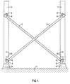
- Figure 1 shows a section of a side of a furnace insert with two support elements 1, which on a base plate 7 are permanently installed.
- the base plate 7 is suitable for inserting the furnace insert into the combustion chamber Kiln.
- the base plate 7, for example be provided with wheels so that the entire furnace insert can be run into the kiln.
- the columnar Support elements 1, which are suitably shaped for loading, Cross members, not shown here, are via a diagonal strut with the help of the two struts 3 stabilized against each other.
- the base 9 of the support elements 1 is downwards to increase the stability thickened.
- Support elements 1 each with holes 8 at their lower end each for holding a holder 5 at different heights Mistake.
- Each strut 3 is at both ends with With the help of the bracket 5 pivotable on the respective support element 1 attached.
- the bracket 5 is with the help of a Bolt 6 rotatably attached to the respective support element 1. Thermal expansion in the longitudinal direction of the strut 3 during the burning process is carried out by rotating the respective holder 5 balanced around the bolt 6.
- the support elements 1, the brackets 5 and the struts 3 each consist of one Silicon carbide material, and are therefore special temperature resistant.
- the pivotable fastening of a strut 3 in the holder 5 on a support element 1 is in perspective shown in Figure 2.
- the strut 3 is rectangular Molded with a hollow profile.
- the bracket 5 is U-shaped with a first leg 12 and a second Leg 13 and with a substantially flat contact surface 14 trained.
- the two legs 12, 13 of the bracket 5 each have an opening 16 at their upper end or 15 on, in which a bolt 6 is rotatably mounted. So that the holder 5 does not slip off the pin 6, points this one slightly thickened compared to the rest of the cross section Head 20 on.
- To attach the bracket 5 to the Support element 1 is the bolt 6 by a corresponding one Bore of the support element 1 (see Figure 1) inserted and on the side opposite the bracket 5 with the help of a Fuse 21 secured against slipping out.
- the inner side of the support surface 14 is with a wave-shaped structure 22 provided in the form of a sine wave.
- a wave-shaped structure 22 provided in the form of a sine wave.
- the one that comes into contact with the contact surface 14 Part of the strut 3 with a second undulating structure provided in the form of a sinus arch.
- Both wavy Structures 22, 23 are interlocked so that the strut 3 mechanically against a displacement relative to the contact surface 14 is secured.
- the gearing itself is done by Inserting a clamping wedge 24 between the bolt 6 and the Strut 3.
- Figure 3 shows the attachment in a cross section the strut 3 on the bracket 5. You can clearly see as with the help of the clamping wedge 24, the strut 3 on the support surface 14 is pressed and thereby the first wavy Structure 22 of the support surface 14 with the second undulating structure 23 of the strut 3 is toothed.
Landscapes
- Engineering & Computer Science (AREA)
- Mechanical Engineering (AREA)
- General Engineering & Computer Science (AREA)
- Furnace Charging Or Discharging (AREA)
- Muffle Furnaces And Rotary Kilns (AREA)
- Resistance Heating (AREA)
Abstract
Description
- FIG 1
- zwei durch eine Diagonalverstrebung stabilisierte Stützelemente als Ausschnitt eines Brennofeneinschubs;
- FIG 2
- in perspektivischer Darstellung eine vorteilhafte Ausgestaltung der mittels einer Halterung schwenkbaren Befestigung einer Strebe an einem Stützelement und
- FIG 3
- einen Schnitt durch die in FIG 2 gezeigte Halterung mit daran befestigter Strebe.
Claims (10)
- Brennofeneinschub aus temperaturbeständigem Material, insbesondere zum Brennen keramischer Formstücke, mit einer Anzahl von Stützelementen (1), welche mit einer Anzahl von stabilisierenden, sich jeweils im wesentlichen in einer Längsrichtung erstreckenden Streben (3) verbunden sind, wobei die oder jede Strebe (3) mittels einer Halterung (5) jeweils in Längsrichtung schwenkbar an einem Stützelement (1) befestigt ist, und wobei die oder jede Strebe (3) form- oder kraftschlüssig mit der jeweiligen Halterung (5) verbunden ist.
- Brennofeneinschub nach Anspruch 1, bei dem die oder jede Strebe (3) in jeweiliger Längsrichtung an verschiedener Position form- oder kraftschlüssig mit der jeweiligen Halterung (5) befestigbar ist.
- Brennofeneinschub nach Anspruch 1 oder 2, bei dem die Halterung (5) eine Auflagefläche (14) zur Aufnahme und zur Befestigung einer Strebe (3) und eine Öffnung (15,16) zur Aufnahme eines Bolzens (6) aufweist, mit dem sie an dem Stützelement (1) gelagert ist.
- Brennofeneinschub nach Anspruch 3, bei dem die Auflagefläche (14) mit einer ersten wellenförmigen Struktur (22) und zumindest der von der Auflagefläche (14) aufnehmbare Teil der oder jeder Strebe (3) mit einer zweiten wellenförmigen Struktur (23) versehen ist, und die erste wellenförmige Struktur (22) mit der zweiten wellenförmigen Struktur (23) verzahnt ist.
- Brennofenelnschub nach Anspruch 4, bei dem mittels eines Klemmkeils (24) die erste wellenförmige Struktur (22) mit der zweiten wellenförmigen Struktur (23) verzahnt ist.
- Brennofeneinschub nach einem der Ansprüche 1 bis 5, bei dem die Halterung (5) U-förmig ausgebildet ist, wobei die Auflagefläche (14) zwischen einem ersten Schenkel (12) der Halterung (5) und einem zweiten Schenkel (13) der Halterung (5) angeordnet ist.
- Brennofeneinschub nach Anspruch 6, bei dem die oder Jede Strebe (3) einen im wesentlichen rechteckigen Querschnitt aufweist und jeweils auf der Auflagefläche (14) befestigt ist.
- Brennofeneinschub nach Anspruch 7, bei dem jeder Schenkel (12, 13) der Halterung (5) am oberen Ende jeweils mit der Öffnung (15, 16) zur Aufnahme des Bolzens (6) versehen ist, der Bolzen (6) bei der Befestigung der U-förmigen Halterung (5) beide Schenkel (12, 13) der Halterung (5) überbrückt, die Auflagefläche (14) mit der ersten wellenförmigen Struktur (22) und die der Auflagefläche (14) zugewandte Seite der oder jeder Strebe (3) mit der zweiten wellenförmigen Struktur (23) versehen ist und der Klemmkeil (24) zur Verzahnung der ersten (22) und zweiten wellenförmigen Struktur (23) zwischen dem Bolzen (6) und der auf der Auflagefläche (14) aufliegenden Strebe (3) eingeklemmt ist.
- Brennofeneinschub nach einem der Ansprüche 1 bis 8, bei dem das temperaturbeständige Material ein Silizium-Karbid-Werkstoff ist.
- Brennofeneinschub nach einem der Ansprüche 1 bis 9, bei dem die oder jede Strebe (3) ein Hohlprofil aufweist.
Applications Claiming Priority (2)
| Application Number | Priority Date | Filing Date | Title |
|---|---|---|---|
| DE19713121A DE19713121C2 (de) | 1997-03-27 | 1997-03-27 | Brennofeneinschub |
| DE19713121 | 1997-03-27 |
Publications (3)
| Publication Number | Publication Date |
|---|---|
| EP0867676A2 true EP0867676A2 (de) | 1998-09-30 |
| EP0867676A3 EP0867676A3 (de) | 1999-04-07 |
| EP0867676B1 EP0867676B1 (de) | 2001-11-21 |
Family
ID=7824935
Family Applications (1)
| Application Number | Title | Priority Date | Filing Date |
|---|---|---|---|
| EP98104702A Expired - Lifetime EP0867676B1 (de) | 1997-03-27 | 1998-03-16 | Brennofeneinschub |
Country Status (3)
| Country | Link |
|---|---|
| EP (1) | EP0867676B1 (de) |
| AT (1) | ATE209328T1 (de) |
| DE (2) | DE19713121C2 (de) |
Citations (3)
| Publication number | Priority date | Publication date | Assignee | Title |
|---|---|---|---|---|
| DE3011114A1 (de) * | 1980-03-22 | 1981-10-01 | Rudolf 5000 Köln Klefisch | Korb aus hitzebestaendigem stahl zum brennen von tonwaren |
| DE4329468C1 (de) * | 1993-09-01 | 1995-02-09 | Carborundum Deutschland Gmbh | Traggestell für Ofenwagen zum Brennen feuerfester oder keramischer Gegenstände |
| DE4436140C1 (de) * | 1994-10-10 | 1995-11-16 | Riedhammer Gmbh Co Kg | Tragschiene und Aufbau für einen Brenntisch unter Verwendung der Tragschiene |
-
1997
- 1997-03-27 DE DE19713121A patent/DE19713121C2/de not_active Expired - Fee Related
-
1998
- 1998-03-16 DE DE59802189T patent/DE59802189D1/de not_active Expired - Fee Related
- 1998-03-16 AT AT98104702T patent/ATE209328T1/de not_active IP Right Cessation
- 1998-03-16 EP EP98104702A patent/EP0867676B1/de not_active Expired - Lifetime
Patent Citations (3)
| Publication number | Priority date | Publication date | Assignee | Title |
|---|---|---|---|---|
| DE3011114A1 (de) * | 1980-03-22 | 1981-10-01 | Rudolf 5000 Köln Klefisch | Korb aus hitzebestaendigem stahl zum brennen von tonwaren |
| DE4329468C1 (de) * | 1993-09-01 | 1995-02-09 | Carborundum Deutschland Gmbh | Traggestell für Ofenwagen zum Brennen feuerfester oder keramischer Gegenstände |
| DE4436140C1 (de) * | 1994-10-10 | 1995-11-16 | Riedhammer Gmbh Co Kg | Tragschiene und Aufbau für einen Brenntisch unter Verwendung der Tragschiene |
Also Published As
| Publication number | Publication date |
|---|---|
| EP0867676B1 (de) | 2001-11-21 |
| EP0867676A3 (de) | 1999-04-07 |
| DE59802189D1 (de) | 2002-01-03 |
| ATE209328T1 (de) | 2001-12-15 |
| DE19713121C2 (de) | 1999-04-08 |
| DE19713121A1 (de) | 1998-10-01 |
Similar Documents
| Publication | Publication Date | Title |
|---|---|---|
| DE2329888C3 (de) | Bewegliche Trennwand | |
| DE102007008527B4 (de) | Vergrößerbare Platte | |
| EP0867676B1 (de) | Brennofeneinschub | |
| EP0417177B1 (de) | Regalsystem | |
| DE1903685B1 (de) | Metallurgisches Kippgefaess,insbesondere Konverter zum Frischen von Roheisen | |
| DE8602265U1 (de) | Verbindungselement für Gestelle | |
| AT410126B (de) | Verstellmechanismus | |
| AT502878B1 (de) | Schieberegalanlage | |
| DE102014108514B4 (de) | Ofengestell zur Beschickung einer Ofenanlage mit einem Warmbehandlungsgut | |
| EP0607462B1 (de) | Doppelboden | |
| DE3331811A1 (de) | Geruestfeld, insbesondere fuer baustellen | |
| DE4436140C1 (de) | Tragschiene und Aufbau für einen Brenntisch unter Verwendung der Tragschiene | |
| DE102010032025B4 (de) | Unterbau eines Zeltes und Zelt mit einem solchen Unterbau | |
| DE8313165U1 (de) | Elastische Koksofentür mit Mehrfachverriegelung | |
| DE4317371C2 (de) | Vorrichtung zum Handhaben von Mauersteinen | |
| DE3929557C2 (de) | ||
| DE670269C (de) | Gehaenge fuer schwere Schiebetueren und -tore mit Tragkasten | |
| EP0898454B1 (de) | Traggestell | |
| EP4301948A1 (de) | Anschlussvorrichtung, deckenschalungssystem mit anschlussvorrichtung sowie verwendung einer anschlussvorrichtung | |
| DE4140011C1 (en) | Height-adjustable shelving structure - has support rod which jams in bore through each shelf unit | |
| DE19626854A1 (de) | Traggestell für einen höhenverstellbaren Tisch | |
| DE3344178A1 (de) | Industrieofen mit isolierung aus mineralfasermaterial | |
| DE3521706A1 (de) | Industrieofen | |
| WO1986004478A1 (en) | Electrically-heated industrial oven | |
| DE3127187A1 (de) | "regal, insbesondere fuer buechereien" |
Legal Events
| Date | Code | Title | Description |
|---|---|---|---|
| PUAI | Public reference made under article 153(3) epc to a published international application that has entered the european phase |
Free format text: ORIGINAL CODE: 0009012 |
|
| AK | Designated contracting states |
Kind code of ref document: A2 Designated state(s): AT DE FR SE |
|
| AX | Request for extension of the european patent |
Free format text: AL;LT;LV;MK;RO;SI |
|
| PUAL | Search report despatched |
Free format text: ORIGINAL CODE: 0009013 |
|
| AK | Designated contracting states |
Kind code of ref document: A3 Designated state(s): AT BE CH DE DK ES FI FR GB GR IE IT LI LU MC NL PT SE |
|
| AX | Request for extension of the european patent |
Free format text: AL;LT;LV;MK;RO;SI |
|
| 17P | Request for examination filed |
Effective date: 19990505 |
|
| AKX | Designation fees paid |
Free format text: AT DE FR SE |
|
| GRAG | Despatch of communication of intention to grant |
Free format text: ORIGINAL CODE: EPIDOS AGRA |
|
| GRAG | Despatch of communication of intention to grant |
Free format text: ORIGINAL CODE: EPIDOS AGRA |
|
| GRAH | Despatch of communication of intention to grant a patent |
Free format text: ORIGINAL CODE: EPIDOS IGRA |
|
| 17Q | First examination report despatched |
Effective date: 20010508 |
|
| GRAH | Despatch of communication of intention to grant a patent |
Free format text: ORIGINAL CODE: EPIDOS IGRA |
|
| GRAA | (expected) grant |
Free format text: ORIGINAL CODE: 0009210 |
|
| AK | Designated contracting states |
Kind code of ref document: B1 Designated state(s): AT DE FR SE |
|
| REF | Corresponds to: |
Ref document number: 209328 Country of ref document: AT Date of ref document: 20011215 Kind code of ref document: T |
|
| REF | Corresponds to: |
Ref document number: 59802189 Country of ref document: DE Date of ref document: 20020103 |
|
| ET | Fr: translation filed | ||
| PLBE | No opposition filed within time limit |
Free format text: ORIGINAL CODE: 0009261 |
|
| STAA | Information on the status of an ep patent application or granted ep patent |
Free format text: STATUS: NO OPPOSITION FILED WITHIN TIME LIMIT |
|
| 26N | No opposition filed | ||
| PGFP | Annual fee paid to national office [announced via postgrant information from national office to epo] |
Ref country code: AT Payment date: 20030212 Year of fee payment: 6 |
|
| PGFP | Annual fee paid to national office [announced via postgrant information from national office to epo] |
Ref country code: FR Payment date: 20030318 Year of fee payment: 6 |
|
| PGFP | Annual fee paid to national office [announced via postgrant information from national office to epo] |
Ref country code: SE Payment date: 20030324 Year of fee payment: 6 |
|
| PGFP | Annual fee paid to national office [announced via postgrant information from national office to epo] |
Ref country code: DE Payment date: 20030328 Year of fee payment: 6 |
|
| PG25 | Lapsed in a contracting state [announced via postgrant information from national office to epo] |
Ref country code: AT Free format text: LAPSE BECAUSE OF NON-PAYMENT OF DUE FEES Effective date: 20040316 |
|
| PG25 | Lapsed in a contracting state [announced via postgrant information from national office to epo] |
Ref country code: SE Free format text: LAPSE BECAUSE OF NON-PAYMENT OF DUE FEES Effective date: 20040317 |
|
| PG25 | Lapsed in a contracting state [announced via postgrant information from national office to epo] |
Ref country code: DE Free format text: LAPSE BECAUSE OF NON-PAYMENT OF DUE FEES Effective date: 20041001 |
|
| EUG | Se: european patent has lapsed | ||
| PG25 | Lapsed in a contracting state [announced via postgrant information from national office to epo] |
Ref country code: FR Free format text: LAPSE BECAUSE OF NON-PAYMENT OF DUE FEES Effective date: 20041130 |
|
| REG | Reference to a national code |
Ref country code: FR Ref legal event code: ST |