EP0867275A1 - Punch press with tooling - Google Patents
Punch press with tooling Download PDFInfo
- Publication number
- EP0867275A1 EP0867275A1 EP97105079A EP97105079A EP0867275A1 EP 0867275 A1 EP0867275 A1 EP 0867275A1 EP 97105079 A EP97105079 A EP 97105079A EP 97105079 A EP97105079 A EP 97105079A EP 0867275 A1 EP0867275 A1 EP 0867275A1
- Authority
- EP
- European Patent Office
- Prior art keywords
- tool
- tool unit
- unit
- ram
- upper tool
- Prior art date
- Legal status (The legal status is an assumption and is not a legal conclusion. Google has not performed a legal analysis and makes no representation as to the accuracy of the status listed.)
- Granted
Links
Images


Classifications
-
- B—PERFORMING OPERATIONS; TRANSPORTING
- B30—PRESSES
- B30B—PRESSES IN GENERAL
- B30B15/00—Details of, or accessories for, presses; Auxiliary measures in connection with pressing
- B30B15/04—Frames; Guides
- B30B15/041—Guides
-
- B—PERFORMING OPERATIONS; TRANSPORTING
- B30—PRESSES
- B30B—PRESSES IN GENERAL
- B30B15/00—Details of, or accessories for, presses; Auxiliary measures in connection with pressing
- B30B15/02—Dies; Inserts therefor; Mounting thereof; Moulds
- B30B15/026—Mounting of dies, platens or press rams
Definitions
- the present invention relates to a Punch press with at least one tool device, which punch press has at least one ram and one machine frame has, and which plunger by means Ram guides in the machine frame, which Tool device an upper tool unit, a lower tool unit and an arrangement of guide devices has, by means of which the upper tool unit for a movement in the stroke direction of the ram is guided in the lower tool unit.
- Each module forms one complete tool with a tool head and a tool base and guides some, but not all processing steps on the belt to be processed by. That means that in the punch press several in Direction of passage of the strip to be processed in succession Arranged modules are built in with respect on the entire processing process together form a long follow-up tool.
- the upper part of the tool which is in operation of the punch press moved, relative to the lower tool part by column guides performed, the upper part of the tool is in operation moving guide links in the form of guide columns has, which in as fixed guide members acting column guides in the lower part of the tool are, i.e. the pillars are at leadership positions in guided the column guides, and there usually four Guide columns and column guides are present, determine the management positions together the management level of the module.
- the advantage of the modular design is general in the rational production of the tools, in the interchangeability (e.g. for regrinding some worn ones Tool parts), and easier handling.
- the upper frame part has guide columns as moving links in the company on and the lower frame part has column guides as fixed links in the company.
- another management level namely determine the management level of the mother rack.
- Im in the Punch press installed condition is the upper part of the frame the mother frame with the ram of the punch press and the lower part of the frame is connected to the platen, which the latter with the machine frame of the punch press is firmly connected.
- the tappet is equipped with guide columns, which are guided in column guides in the machine frame are.
- the punch press is also a leader (in the column guides) that together yet another, i.e. determine third management level.
- the first management level is through module tours between the module tool upper part and the module tool lower part certainly.
- the second management level is through the mother frame guides between the upper frame part and the lower frame part of the mother frame certainly.
- the third management level is through the ram guides between the ram and the machine frame the punch press.
- the invention seeks to remedy this.
- the Invention as characterized in the claims solves the task of a punch press with a tool device to create a minimal number of bearings needed for guidance in the direction of the stroke and by means of which different thermal expansions practically lossless can be picked up by the upper tool unit the tool device by means of connecting units directly with a section of the punch of the punch press is connected, which is only transverse to the stroke direction running displacement between the upper tool unit and allow the pestle.
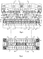
- FIG. 1 shows the ram 1 of a punch press, which is articulated in a known manner on pressure columns 2 is, which in turn articulated on one-armed levers 3 are.
- One end of the one-armed lever 3 is at one Connecting rod 4 articulated in a known manner on a Eccentric shaft or crankshaft (not shown) is.
- the one-armed levers 3 hinged to devices 5 for ram height adjustment.
- the rotary movement of the eccentric or Crankshaft through the connecting rod into a translatory Movement implemented by means of the one arm Lever 3 is transferred to the plunger 1.
- This arrangement and working method including ram height adjustment is generally known and therefore does not have to are described in more detail.
- the ram is connected to guide columns 6, which are guided in column guides 7.
- This from the Guide columns 6 and column guides 7 existing guide arrangement and their operation is in CH-A-568 848 and US-A-3 998 498, respectively, and it hereby expressly states the disclosure of these documents pointed out.
- the specific arrangement of the column guides 7 and in particular the course of their sliding surfaces can be seen from Figure 2.
- the through the Guide pillars 6 and pillar guides 7 certain management level coincides with the tape running level, which through the two outer sections of section line II-II is shown in Fig. 1.
- the column guides 7 are with connected to the machine frame 8. On the machine frame 8, a platen 9 is screwed on. Continue is an alignment plate 10 screwed to the platen 9.
- the plunger shown in the drawing figures 1 has a lower section 11 which is plate-shaped trained and rigid with the remaining plunger 1 connected is. However, it should be clearly stated that the entire plunger 1, 11 is formed in one piece can be, so that the parts 1, 11 an undivided Form workpiece.
- the drive is from the connecting rod 4 over the one-armed lever 3, 3 '.
- These double levers 31, 32, 33, 34 act on the pressure columns 35, 36, 37, 38 Tappets 13, 11 and 14, 11 '.
- the plungers 13, 11 and 14, 11 ' are listed in three places, the two in the figures 3 and 4 outermost guides equal to that in the figure 1 and 2 guides are formed.
- the plungers 13. 11 and 14, 11 ' can move from the points O, O 'towards the Extend arrows k, l, m and n, o, p freely, with that of most distant modules 12 am most severely affected by the occurring changes in length are and in particular they can freely expand in the direction of arrows m and n.
- the module 12 i.e. the tool device, has an upper tool unit 17.
- This upper tool unit 17 is located directly at the bottom of the Tappet 1, 11, with the drawn version the ram section 11 as one with the rest of the ram 1 screwed plate is shown, which two-part Ram design is not mandatory.
- the Plate 11 could just as well be a one-piece section of the entire ram.
- the lower tool unit 20 is still in one to be described by means of bolts 21, 22 with an alignment plate 10 screwed, which in turn by means of bolts 23, 24 with the clamping plate 9 is screwed.
- the module 12 shown is one, for example Execution of a tool and it is for the Specialist obviously that there are tools for Stamping presses are very different designs, each after the processing to be carried out on the line.
- Tool device i.e. Tool device has a stamp holding and pressure plate as the upper tool unit 17 25 in which a stamp 26 is inserted, and has a guide or stripping plate 27.
- the lower tool 20 has a cutting and Pressure plate 28 on.
- the guide plate 27 is also by means of Linear ball bearing 45 on the guide columns 35, 36, 37, 38 guided.
- the stamp 26, which with the stamp holder 25th connected extends through this guide plate 27.
- the guide plate 27 is screwed into it Bolt 43 carried in the stamp holding plate 25 and through Compression springs 44 clamped away from the same.
- the reference number 47 denotes the sheet metal strip to be processed.
- each module 12 with the in the lower tool unit 20 used upper tool unit 19 placed on the alignment plate 10 and rough alignment in the direction of arrow R against the Stops 48, 49 pushed and thus roughly aligned.
- Precise bores are in the alignment plate 10 50 and in the pressure plate 28 are precise positioning holes 51 trained. After the module 12 by means of the stops 48, 49 have been roughly aligned, the positioning holes 50, 51 with each other exactly aligned and precisely machined positioning sleeves 52 through the positioning holes 51 into the positioning holes 50 inserted so that the lower tool unit 20 arranged exactly on the alignment plate 10 and is therefore aligned with the upper tool unit 17 is. Then the attachment takes place using the Bolts 21, 22, however, only as connecting elements between the lower tool unit 20 and the alignment plate 10 and not as side guide elements to serve.
- the upper stamp holding plate 25 is by means of screw 58 with the plate 11, that is, directly with a section of the ram of the punch press, connected, which are surrounded by bushes 54.
- holes 55 are formed in the stamp holding plate 25.
- auxiliary rifles (not shown) used, whose outside diameter is the inside diameter corresponds to the holes 55. So that the pestle is relative aligned to the upper tool unit 17 and centered.
- the bolts 58 are loosened again and the auxiliary rifles used for alignment replaced by bushes 54, the outer diameter of which is smaller than the inside diameter of the bores 55, so that a game S allowing horizontal displacement is available.
- the length of the sleeves 54 is on the thickness of the flange 56 adjusted so that after tightening the bolt 53 with a fixed Torque between the thrust washer 57 and the flange 56 there is a minimal game.
- the alignment plate 10 consist of several parts, each "Plate section” 11 and each "alignment plate section” 10 carries part of the total modules 12.
Abstract
Description
Die vorliegende Erfindung betrifft eine Stanzpresse mit mindestens einer Werkzeugvorrichtung, welche Stanzpresse mindestens einen Stössel und ein Maschinengestell aufweist, und welcher Stössel mittels Stösselführungen im Maschinengestell geführt ist, welche Werkzeugvorrichtung eine Oberwerkzeugeinheit, eine Unterwerkzeugeinheit und eine Anordnung von Führungseinrichtungen aufweist, mittels welchen die Oberwerkzeugeinheit für eine in Hubrichtung des Stössels gerichtete Bewegung in der Unterwerkzeugeinheit geführt ist.The present invention relates to a Punch press with at least one tool device, which punch press has at least one ram and one machine frame has, and which plunger by means Ram guides in the machine frame, which Tool device an upper tool unit, a lower tool unit and an arrangement of guide devices has, by means of which the upper tool unit for a movement in the stroke direction of the ram is guided in the lower tool unit.
Bei der modernen Stanztechnik geht die Entwicklung in Richtung einer vollständigen Verarbeitung eines Rohmaterials, also ein vollständiges spanloses Fertigen eines Erzeugnisses. Das heisst, dass eine Stanzpresse mit dem dazugehörigen Werkzeug zu einem vollständigen Fertigungszentrum ausgebildet wird. Nebst den üblichen Schneide- und Umform(Biege)-Operationen werden in Stanzpressen vermehrt auch Montage- und Fügearbeiten ausgeführt, es wird geschweisst, genietet und es werden auch Gewinde geformt. Entsprechend hergestellte Produkte bzw. Stanzteile weisen eine grosse Formvielfalt auf und benötigen folglich immer mehr Bearbeitungsfolgen, d.h. Bearbeitungsschritte. Dieses erfordert immer längere Werkzeuge und somit Stanzpressen mit immer längeren Werkzeugeinbauräumen. Lange Werkzeuge können zu verschiedenen Nachteilen führen. Beispielsweise wird die Herstellungsgenauigkeit beeinträchtigt und Wärmedehnungen können zu erheblichen Schwierigkeiten führen, die bezüglich der Ausbildung solcher langer Werkzeuge, deren Montage in den Stanzpressen und dem Erreichen von hochpräzisen Erzeugnissen äusserst schwer, wenn überhaupt, beherrscht werden können.The development goes with modern punching technology towards complete processing of a raw material, i.e. a complete chipless production of an article. That means that a punch press with the associated tool to a complete Manufacturing center is trained. In addition to the usual Cutting and forming (bending) operations are carried out in Punching presses also increasingly carried out assembly and joining work, it is welded, riveted and it is also Shaped thread. Products or Stamped parts have a large variety of shapes and require consequently more and more processing sequences, i.e. Processing steps. This requires longer and longer tools and thus punch presses with ever longer tool installation spaces. Long tools can have various disadvantages to lead. For example, the manufacturing accuracy impaired and thermal expansion can be significant Difficulties arise regarding training such long tools, their assembly in the Stamping presses and the achievement of high-precision products extremely difficult, if at all, to be mastered can.
Aus diesen Gründen hat sich beim Werkzeugbau die Modulbauweise durchgesetzt. Jedes Modul bildet ein vollständiges Werkzeug mit einem Werkzeugoberteil und einem Werkzeugunterteil und führt einige, jedoch nicht alle Bearbeitungsschritte auf dem zu verarbeitenden Band durch. Das heisst, dass in der Stanzpresse mehrere in Durchlaufrichtung des zu verarbeitenden Bandes aufeinanderfolgend angeordnete Module eingebaut sind, die in bezug auf den gesamten Verarbeitungsprozess zusammen ein langes Folgewerkzeug bilden. In jedem einzelnen Modul ist das Werkzeugoberteil, das sich im Betrieb der Stanzpresse bewegt, relativ zum unteren Werkzeugteil durch Säulenführungen geführt, wobei das Werkzeugoberteil sich im Betrieb bewegende Führungsglieder in Form von Führungssäulen aufweist, die in als feststehende Führungsglieder wirkende Säulenführungen im Werkzeugunterteil geführt sind, d.h. die Führungssäulen sind bei Führungsstellen in den Säulenführungen geführt, und da in der Regel vier Führungssäulen und Säulenführungen vorhanden sind, bestimmen die Führungsstellen zusammen die Führungsebene des Moduls.For these reasons, tool making the modular design prevailed. Each module forms one complete tool with a tool head and a tool base and guides some, but not all processing steps on the belt to be processed by. That means that in the punch press several in Direction of passage of the strip to be processed in succession Arranged modules are built in with respect on the entire processing process together form a long follow-up tool. In every single module is the upper part of the tool, which is in operation of the punch press moved, relative to the lower tool part by column guides performed, the upper part of the tool is in operation moving guide links in the form of guide columns has, which in as fixed guide members acting column guides in the lower part of the tool are, i.e. the pillars are at leadership positions in guided the column guides, and there usually four Guide columns and column guides are present, determine the management positions together the management level of the module.
Der Vorteil der Modulbauweise liegt allgemein in der rationellen Fertigung der Werkzeuge, in der Austauschbarkeit (z.B. zum Nachschleifen einiger abgenützter Werkzeugteile), und einer leichteren Handhabung.The advantage of the modular design is general in the rational production of the tools, in the interchangeability (e.g. for regrinding some worn ones Tool parts), and easier handling.
Gemäss bekannten Ausführungen sind die einzelnen Module in einem Muttergestell mit einem oberen Gestellteil und einem unteren Gestellteil angeordnet, welches Muttergestell wiederum eigene zwischen dem oberen Gestellteil und dem unteren Gestellteil wirkende Säulenführungen aufweist.According to known designs, the individual Modules in a mother frame with an upper frame part and a lower frame part arranged, which Mother rack in turn own between the top Frame part and the lower frame part acting column guides having.
Das heisst, der obere Gestellteil weist Führungssäulen als sich im Betrieb bewegende Führungsglieder auf und der untere Gestellteil weist Säulenführungen als im Betrieb feststehende Führungsglieder auf. Damit sind auch beim Muttergestell Führungsstellen vorhanden, die ihrerseits zusammen eine weitere Führungsebene, nämlich die Führungsebene des Muttergestells bestimmen. Im in der Stanzpresse eingebauten Zustand ist der obere Gestellteil des Muttergestells mit dem Stössel der Stanzpresse und der untere Gestellteil mit der Aufspannplatte verbunden, welch letztere mit dem Maschinenrahmen der Stanzpresse fest verbunden ist. Wenn äusserst präzise Stanzteile hergestellt werden, wozu der Schneidspalt, d.h. der Abstand zwischen dem Aussenumfang eines Stempels und dem Innenumfang der dazugehörigen Matrize sehr klein ist, wird der Werkzeugoberteil des betreffenden Moduls oft im oberen Gestellteil des Muttergestells horizontal verschiebbar gelagert.This means that the upper frame part has guide columns as moving links in the company on and the lower frame part has column guides as fixed links in the company. With that there are also guide points on the mother rack in turn, another management level, namely determine the management level of the mother rack. Im in the Punch press installed condition is the upper part of the frame the mother frame with the ram of the punch press and the lower part of the frame is connected to the platen, which the latter with the machine frame of the punch press is firmly connected. When extremely precise stamped parts are produced what the cutting gap, i.e. the distance between the outer circumference of a stamp and the inner circumference the corresponding die is very small, the Tool upper part of the module in question often in the upper one Frame part of the mother frame can be moved horizontally stored.
Der im Betrieb der Stanzmaschine Hubbewegungen durchführende Stössel ist mit Führungssäulen ausgerüstet, die in Säulenführungen im Maschinenrahmen geführt sind. Somit sind auch bei der Stanzpresse ebenfalls Führungsstellen (in den Säulenführungen) vorhanden, die zusammen eine noch weitere, d.h. dritte Führungsebene bestimmen.The lifting movements during the operation of the punching machine the tappet is equipped with guide columns, which are guided in column guides in the machine frame are. This means that the punch press is also a leader (in the column guides) that together yet another, i.e. determine third management level.
Damit sind bei Stanzpressen mit mehrere Module aufweisenden Werkzeugen also drei Führungsebenen vorhanden. Die erste Führungsebene ist durch Modulführungen zwischen dem Modul-Werkzeugoberteil und dem Modul-Werkzeugunterteil bestimmt. Die zweite Führungsebene ist durch die Muttergestellführungen zwischen dem oberen Gestellteil und dem unteren Gestellteil des Muttergestells bestimmt. Die dritte Führungsebene ist durch die Stösselführungen zwischen dem Stössel und dem Maschinenrahmen der Stanzpresse bestimmt.This means that punching presses have several modules tools have three management levels. The first management level is through module tours between the module tool upper part and the module tool lower part certainly. The second management level is through the mother frame guides between the upper frame part and the lower frame part of the mother frame certainly. The third management level is through the ram guides between the ram and the machine frame the punch press.
Moderne Stanzpressen arbeiten mit hohen Hubzahlen. Diese Tatsache führt zu höheren Reibungsverlusten und folglich einer Erhöhung der insgesamten Maschinentemperatur. Es wird wohl angestrebt, eine gleichmässige Erwärmung der einzelnen Bauteile der Stanzpressen zu erreichen und bekanntlich werden hierzu Heiz- und Kühlgeräte verwendet. Es ist jedoch nicht zu vermeiden, dass sich nach dem Anfahren der Stanzpresse beim Erreichen der Betriebstemperatur zwischen dem Pressenstössel und dem Maschinenrahmen eine Temperaturdifferenz einstellt. Die folglich vorhandenen unterschiedlichen Wärmedehnungen führen zu einem äusserst unerwünschten Zustand der Verspannung zwischen den einzelnen oben beschriebenen Führungen und zu einer unerwünschten Verlagerung zwischen z.B. einem Stempel und der dazugehörigen Matrize der Werkzeuge. Verspannte Führungen ergeben höhere Reibungsverluste, erhöhten Energiebedarf, schnellere Abnützung der betreffenden Bauteile und bei kleinen Schneidspalten für Präzisionsteile einen erhöhten Werkzeugverschleiss.Modern punch presses work with high stroke rates. This fact leads to higher friction losses and consequently an increase in the overall machine temperature. The aim is to achieve uniform warming of the individual components of the punch presses and it is known that heating and cooling devices are used for this purpose used. However, it is inevitable that after starting the punch press when the operating temperature is reached between the press ram and the machine frame sets a temperature difference. The consequently different thermal expansions present lead to an extremely undesirable state of tension between the individual tours described above and an unwanted shift between e.g. a stamp and the corresponding die of Tools. Tensioned guides result in higher friction losses, increased energy requirements, faster wear of the relevant components and with small cutting gaps increased tool wear for precision parts.
Hier will die Erfindung Abhilfe schaffen. Die Erfindung, wie sie in den Ansprüchen gekennzeichnet ist, löst die Aufgabe, eine Stanzpresse mit einer Werkzeugvorrichtung zu schaffen, die eine minimale Anzahl Lagerstellen zur Führung in Hübrichtung benötigt und mittels welcher unterschiedliche Wärmedehnungen praktisch verlustlos aufgenommen werden können, indem die Oberwerkzeugeinheit der Werkzeugvorrichtung mittels Verbindungseinheiten unmittelbar mit einem Abschnitt des Stössels der Stanzpresse verbunden ist, die ausschliesslich eine quer zur Hubrichtung verlaufende Verschiebung zwischen der Oberwerkzeugeinheit und dem Stössel erlauben.The invention seeks to remedy this. The Invention as characterized in the claims solves the task of a punch press with a tool device to create a minimal number of bearings needed for guidance in the direction of the stroke and by means of which different thermal expansions practically lossless can be picked up by the upper tool unit the tool device by means of connecting units directly with a section of the punch of the punch press is connected, which is only transverse to the stroke direction running displacement between the upper tool unit and allow the pestle.
Die durch die Erfindung erreichten Vorteile sind im wesentlichen darin zu sehen, dass die Werkzeugvorrichtung in nur noch einer Ebene geführt wird und dass damit Verspannungen und Reibverluste bei den Führungen beträchtlich vermindert werden. Bei der Stanzpresse mit den eingebauten Werkzeugvorrichtungen sind dieselben direkt mit einem Abschnitt des Stössels verbunden, so dass unterschiedliche Wärmedehnungen zwischen dem Stössel und dem Maschinenrahmen und auch Verspannungen und Reibverluste beträchtlich vermindert sind. Weiter ist die sich bewegende Masse der Werkzeugvorrichtung und der Stanzpresse verkleinert.The advantages achieved by the invention are essentially to be seen in the fact that the tool device is managed in just one level and that thus tension and friction losses in the guides be considerably reduced. With the punch press with the built-in tool fixtures are the same connected to a portion of the ram so that different thermal expansions between the ram and the machine frame and also tension and friction losses are considerably reduced. Next is the moving one Mass of the tool device and the punch press downsized.
Im folgenden wird die Erfindung anhand von
lediglich einen Ausführungsweg darstellenden Zeichnungen
näher erläutert.
Figur 1 zeigt den Stössel 1 einer Stanzpresse,
der in bekannter Weise an Drucksäulen 2 angelenkt
ist, welche ihrerseits an einarmigen Hebeln 3 angelenkt
sind. Das eine Ende der einarmigen Hebel 3 ist an einem
Pleuel 4 angelenkt, der in bekannter Weise auf einer
(nicht gezeigten) Exzenterwelle oder Kurbelwelle gelagert
ist. Beim entgegengesetzten Ende sind die einarmigen Hebel
3 an Vorrichtungen 5 zur Stösselhöhenverstellung angelenkt.
Im Betrieb wird die Drehbewegung der Exzenter- oder
Kurbelwelle durch die Pleuelstange in eine translatorische
Bewegung umgesetzt, die mittels der einarmigen
Hebel 3 auf den Stössel 1 übertragen wird. Diese Anordnung
und Arbeitsweise einschliesslich der Stösselhöhenverstellung
ist allgemein bekannt und muss somit nicht
näher beschrieben werden.FIG. 1 shows the
Der Stössel ist mit Führungssäulen 6 verbunden,
die in Säulenführungen 7 geführt sind. Diese aus den
Führungssäulen 6 und Säulenführungen 7 bestehende Führungsanordnung
und deren Arbeitsweise ist in der CH-A-568
848 bzw. US-A-3 998 498 im Einzelnen beschrieben und es
wird hiermit ausdrücklich auf die Offenbarung dieser Dokumente
hingewiesen. Die spezifische Anordnung der Säulenführungen
7 und insbesondere der Verlauf deren Gleitflächen
ist aus der Figur 2 ersichtlich. Die durch die
Führungssäulen 6 und Säulenführungen 7 bestimmte Führungsebene
fällt mit der Bandlaufebene zusammen, welche
durch die zwei äusseren Abschnitte der Schnittlinie II-II
in Fig. 1 aufgezeigt ist. Die Säulenführungen 7 sind mit
dem Maschinengestell 8 verbunden. Auf dem Maschinengestell
8 ist eine Aufspannplatte 9 aufgeschraubt. Weiter
ist eine Ausrichtplatte 10 mit der Aufspannplatte 9 verschraubt.
Der in den Zeichnungsfiguren dargestellte Stössel
1 weist einen unteren Abschnitt 11 auf, der plattenförmig
ausgebildet und starr mit dem restlichen Stössel 1
verbunden ist. Es soll jedoch deutlich festgehalten werden,
dass der gesamte Stössel 1, 11 einstückig ausgebildet
sein kann, so dass die Teile 1, 11 ein ungetrenntes
Werkstück bilden.The ram is connected to
Nachfolgend werden nun die Wärmedehnungen während dem Betrieb der Stanzpresse erläutert.Below are the thermal expansions explained during the operation of the punch press.
Beim Punkt O (Fig. 1) wird die Wärmedehnung
grundsätzlich in Richtung der Pfeile a und b erfolgen
(und auch umgekehrt). Offensichtlich sind die Module 12,
die die grösste Entfernung von Punkt O aufweisen von der
Längenveränderung des Stössels 1, mit dem sie verbunden
sind, von der Längenveränderung am meisten betroffen.At point O (Fig. 1) the thermal expansion
always take place in the direction of arrows a and b
(and vice versa). Obviously,
Bei Betrachtung der Figur 2 wird es ersichtlich, dass aufgrund der Stösselführungen die Wärmeausdehnung von den Punkten c und d aus nur in Richtung der Pfeile e, f, g und h, i, j erfolgen kann (siehe die bereits genannten CH-A-568 848 oder US-A-3 998 498), wobei in Richtung der Pfeile g und j, insbesondere bei längeren Stösseln, beträchtliche Druckspannungen entstehen, was zu Verspannungen in den Führungen des Stössels führt.When viewing FIG. 2, it becomes clear that that due to the ram guides the thermal expansion from points c and d only in the direction of Arrows e, f, g and h, i, j can be done (see the already CH-A-568 848 or US-A-3 998 498), wherein in the direction of arrows g and j, especially for longer ones Tappets, considerable compressive stresses arise, causing Tension in the ram guides.
Eine Stanzpresse mit einem sehr langen Werkzeugeinbauraum
ist in den Figuren 3 und 4 dargestellt.
Diese Stanzpresse ist in der EP-A-724 953 ausführlich offenbart
und es wird aus Gründen der Offenbarung ausdrücklich
auf diese EP-A-724 953 hingewiesen. Für die hier zu
machenden Ueberlegungen ist lediglich zu bemerken, dass
in Banddurchlaufrichtung zwei aufeinanderfolgende Stössel
13 und 14 vorhanden sind.A punch press with a very long tool installation space
is shown in Figures 3 and 4.
This punch press is disclosed in detail in EP-A-724 953
and it becomes explicit for the sake of revelation
referred to this EP-A-724 953. For those here too
The only considerations to be made are that
Two successive plungers in the direction of
Der Antrieb erfolgt vom Pleuel 4 her über die
einarmigen Hebel 3, 3'. An den einarmigen Hebeln sind Laschen
29, 30 angelenkt, die ihrerseits an Doppelhebeln
31, 32, 33, 34 angelenkt sind. Diese Doppelhebel 31, 32,
33, 34 wirken über Drucksäulen 35, 36, 37, 38 auf die
Stössel 13,11, und 14,11'. Die Stössel 13, 11 und 14, 11'
sind an drei Stellen geführt, wobei die zwei in den Figuren
3 und 4 äussersten Führungen gleich der in der Figur
1 und 2 gezeigten Führungen ausgebildet sind.The drive is from the connecting rod 4 over the
one-
Es wird jedoch auf die Stösselführungen 15
und 16 aufmerksam gemacht. Die Stössel 13. 11 und 14, 11'
können sich von den Punkten O, O' aus in Richtung der
Pfeile k, l, m und n, o, p frei ausdehnen, wobei die von
den Punkten O, O' am weitesten entfernten Module 12 am
stärksten von den auftretenden Längenveränderungen betroffen
sind und insbesondere können sie sich ungehindert
in Richtung der Pfeile m und n ausdehnen.However, it is on the slide guides 15th
and 16 alerted. The
Unter Bezugnahme auf die Figuren 5 und 6 wird nun eine bevorzugte Ausführung einer Werkzeugvorrichtung gemäss der Erfindung beschrieben, die den genannten Nachteilen entgegenwirkt und als eines der Module ausgebildet ist.Referring to Figures 5 and 6 now a preferred embodiment of a tool device described according to the invention, the disadvantages mentioned counteracts and trained as one of the modules is.
Das Modul 12, also die Werkzeugvorrichtung,
weist eine Oberwerkzeugeinheit 17 auf. Diese Oberwerkzeugeinheit
17 liegt direkt an der Unterseite des
Stössels 1, 11 an, wobei bei der gezeichneten Ausführung
der Stösselabschnitt 11 als eine mit dem restlichen Stössel
1 verschraubte Platte dargestellt ist, welche zweiteilige
Stösselausführung jedoch nicht zwingend ist. Die
Platte 11 könnte geradesogut ein einteiliger Abschnitt
des gesamten Stössels sein.The
Die Unterwerkzeugeinheit 20 ist in einer noch
zu beschreibenden Weise mittels Schraubbolzen 21, 22 mit
einer Ausrichtplatte 10 fest verschraubt, die ihrerseits
mittels Schraubbolzen 23, 24 mit der Aufspannplatte 9
verschraubt ist.The
Das dargestellte Modul 12 ist eine beispielsweise
Ausführung eines Werkzeuges und es ist für den
Fachmann offensichtlich, dass es bei Werkzeugen für
Stanzpressen sehr unterschiedliche Ausführungen gibt, je
nach den am Band durchzuführenden Bearbeitungen.The
Das Modul 12, d.h. Werkzeugvorrichtung weist
als Oberwerkzeugeinheit 17 eine Stempelhalte- und Druckplatte
25 auf, in welcher ein Stempel 26 eingesetzt ist,
und weist eine Führungs- bzw. Abstreifplatte 27 auf.
Das Unterwerkzeug 20 weist eine Schnitt- und
Druckplatte 28 auf.The
In die Platte 25 sind vier Führungssäulen 35,
36, 37, 38 eingepresst. Diese Führungssäulen 35, 36, 37,
38 sind in spielfreien Säulenführungen 39, 40, 41, 42 im
Unterwerkzeug 20 geführt. Diese Säulenführungen sind als
Linearkugellager ausgebildet.In the
Die Führungsplatte 27 ist ebenfalls mittels
Linearkugellager 45 an den Führungssäulen 35, 36, 37, 38
geführt. Der Stempel 26, der mit dem Stempelhalter 25
verbunden ist, erstreckt sich durch diese Führungsplatte
27. Die Führungsplatte 27 ist über in sie eingeschraubte
Bolzen 43 in der Stempelhalteplatte 25 getragen und durch
Druckfedern 44 von derselben weggespannt. Durch die Führungen
39-42 und 45 ergibt sich eine optimale Schneidspaltverteilung
zwischen dem Stempel 26 und der Matrize
46 im Unterwerkzeug 20. Die Bezugsziffer 47 bezeichnet
das zu verarbeitende Blechband.The
Zum Zusammenbauen wird jedes Modul 12 mit der
in der Unterwerkzeugeinheit 20 eingesetzen Oberwerkzeugeinheit
19 auf die Ausrichtplatte 10 gestellt und zur
groben Ausrichtung in Richtung des Pfeiles R gegen die
Anschläge 48, 49 geschoben und damit grob ausgerichtet.To assemble each
In der Ausrichtplatte 10 sind präzise Bohrungen
50 und in der Druckplatte 28 sind präzise Positionierbohrungen
51 ausgebildet. Nachdem das Modul 12 mittels
der Anschläge 48, 49 grob ausgerichtet worden ist,
werden die Positionierbohrungen 50, 51 miteinander genau
ausgerichtet und präzise gearbeitete Positionierbüchsen
52 durch die Positionierbohrungen 51 hindurch in die Positionierbohrungen
50 gesteckt, so dass die Unterwerkzeugeinheit
20 genau auf der Ausrichtplatte 10 angeordnet
ist und folglich mit der Oberwerkzeugeinheit 17 ausgerichtet
ist. Danach erfolgt das Befestigen mittels der
Schraubbolzen 21, 22, die jedoch nur als Verbindungselemente
zwischen der Unterwerkzeugeinheit 20 und der Ausrichtplatte
10 und nicht als seitliche Führungselemente
dienen.Precise bores are in the
Die obere Stempelhalte- bzw. Druckplatte 25
ist mittels Schraubbolzen 58 mit der Platte 11, also direkt
mit einem Abschnitt des Stössels der Stanzpresse,
verbunden, die von Büchsen 54 umgeben sind. In der Stempelhalteplatte
25 sind Bohrungen 55 ausgebildet. Zum
erstweiligen Ausrichten der Platte 11 bezüglich der Stempelhalteplatte
25 werden (nicht gezeichnete) Hilfsbüchsen
verwendet, deren Aussendurchmesser dem Innendurchmesser
der Bohrungen 55 entspricht. Damit der Stössel relativ
zur Oberwerkzeugeinheit 17 ausgerichtet und zentriert.The upper
Danach werden die Schraubbolzen 58 wieder gelöst
und die zum Ausrichten verwendeten Hilfsbüchsen
durch Büchsen 54 ersetzt, deren Aussendurchmesser kleiner
als der Innendurchmesser der Bohrungen 55 ist, so dass
ein eine horizontale Verschiebung erlaubendes Spiel S
vorhanden ist. Die Länge der Büchsen 54 ist auf die Dicke
des Flansches 56 derart abgestimmt, dass nach dem Festziehen
der Schraubbolzen 53 mit einem festgelegten
Drehmoment zwischen der Druckscheibe 57 und dem Flansch
56 ein minimales Spiel vorhanden ist.Then the
Damit können seitliche Verlagerungen des
Stössels 1,11, relativ zum Oberwerkzeug 17 aufgenommen
werden, ohne dass Verspannungen zwischen den Modulführungen
39, 45 und den Stösselführungen 15, 16 auftreten und
Verlagerungen zwischen Stempel 26 und Matrize 46 sind
ausgeschlossen.This allows lateral displacements of the
Ram 1.11, added relative to the upper tool 17
without tension between the module guides
39, 45 and the tappet guides 15, 16 occur and
Displacements between
Falls der Stösselabschnitt als separate Platte
11 ausgebildet ist, könnte ein Stössel mehrere solche
Platten aufweisen. In gleicher Weise könnte die Ausrichtplatte
10 aus mehreren Teilen bestehen, wobei jeder
"Plattenabschnitt" 11 und jeder "Ausrichtplattenabschnitt"
10 einen Teil der insgesamten Module 12 trägt.If the ram section as a
Claims (7)
Priority Applications (4)
| Application Number | Priority Date | Filing Date | Title |
|---|---|---|---|
| EP19970105079 EP0867275B1 (en) | 1997-03-26 | 1997-03-26 | Punch press with tooling |
| DE59710756T DE59710756D1 (en) | 1997-03-26 | 1997-03-26 | Punching press with tool device |
| SG9800540A SG84509A1 (en) | 1997-03-26 | 1998-03-10 | A punch press including at least one tool unit |
| JP7891198A JPH1119733A (en) | 1997-03-26 | 1998-03-26 | Punch press having at least one tool unit |
Applications Claiming Priority (1)
| Application Number | Priority Date | Filing Date | Title |
|---|---|---|---|
| EP19970105079 EP0867275B1 (en) | 1997-03-26 | 1997-03-26 | Punch press with tooling |
Publications (2)
| Publication Number | Publication Date |
|---|---|
| EP0867275A1 true EP0867275A1 (en) | 1998-09-30 |
| EP0867275B1 EP0867275B1 (en) | 2003-09-17 |
Family
ID=8226637
Family Applications (1)
| Application Number | Title | Priority Date | Filing Date |
|---|---|---|---|
| EP19970105079 Expired - Lifetime EP0867275B1 (en) | 1997-03-26 | 1997-03-26 | Punch press with tooling |
Country Status (4)
| Country | Link |
|---|---|
| EP (1) | EP0867275B1 (en) |
| JP (1) | JPH1119733A (en) |
| DE (1) | DE59710756D1 (en) |
| SG (1) | SG84509A1 (en) |
Cited By (4)
| Publication number | Priority date | Publication date | Assignee | Title |
|---|---|---|---|---|
| CN102380542A (en) * | 2011-10-19 | 2012-03-21 | 芜湖市恒联机电有限公司 | Punching die for machining and punching of mount support of front safety air bag |
| DE102011086552A1 (en) * | 2011-11-17 | 2013-05-23 | MPE-Garry GmbH | Device for mounting tools in press, has stop elements which are assigned to worktable for orientation of tool module, and fixing agents are provided for fastening the tool module |
| DE102014007732A1 (en) * | 2014-05-28 | 2015-12-03 | Fritz Stepper Gmbh & Co. Kg | Processing unit for a press |
| CN114453501A (en) * | 2022-01-14 | 2022-05-10 | 北京瑞汀斯达机械配件有限公司 | Sleeve press-fitting mechanism |
Citations (5)
| Publication number | Priority date | Publication date | Assignee | Title |
|---|---|---|---|---|
| US3104574A (en) * | 1960-05-09 | 1963-09-24 | Duplicon Company | Means for attaching plates to tools |
| FR2534521A1 (en) * | 1982-10-19 | 1984-04-20 | Fataluminium Spa | Device for the rectilinear guidance of a carriage |
| FR2615435A1 (en) * | 1987-05-22 | 1988-11-25 | Bruderer Ag | SLIDER GUIDING DEVICE FOR A CUTTING PRESS |
| EP0320488A2 (en) * | 1987-12-09 | 1989-06-14 | LAEIS + BUCHER GmbH | Clamping device for press tools |
| EP0724953A1 (en) * | 1995-01-21 | 1996-08-07 | Bruderer Ag | Punch press with extended space for mounting dies |
Family Cites Families (2)
| Publication number | Priority date | Publication date | Assignee | Title |
|---|---|---|---|---|
| DE4337902C2 (en) * | 1993-11-08 | 1997-01-16 | Kammann Spezialmaschinen Und S | Punch for web material |
| DE4430237A1 (en) * | 1994-08-25 | 1996-02-29 | Kaiser Kg Otto | Ram guideway for eccentric press |
-
1997
- 1997-03-26 EP EP19970105079 patent/EP0867275B1/en not_active Expired - Lifetime
- 1997-03-26 DE DE59710756T patent/DE59710756D1/en not_active Expired - Fee Related
-
1998
- 1998-03-10 SG SG9800540A patent/SG84509A1/en unknown
- 1998-03-26 JP JP7891198A patent/JPH1119733A/en active Pending
Patent Citations (5)
| Publication number | Priority date | Publication date | Assignee | Title |
|---|---|---|---|---|
| US3104574A (en) * | 1960-05-09 | 1963-09-24 | Duplicon Company | Means for attaching plates to tools |
| FR2534521A1 (en) * | 1982-10-19 | 1984-04-20 | Fataluminium Spa | Device for the rectilinear guidance of a carriage |
| FR2615435A1 (en) * | 1987-05-22 | 1988-11-25 | Bruderer Ag | SLIDER GUIDING DEVICE FOR A CUTTING PRESS |
| EP0320488A2 (en) * | 1987-12-09 | 1989-06-14 | LAEIS + BUCHER GmbH | Clamping device for press tools |
| EP0724953A1 (en) * | 1995-01-21 | 1996-08-07 | Bruderer Ag | Punch press with extended space for mounting dies |
Cited By (7)
| Publication number | Priority date | Publication date | Assignee | Title |
|---|---|---|---|---|
| CN102380542A (en) * | 2011-10-19 | 2012-03-21 | 芜湖市恒联机电有限公司 | Punching die for machining and punching of mount support of front safety air bag |
| DE102011086552A1 (en) * | 2011-11-17 | 2013-05-23 | MPE-Garry GmbH | Device for mounting tools in press, has stop elements which are assigned to worktable for orientation of tool module, and fixing agents are provided for fastening the tool module |
| DE102011086552B4 (en) * | 2011-11-17 | 2013-09-05 | MPE-Garry GmbH | Device for fastening tools in a press |
| DE102014007732A1 (en) * | 2014-05-28 | 2015-12-03 | Fritz Stepper Gmbh & Co. Kg | Processing unit for a press |
| DE102014007732B4 (en) * | 2014-05-28 | 2017-10-05 | Fritz Stepper Gmbh & Co. Kg | Processing unit for a press and centering adapter for a processing unit and method for aligning a Gestelloberteils and a frame base of a processing unit of a press and a processing unit using press |
| CN114453501A (en) * | 2022-01-14 | 2022-05-10 | 北京瑞汀斯达机械配件有限公司 | Sleeve press-fitting mechanism |
| CN114453501B (en) * | 2022-01-14 | 2024-04-16 | 北京瑞汀斯达紧固系统有限公司 | Sleeve press-fitting mechanism |
Also Published As
| Publication number | Publication date |
|---|---|
| SG84509A1 (en) | 2001-11-20 |
| JPH1119733A (en) | 1999-01-26 |
| DE59710756D1 (en) | 2003-10-23 |
| EP0867275B1 (en) | 2003-09-17 |
Similar Documents
| Publication | Publication Date | Title |
|---|---|---|
| DE3931320C1 (en) | ||
| EP0765735B1 (en) | Toggle link punch press | |
| DE102011011013B4 (en) | Press plant for forming or processing metal components | |
| EP0121826A2 (en) | Stamping and bending tool aggregate | |
| EP1247596A2 (en) | Guiding device for machine tools | |
| EP1105233B1 (en) | Method and apparatus for joining a flat-link articulated chain element | |
| DE4330783A1 (en) | Actuator in a processing machine | |
| DE3339503C2 (en) | Punching machine and tool kit for punching machines | |
| EP3160726B1 (en) | Improved c-frame press | |
| EP0867275B1 (en) | Punch press with tooling | |
| EP0294765B1 (en) | Precision punching machine and associated tool change method | |
| EP2885108B1 (en) | Lifting apparatus having a toggle lever mechanism | |
| DE19901015A1 (en) | Device and method for the technical joining of parts | |
| EP0953386A2 (en) | Apparatus and method for joining parts by plastic deformation | |
| EP3024646B1 (en) | Force module and modular press system | |
| EP0226136B1 (en) | Apparatus for the non-cutting machining of components | |
| DE2944769A1 (en) | PRESS AND METHOD FOR OPERATING THE SAME | |
| DE2210795C3 (en) | Hydraulic vertical press | |
| DE2402190C3 (en) | Device for bending steel sheets or plates | |
| DE3244171A1 (en) | METHOD AND DEVICE FOR DETECTING A FORCE APPLYING BETWEEN TWO MACHINE PARTS MOVABLE AGAINST TOGETHER | |
| DE102015014962B4 (en) | Processing unit for a press and a press using this processing unit | |
| DE957007C (en) | Method and device for forging multi-stroke crankshafts | |
| DE19611611A1 (en) | Machine press | |
| EP0728573B1 (en) | Press, in particular for forging | |
| EP1344585B1 (en) | Hydroelastic deep drawing device |
Legal Events
| Date | Code | Title | Description |
|---|---|---|---|
| PUAI | Public reference made under article 153(3) epc to a published international application that has entered the european phase |
Free format text: ORIGINAL CODE: 0009012 |
|
| AK | Designated contracting states |
Kind code of ref document: A1 Designated state(s): CH DE FR GB IT LI NL |
|
| AX | Request for extension of the european patent |
Free format text: AL;LT;LV;RO;SI |
|
| 17P | Request for examination filed |
Effective date: 19981026 |
|
| AKX | Designation fees paid |
Free format text: CH DE FR GB IT LI NL |
|
| 17Q | First examination report despatched |
Effective date: 20020614 |
|
| GRAH | Despatch of communication of intention to grant a patent |
Free format text: ORIGINAL CODE: EPIDOS IGRA |
|
| GRAH | Despatch of communication of intention to grant a patent |
Free format text: ORIGINAL CODE: EPIDOS IGRA |
|
| GRAA | (expected) grant |
Free format text: ORIGINAL CODE: 0009210 |
|
| AK | Designated contracting states |
Kind code of ref document: B1 Designated state(s): CH DE FR GB IT LI NL |
|
| REG | Reference to a national code |
Ref country code: GB Ref legal event code: FG4D Free format text: NOT ENGLISH |
|
| REG | Reference to a national code |
Ref country code: CH Ref legal event code: EP |
|
| REG | Reference to a national code |
Ref country code: CH Ref legal event code: NV Representative=s name: DR. LUSUARDI AG |
|
| REF | Corresponds to: |
Ref document number: 59710756 Country of ref document: DE Date of ref document: 20031023 Kind code of ref document: P |
|
| GBT | Gb: translation of ep patent filed (gb section 77(6)(a)/1977) |
Effective date: 20031105 |
|
| ET | Fr: translation filed | ||
| PLBE | No opposition filed within time limit |
Free format text: ORIGINAL CODE: 0009261 |
|
| STAA | Information on the status of an ep patent application or granted ep patent |
Free format text: STATUS: NO OPPOSITION FILED WITHIN TIME LIMIT |
|
| 26N | No opposition filed |
Effective date: 20040618 |
|
| REG | Reference to a national code |
Ref country code: CH Ref legal event code: PFA Owner name: HAENGGI, ROLF Free format text: HAENGGI, ROLF#CHRUEZLIACHERSTRASSE 5#2544 BETTLACH (CH) -TRANSFER TO- HAENGGI, ROLF#CHRUEZLIACHERSTRASSE 5#2544 BETTLACH (CH) |
|
| PGFP | Annual fee paid to national office [announced via postgrant information from national office to epo] |
Ref country code: CH Payment date: 20080208 Year of fee payment: 12 |
|
| PGFP | Annual fee paid to national office [announced via postgrant information from national office to epo] |
Ref country code: NL Payment date: 20080318 Year of fee payment: 12 Ref country code: GB Payment date: 20080320 Year of fee payment: 12 |
|
| PGFP | Annual fee paid to national office [announced via postgrant information from national office to epo] |
Ref country code: FR Payment date: 20080314 Year of fee payment: 12 Ref country code: DE Payment date: 20080321 Year of fee payment: 12 |
|
| PGFP | Annual fee paid to national office [announced via postgrant information from national office to epo] |
Ref country code: IT Payment date: 20080328 Year of fee payment: 12 |
|
| REG | Reference to a national code |
Ref country code: CH Ref legal event code: PL |
|
| GBPC | Gb: european patent ceased through non-payment of renewal fee |
Effective date: 20090326 |
|
| NLV4 | Nl: lapsed or anulled due to non-payment of the annual fee |
Effective date: 20091001 |
|
| REG | Reference to a national code |
Ref country code: FR Ref legal event code: ST Effective date: 20091130 |
|
| PG25 | Lapsed in a contracting state [announced via postgrant information from national office to epo] |
Ref country code: LI Free format text: LAPSE BECAUSE OF NON-PAYMENT OF DUE FEES Effective date: 20090331 Ref country code: DE Free format text: LAPSE BECAUSE OF NON-PAYMENT OF DUE FEES Effective date: 20091001 Ref country code: CH Free format text: LAPSE BECAUSE OF NON-PAYMENT OF DUE FEES Effective date: 20090331 |
|
| PG25 | Lapsed in a contracting state [announced via postgrant information from national office to epo] |
Ref country code: NL Free format text: LAPSE BECAUSE OF NON-PAYMENT OF DUE FEES Effective date: 20091001 |
|
| PG25 | Lapsed in a contracting state [announced via postgrant information from national office to epo] |
Ref country code: GB Free format text: LAPSE BECAUSE OF NON-PAYMENT OF DUE FEES Effective date: 20090326 Ref country code: FR Free format text: LAPSE BECAUSE OF NON-PAYMENT OF DUE FEES Effective date: 20091123 |
|
| PG25 | Lapsed in a contracting state [announced via postgrant information from national office to epo] |
Ref country code: IT Free format text: LAPSE BECAUSE OF NON-PAYMENT OF DUE FEES Effective date: 20090326 |