DE102011086552B4 - Device for fastening tools in a press - Google Patents
Device for fastening tools in a press Download PDFInfo
- Publication number
- DE102011086552B4 DE102011086552B4 DE201110086552 DE102011086552A DE102011086552B4 DE 102011086552 B4 DE102011086552 B4 DE 102011086552B4 DE 201110086552 DE201110086552 DE 201110086552 DE 102011086552 A DE102011086552 A DE 102011086552A DE 102011086552 B4 DE102011086552 B4 DE 102011086552B4
- Authority
- DE
- Germany
- Prior art keywords
- worktable
- tool
- elements
- survey
- plate
- Prior art date
- Legal status (The legal status is an assumption and is not a legal conclusion. Google has not performed a legal analysis and makes no representation as to the accuracy of the status listed.)
- Expired - Fee Related
Links
- 239000000945 filler Substances 0.000 claims description 16
- 239000000834 fixative Substances 0.000 claims description 8
- 239000003795 chemical substances by application Substances 0.000 claims description 3
- 239000002699 waste material Substances 0.000 description 4
- 238000005520 cutting process Methods 0.000 description 3
- 238000003780 insertion Methods 0.000 description 3
- 230000037431 insertion Effects 0.000 description 3
- 238000009434 installation Methods 0.000 description 3
- 238000004519 manufacturing process Methods 0.000 description 3
- 238000012545 processing Methods 0.000 description 2
- 238000004080 punching Methods 0.000 description 2
- 210000000078 claw Anatomy 0.000 description 1
- 238000013461 design Methods 0.000 description 1
- 238000011161 development Methods 0.000 description 1
- 230000018109 developmental process Effects 0.000 description 1
- 238000006073 displacement reaction Methods 0.000 description 1
- 238000012986 modification Methods 0.000 description 1
- 230000004048 modification Effects 0.000 description 1
- 238000009420 retrofitting Methods 0.000 description 1
- 238000004904 shortening Methods 0.000 description 1
- 239000013585 weight reducing agent Substances 0.000 description 1
Images
Classifications
-
- B—PERFORMING OPERATIONS; TRANSPORTING
- B21—MECHANICAL METAL-WORKING WITHOUT ESSENTIALLY REMOVING MATERIAL; PUNCHING METAL
- B21D—WORKING OR PROCESSING OF SHEET METAL OR METAL TUBES, RODS OR PROFILES WITHOUT ESSENTIALLY REMOVING MATERIAL; PUNCHING METAL
- B21D37/00—Tools as parts of machines covered by this subclass
- B21D37/04—Movable or exchangeable mountings for tools
-
- B—PERFORMING OPERATIONS; TRANSPORTING
- B21—MECHANICAL METAL-WORKING WITHOUT ESSENTIALLY REMOVING MATERIAL; PUNCHING METAL
- B21D—WORKING OR PROCESSING OF SHEET METAL OR METAL TUBES, RODS OR PROFILES WITHOUT ESSENTIALLY REMOVING MATERIAL; PUNCHING METAL
- B21D37/00—Tools as parts of machines covered by this subclass
- B21D37/14—Particular arrangements for handling and holding in place complete dies
-
- B—PERFORMING OPERATIONS; TRANSPORTING
- B30—PRESSES
- B30B—PRESSES IN GENERAL
- B30B15/00—Details of, or accessories for, presses; Auxiliary measures in connection with pressing
- B30B15/02—Dies; Inserts therefor; Mounting thereof; Moulds
- B30B15/026—Mounting of dies, platens or press rams
Landscapes
- Engineering & Computer Science (AREA)
- Mechanical Engineering (AREA)
- Jigs For Machine Tools (AREA)
Abstract
Eine Vorrichtung zur Befestigung von Werkzeugen in einer Presse, mit einem an einem Pressenunterbau befestigbaren Aufspanntisch (1) ist im Hinblick auf eine flexible Bestückbarkeit und eine einfache Handhabung mit einer geringen Rüstzeit derart ausgestaltet und weitergebildet, dass der Aufspanntisch (1) zur Aufnahme mindestens eines Werkzeugmoduls dient und dass dem Aufspanntisch (1) Anschläge (8) zur Ausrichtung des Werkzeugmoduls und/oder Fixiermittel (6) zur Befestigung des Werkzeugmoduls zugeordnet sind.A device for fastening tools in a press, with a clamping table (1) which can be fastened to a press base, is designed and developed in such a way that the clamping table (1) accommodates at least one of them with regard to flexible placement and simple handling with a short set-up time Tool module is used and that the worktable (1) stops (8) for aligning the tool module and / or fixing means (6) are assigned for fixing the tool module.
Description
Die vorliegende Erfindung betrifft eine Vorrichtung zur Befestigung von Werkzeugen in einer Presse, mit einem an einem Pressenunterbau befestigbaren Aufspanntisch, wobei der Aufspanntisch zur Aufnahme mindestens eines Werkzeugmoduls dient und wobei dem Aufspanntisch Anschläge zur Ausrichtung des Werkzeugmoduls und/oder Fixiermittel zur Befestigung des Werkzeugmoduls zugeordnet sind.The present invention relates to a device for fastening tools in a press, with a clamping table which can be fastened to a press base, wherein the clamping table serves to receive at least one tool module and wherein the clamping table is assigned stops for aligning the tool module and / or fixing means for fastening the tool module ,
Vorrichtungen der eingangs genannten Art sind aus der Praxis bekannt und existieren in unterschiedlichen Ausführungsformen. Diese weisen einen Aufspanntisch auf, der an einem Pressenunterbau befestigbar ist. Die auf dem Aufspanntisch anordenbaren Werkzeuge oder die das Werkzeug bildenden Werkzeugmodule sind auf einer – zum Werkzeug gehörenden – Werkzeug- oder Grundplatte montiert. Zur Befestigung des Werkzeugs in der Presse wird die Werkzeug- oder Grundplatte am Aufspanntisch fixiert, bspw. verschraubt. Die Werkzeuge oder Werkzeugmodule bestehen im Allgemeinen aus einem oberen Teil und einem unteren Teil, wobei diese gegeneinander verfahrbar und geführt sind, so dass in der Trennebene bspw. eine Schnitt- oder eine Stanzbearbeitung erfolgen kann. Der untere Teil des Werkzeugs oder Werkzeugmoduls ist an der Grundplatte befestigt und der obere Teil kann am Pressenstößel oder Pressenstempel befestigt sein. Durch Verfahren des Pressenstößels in Richtung Pressentisch erfolgt somit eine Bearbeitung.Devices of the type mentioned are known from practice and exist in different embodiments. These have a worktable, which can be fastened to a press base. The tools that can be arranged on the clamping table or the tool modules forming the tool are mounted on a tool or base plate belonging to the tool. For fixing the tool in the press, the tool or base plate is fixed to the clamping table, for example. Screwed. The tools or tool modules generally consist of an upper part and a lower part, wherein these are mutually movable and guided, so that in the parting plane, for example, a cutting or punching can be done. The lower part of the tool or tool module is attached to the base plate and the upper part can be attached to the press ram or press ram. By processing the press ram in the direction of the press table thus takes place processing.
Allerdings ist bei den bekannten Werkzeugen problematisch, dass diese als eine schwer handhabbare Baueinheit – Werkzeugplatte mit daran befestigten Werkzeugen oder Werkzeugmodulen – mit hohem Gewicht ausgebildet sind. Bereits bei Werkzeugen zur Herstellung von Kleinteilen sind zur Handhabung entsprechende Hilfsmittel, bspw. Gabelstapler oder Kräne, erforderlich. Durch die Aufrüstung der einzelnen Werkzeugmodule auf einer Werkzeug- oder Grundplatte kann eine Umrüstung nicht oder nur umständlich innerhalb der Presse erfolgen, sondern muss das Werkzeug als Ganzes aus der Presse ausgebaut, die Grundplatte mit den gewünschten Werkzeugen oder Werkzeugmodulen bestückt und anschließend in die Presse eingebaut werden. Dies führt auch bei einer nur geringfügigen Umrüstung zu hohen Rüstzeiten und einer unzureichenden Flexibilität in der Fertigung. Des Weiteren ist problematisch, dass beim Einbau des Werkzeugs in die Presse eine erneute Positionierung, bspw. eine entsprechende Ausrichtung in Bezug auf den Pressenstößel, erfolgen muss. Auf Grund des hohen Gewichts und in Ermangelung einer manuellen Handhabbarkeit bereits bei kleinen Werkzeugen sind zur Ausrichtung ebenfalls Hilfsmittel erforderlich. Dies erhöht die Rüstzeiten.However, it is problematic in the known tools that they are designed as a hard-to-handle unit - tool plate with attached tools or tool modules - with high weight. Already in tools for the production of small parts for handling appropriate tools, eg. Forklift or cranes required. By upgrading the individual tool modules on a tool or base plate retrofitting can not be done or only cumbersome in the press, but must be removed as a whole from the press, the base plate equipped with the desired tools or tool modules and then installed in the press become. This leads to high set-up times and insufficient flexibility in production, even with only minor modifications. Furthermore, it is problematic that during installation of the tool in the press re-positioning, for example. A corresponding orientation with respect to the press ram must be made. Due to the high weight and the lack of manual handling even with small tools aids are also required for alignment. This increases set-up times.
Aus der
Weitere Vorrichtungen zur Befestigung von Werkzeugen in einer Presse sind aus der
Der vorliegenden Erfindung liegt daher die Aufgabe zugrunde, eine Vorrichtung der eingangs genannten Art derart auszugestalten und weiterzubilden, dass eine flexible Bestückbarkeit und eine einfache Handhabung mit einer geringen Rüstzeit ermöglicht sind.The present invention is therefore the object of a device of the type mentioned in such a way and further, that a flexible placement and ease of use with a short set-up time are possible.
Erfindungsgemäß wird die voranstehende Aufgabe durch die Merkmale des Anspruchs 1 gelöst. Danach ist die in Rede stehende Vorrichtung derart ausgestaltet und weitergebildet, dass der Aufspanntisch mehrere voneinander beabstandete Tischelemente aufweist, dass im Zwischenraum der Tischelemente eine Füllplatte zum Verbinden der Tischelemente vorgesehen ist und dass die Fixiermittel jeweils eine erste Erhebung zur Arretierung des Werkzeugmoduls und jeweils eine zweite Erhebung zur Fixierung der Füllplatte aufweisen.According to the invention the above object is solved by the features of
In erfindungsgemäßer Weise ist erkannt worden, dass die voranstehende Aufgabe auf besonders elegante Weise gelöst werden kann, wenn die Werkzeugmodule direkt auf dem Aufspanntisch angeordnet werden. So dient erfindungsgemäß der Aufspanntisch zur Aufnahme mindestens eines Werkzeugmoduls. Hierdurch ist eine flexible und einfache Bestückbarkeit der Presse erreicht, nämlich indem Werkzeugmodule einzeln eingebaut oder ausgetauscht werden können. Bei den Werkzeugmodulen kann es sich um Module für eine Schnitt oder Stanzbearbeitung handeln. Ebenfalls ist die Handhabung erleichtert, so kann ein Werker die Werkzeugmodule manuell in der Presse positionieren und diese anschließend befestigen. Dies führt zu geringen Rüstzeiten. Weiter erfindungsgemäß weist der Aufspanntisch Anschläge zur Ausrichtung des Werkzeugmoduls auf. So ist durch Heranfahren oder in Kontakt bringen des Werkzeugmoduls mit dem Anschlag das Werkzeugmodul eindeutig positioniert. So ist bspw. eine einfache Positionierung gegenüber einem Pressenstößel oder einem Pressenstempel ermöglicht. Zur Fixierung weist der Aufspanntisch erfindungsgemäß Fixiermittel auf, die das Werkzeugmodul am Aufspanntisch befestigen.In accordance with the invention, it has been recognized that the above object can be achieved in a particularly elegant manner when the tool modules are arranged directly on the worktable. Thus, according to the invention, the worktable serves to accommodate at least one tool module. As a result, a flexible and easy placement of the press is achieved, namely by tool modules can be installed or replaced individually. The tool modules can be modules for cutting or punching. Also, the handling is easier, so a worker can manually position the tool modules in the press and then attach them. This leads to low set-up times. Furthermore, according to the invention, the clamping table has stops for aligning the tool module. Thus, the tool module is uniquely positioned by approaching or bringing into contact the tool module with the stop. For example, a simple positioning opposite a press ram or a press stamp allows. For fixing, the clamping table according to the invention has fixing means which fasten the tool module to the clamping table.
Folglich ist mit der erfindungsgemäßen Vorrichtung eine Vorrichtung der eingangs genannten Art derart ausgestaltet und weitergebildet, dass eine flexible Bestückbarkeit und eine einfache Handhabung mit einer geringen Rüstzeit gewährleistet sind.Consequently, with the device according to the invention, a device of the aforementioned type is designed and refined such that a flexible placement and easy handling with a short set-up time are guaranteed.
Erfindungsgemäß weist der Aufspanntisch mehrere voneinander beabstandete Tischelemente auf. So kann zwischen den Tischelementen ein Zwischenraum zu Montagezwecken oder zur Abführung von Werkstücken oder Abfall geschaffen werden. Bei den Tischelementen kann es sich insbesondere um zwei Tischhälften handeln. Des Weiteren ist erfindungsgemäß im Zwischenraum der Tischelemente eine Füllplatte zum Verbinden der Tischelemente vorgesehen. So können das Werkzeug oder die das Werkzeug bildenden Werkzeugmodule zusätzlich nach unten abgestützt werden, indem durch die Füllplatte eine zusätzliche Auflagefläche geschaffen wird. Zudem ermöglicht die Füllplatte, dass Abfall- oder Stanzteilabführungen bequem in die Füllplatte montiert werden können. Hierbei kann eine Montage in die Füllplatte „von oben” erfolgen. Der zwischen den Tischhälften entstandene Zwischenraum kann durch die Füllplatte verschlossen werden.According to the invention, the worktable has a plurality of spaced apart table elements. Thus, a gap between the table elements for assembly purposes or for the removal of workpieces or waste can be created. The table elements may in particular be two table halves. Furthermore, according to the invention, a filling plate for connecting the table elements is provided in the intermediate space of the table elements. Thus, the tool or the tool modules forming the tool can be additionally supported downward by an additional support surface is created by the filler plate. In addition, the filler plate allows waste or punched part drains to be conveniently mounted in the filler plate. Here, an assembly in the filler plate "from above" take place. The space created between the halves of the table can be closed by the filler plate.
Im Konkreten können die Tischelemente zur Aufnahme der Füllplatte jeweils einen Absatz aufweisen. Somit liegt die Füllplatte nicht auf der Tischebene oder Tischfläche auf, sondern ist diese zumindest teilweise in die Tischfläche des Aufspanntischs eingelassen. Vorzugsweise kann die Höhe des Absatzes der Dicke der Füllplatte entsprechen. So wird eine ebene Tischfläche gebildet. Die Füllplatte verbindet die beiden Tischelemente, wobei eine insgesamt ebene Tischfläche geschaffen wird. Dies erleichtert den Einbau der Werkzeugmodule in die Presse, kann nämlich ein Werkzeugmodul auf ein Tischelement aufgesetzt und von dort in die gewünschte Position oder an die Anschläge geschoben werden. Dies trägt zu einer Verkürzung der Rüstzeit und einer einfachen Handhabung bei.Specifically, the table elements for receiving the filler plate may each have a paragraph. Thus, the filling plate is not on the table level or table surface, but this is at least partially embedded in the table surface of the worktable. Preferably, the height of the heel may correspond to the thickness of the filler plate. This creates a flat table surface. The filler plate connects the two table elements, creating a total flat table surface is created. This facilitates the installation of the tool modules in the press, namely, a tool module can be placed on a table element and pushed from there to the desired position or to the stops. This contributes to shortening the set-up time and easy handling.
Die Anschläge können abnehmbar ausgeführt sein. So können diese, sofern sie nicht benötigt werden oder wenn der Aufspanntisch mit herkömmlichen Werkzeugen mit einer Werkzeugplatte bestückt werden soll, abgenommen werden. Die Anschläge können am Aufspanntisch oder an einem Tischelement mittels Befestigungselementen fixierbar sein. Bei den Befestigungselementen kann es sich um Stifte handeln, die in entsprechende Ausnehmungen der Tischelemente bzw. der Anschläge eingebracht werden und so die Anschläge bezüglich des Tischelements arretieren. Alternativ oder zusätzlich können die Befestigungselemente auch als Schrauben ausgebildet sein, wobei für eine besonders stabile Zuordnung zur Verschraubung der Anschläge am Tischelement Bohrungen mit entsprechenden Innengewinden vorgesehen sind. Ferner ist denkbar, dass die Anschläge einen Absatz oder einen hervorstehenden Abschnitt aufweisen. Dieser kann – für eine besonders stabile Ausführung des Anschlags – mit einer im Aufspanntisch bzw. an einem Tischelement ausgebildeten Ausnehmung oder Nut korrespondieren. Somit kann durch einen – zumindest in eine Richtung – formschlüssigen Eingriff eine stabile Zuordnung des Anschlags gewährleistet werden. Hierbei ist denkbar, dass für eine einfache Handhabung der Werkzeugmodule auf dem Aufspanntisch, bspw. einem Schieben, lediglich ein Tischelement mit den Anschlägen bestückbar ist. In diesem Falle kann die mit der Erhebung bzw. dem hervorstehenden Abschnitt korrespondierende Ausnehmung oder Nut lediglich in einem Tischelement ausgebildet sein.The attacks can be made removable. So they can, if they are not needed or if the worktable to be equipped with conventional tools with a tool plate, removed. The attacks can be fixed on the worktable or on a table element by means of fastening elements. The fastening elements can be pins which are introduced into corresponding recesses of the table elements or the stops and thus lock the stops with respect to the table element. Alternatively or additionally, the fastening elements may also be designed as screws, wherein bores with corresponding internal threads are provided for a particularly stable assignment for screwing the stops on the table element. It is also conceivable that the stops have a shoulder or a protruding section. This can - for a particularly stable design of the stop - correspond with a trained in the worktable or on a table element recess or groove. Thus, by a - at least in one direction - positive engagement a stable assignment of the attack can be ensured. It is conceivable that for easy handling of the tool modules on the worktable, for example. Sliding, only a table element can be equipped with the attacks. In this case, the corresponding with the survey or the protruding portion recess or groove may be formed only in a table element.
Im Konkreten können die Fixiermittel abnehmbar ausgeführt sein. So lassen sich die Fixiermittel, wenn diese nicht benötigt werden oder ein herkömmliches Werkzeug mit einer Werkzeugplatte auf dem Aufspanntisch montiert werden soll, abnehmen oder herausnehmen. Die Fixiermittel können in Ausnehmungen des Aufspanntischs angeordnet sein. Hierbei ist denkbar, dass für eine einfache Handhabung der Fixierung und einen geringen Montageaufwand lediglich ein Tischelement mit den Fixiermitteln bestückbar ist. In diesem Falle können die Ausnehmungen lediglich in einem Tischelement ausgebildet sein. Hinsichtlich der Befestigung der Fixiermittel am Aufspanntisch oder am Tischelement ist denkbar, dass das Fixiermittel eine Bohrung, bspw. ein abgesetzte Bohrung, aufweist und mittels einer Schraube am Aufspanntisch oder am Tischelement fixierbar ist.Specifically, the fixative can be made removable. Thus, the fixing, if they are not needed or a conventional tool to be mounted with a tool plate on the worktable, remove or remove. The fixing means may be arranged in recesses of the worktable. It is conceivable that for easy handling of the fixation and a low assembly costs only a table element can be equipped with the fixing means. In this case, the recesses may be formed only in a table element. With regard to the attachment of the fixing means on the worktable or on the table element, it is conceivable that the fixing means has a bore, for example a stepped bore, and can be fixed by means of a screw on the clamping table or on the table element.
Die Fixiermittel weisen erfindungsgemäß jeweils eine erste Erhebung zur Arretierung des Werkzeugmoduls auf. Die Erhebung dient hierbei zum Eingriff in eine mit der Erhebung korrespondierende Ausnehmung oder Nut in einem Werkzeugmodul. Indem das Werkzeugmodul auf das Fixiermittel oder die Erhebung des Fixiermittels aufgesetzt wird, ist es auf der Tischfläche fix positionierbar. Durch Anordnung der Fixiermittel an lediglich einem Tischelement und bei entsprechender Ausgestaltung der mit der ersten Erhebung korrespondierenden Ausnehmung oder Nut ist das Werkzeugmodul auf einfache Weise auf die Fixierung aufschiebbar. Dies trägt zu einer einfachen Handhabung bei. Weiter erfindungsgemäß weisen die Fixiermittel jeweils eine zweite Erhebung zur Fixierung der Füllplatte auf. Somit kann die Füllplatte im Zwischenraum zwischen den Tischelementen einfach und sicher positioniert werden. Ein ungewolltes Verschieben der Füllplatte ist durch die zweite Erhebung wirksam verhindert.According to the invention, the fixing means each have a first elevation for locking the tool module. The survey here serves to engage in a corresponding recess with the survey or groove in a tool module. By the tool module is placed on the fixing or the collection of the fixing agent, it is fixedly positioned on the table surface. By arranging the fixing means on only one table element and with a corresponding configuration of the recess or groove corresponding to the first elevation, the tool module can be pushed onto the fixation in a simple manner. This contributes to easy handling. Furthermore, according to the invention, the fixing means each have a second elevation for fixing the filling plate. Thus, the filler plate in the space between the table elements can be easily and safely positioned. An unintentional displacement of the filling plate is effectively prevented by the second survey.
Hinsichtlich einer konkreten Ausführungsform ist denkbar, dass sich die erste Erhebung senkrecht zur Tischebene erstreckt und zumindest abschnittsweise einen balligen Querschnitt aufweist. Mit anderen Worten ragt die Erhebung aus der Tischebene hervor und kann einen – parallel zur Tischebene betrachtet – balligen Querschnitt aufweisen. Hierbei ist mit einem balligen Querschnitt gemeint, dass an einem grundsätzlich rechteckigen oder quadratischen Querschnitt zwei Kantenflächen abgerundet, also ballig sind. Hierdurch kann bei einem Aufsetzen eines Werkzeugmoduls, bspw. mit einer entsprechenden Ausnehmung oder Nut, an beiden balligen Flächen jeweils ein Linienkontakt hergestellt werden. Dies führt dazu, dass auch bei einer bezüglich des Fixiermittels oder der ersten Erhebung schrägen Positionierung eines Werkzeugmoduls eine sichere Anlage erfolgt. In Bezug auf die zweite Erhebung ist denkbar, dass diese in den Zwischenraum der Tischelemente hineinragt. Dabei kann die Erhebung zumindest abschnittsweise einen keilförmigen oder sich senkrecht zur Tischebene verjüngenden Querschnitt aufweisen. Hierbei verjüngt sich der Querschnitt in Richtung Pressenstempel oder Pressenstößel, also von der Tischebene wegzeigend „nach oben”. Dies erleichtert ein Einsetzen der Füllplatte. With regard to a specific embodiment, it is conceivable that the first elevation extends perpendicular to the plane of the table and has at least sections a spherical cross-section. In other words, the elevation protrudes from the plane of the table and may have a convex cross-section, viewed parallel to the plane of the table. In this case, it is meant with a spherical cross-section that two edge surfaces are rounded, that is to say crowned, on a basically rectangular or square cross-section. In this way, upon contact with a tool module, for example with a corresponding recess or groove, a line contact can be produced on both spherical surfaces. As a result, even with respect to the fixing means or the first elevation oblique positioning of a tool module, a secure installation takes place. With respect to the second survey is conceivable that this protrudes into the space between the table elements. In this case, the survey may at least partially have a wedge-shaped or tapering perpendicular to the table plane cross-section. In this case, the cross section tapers in the direction of the press ram or press ram, ie pointing away from the table level "upwards". This facilitates insertion of the filler plate.
Die Füllplatte kann eine mit dem Fixiermittel korrespondierende Ausnehmung, insbesondere eine mit der zweiten Erhebung korrespondierende Ausnehmung aufweisen. Hierdurch ist die Füllplatte schnell und einfach zwischen den Tisch elementen positioniert und nicht verschiebbar. Als zusätzliche Befestigung kann die Füllplatte mit Ausnehmungen oder Bohrungen, bspw. abgesetzten Bohrungen, ausgestattet sein, so dass die Füllplatte alternativ oder zusätzlich über Schrauben an den Tischelementen befestigbar ist. Ferner kann die Füllplatte Befestigungspunkte, bspw. Bohrungen zur Arretierung von eventuellen Abführungen zur Abführung von Werkstücken oder Abfallstücken aufweisen. Des Weiteren ist denkbar, dass in den Tischelementen Nuten zur Aufnahme von Spannelementen vorgesehen sind. Bei den Spannelementen kann es sich um Spanneisen oder Spannpratzen handeln. Hiermit kann eine Verspannung der Werkzeugmodule auf dem Aufspanntisch oder auf den Tischelementen erfolgen.The filling plate may have a recess corresponding to the fixing means, in particular a recess corresponding to the second elevation. As a result, the filler plate is quickly and easily positioned between the table elements and not displaced. As an additional attachment, the filling plate can be equipped with recesses or bores, for example offset bores, so that the filling plate can be fastened alternatively or additionally by screws to the table elements. Further, the filling plate attachment points, for example. Holes for locking any discharges for the removal of workpieces or waste pieces have. Furthermore, it is conceivable that grooves are provided for receiving clamping elements in the table elements. The clamping elements may be clamps or clamping claws. This can be done a strain of the tool modules on the worktable or on the table elements.
Hinsichtlich einer einfachen Bestückbarkeit kann eine am Pressenstößel befestigbare Stößelplatte mit Nuten zur Aufnahme von Werkzeugmodulen vorgesehen sein. So können die Werkzeugmodule oder Komponenten der Werkzeugmodule, bspw. ein oberer Teil der Werkzeugmodule, auf einfache Weise und innerhalb kurzer Zeit am Pressenstößel oder Pressenstempel fixiert werden. Hierbei ist denkbar, dass die Stößelplatte, die auch als Kopfplatte bezeichnet werden kann, über Schraubverbindungen am Pressenstößel oder am Pressenstempel befestigt werden kann. Alternativ oder zusätzlich kann ein entsprechendes Positioniersystem, bspw. mit Positionierstiften, für eine möglichst genaue und sichere Anbinndung der Stößelplatte am Pressenstößel vorgesehen sein.With regard to ease of placement, a ram plate fastened to the press ram can be provided with grooves for receiving tool modules. Thus, the tool modules or components of the tool modules, for example an upper part of the tool modules, can be fixed in a simple manner and within a short time on the press ram or press ram. It is conceivable that the plunger plate, which can also be referred to as a top plate, can be fastened via screw connections on the press ram or on the press ram. Alternatively or additionally, a corresponding positioning system, for example. With positioning pins, be provided for the most accurate and secure Anbinndung the plunger plate on the press ram.
Hinsichtlich der Anordnung der Nuten ist denkbar, dass diese in einer definierten Beabstandung zueinander angeordnet sind und/oder als Raster, quasi eine Art Nutenraster, ausgebildet sind. So sind/ist der Aufspanntisch und/oder die Stößelplatte mit Werkzeugmodulen unterschiedlicher Breite bestückbar. Hierbei ist denkbar, dass der Aufspanntisch, insbesondere die den Aufspanntisch bildenden Tischelemente, und/oder die Stößelplatte mit modularen Werkzeugmodulen bestückbar ist. Hierbei kann die Beabstandung der Nuten bzw. das Nutenraster auf die modularen Werkzeugmodule abgestimmt sein. So können Werkzeuge mit unterschiedlichem Rastermaß, nämlich in Abhängigkeit von der Beabstandung der einzelnen Nuten, bestückt werden. Außerdem ist denkbar, dass zwischen zwei eingebauten Werkzeugmodulen ein Zwischenraum freigelassen wird. Hierdurch kann zu einem späteren Zeitpunkt ein Einbau eines weiteren Werkzeugmoduls zwischen den bereits eingebauten Werkzeugmodulen erfolgen. Der Zwischenraum kann hinsichtlich seiner Abmessungen ein Rastermaß oder ein Vielfaches des Rastermaßes betragen. Je nach Anforderungen und Breite des Werkzeugmoduls kann der Zwischenraum aufgefüllt werden. Ebenfalls ist ein Ausbau eines Werkzeugmoduls einfach zu bewerkstelligen, um dieses durch ein anderes Modul auszutauschen. Dies trägt zu einem flexiblen Einsatz in der Fertigung bei. Im Falle von tanzwerkzeugen oder Schnittwerkzeugen hat sich in der Praxis ein Abstand der Nuten von 90 mm als vorteilhaft erwiesen.With regard to the arrangement of the grooves is conceivable that they are arranged in a defined spacing from each other and / or as a grid, quasi a kind Nutenraster formed. Thus, the clamping table and / or the plunger plate can be equipped with tool modules of different widths. It is conceivable that the worktable, in particular the table elements forming the worktable, and / or the tappet plate can be equipped with modular tool modules. In this case, the spacing of the grooves or the groove pattern can be matched to the modular tool modules. Thus, tools with different pitch, namely depending on the spacing of the individual grooves, are equipped. It is also conceivable that a gap is left between two built-in tool modules. As a result, at an additional time, an additional tool module can be installed between the already installed tool modules. The gap may be in terms of its dimensions a grid or a multiple of the grid. Depending on the requirements and width of the tool module, the gap can be filled. Also, a removal of a tool module is easy to accomplish, to exchange this with another module. This contributes to a flexible use in production. In the case of dance tools or cutting tools, a distance of the grooves of 90 mm has proven in practice to be advantageous.
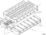
Es gibt nun verschiedene Möglichkeiten, die Lehre der vorliegenden Erfindung in vorteilhafter Weise auszugestalten und weiterzubilden. Dazu ist einerseits auf die dem Anspruch 1 nachgeordneten Ansprüche und andererseits auf die nachfolgende Erläuterung eines bevorzugten Ausführungsbeispiels der Erfindung anhand der Zeichnung zu verweisen. In Verbindung mit der Erläuterung des bevorzugten Ausführungsbeispiels der Erfindung anhand der Zeichnung werden auch im Allgemeinen bevorzugte Ausgestaltungen und Weiterbildungen der Lehre erläutert. In der Zeichnung zeigenThere are now various possibilities for designing and developing the teaching of the present invention in an advantageous manner. For this purpose, on the one hand to the claims subordinate to claim 1 and on the other hand to refer to the following explanation of a preferred embodiment of the invention with reference to the drawings. In conjunction with the explanation of the preferred embodiment of the invention with reference to the drawing, generally preferred embodiments and developments of the teaching are explained. In the drawing show
Der Aufspanntisch
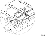
In den Tischelementen
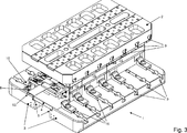
In
Die Anschläge
Hinsichtlich weiterer vorteilhafter Ausgestaltungen der erfindungsgemäßen Vorrichtung wird zur Vermeidung von Wiederholungen auf den allgemeinen Teil der Beschreibung sowie auf die beigefügten Ansprüche verwiesen.With regard to further advantageous embodiments of the device according to the invention, reference is made to avoid repetition to the general part of the specification and to the appended claims.
Schließlich sei ausdrücklich darauf hingewiesen, dass das voranstehend beschriebene Ausführungsbeispiel der erfindungsgemäßen Vorrichtung lediglich zur Erörterung der beanspruchten Lehre dient, diese jedoch nicht auf das Ausführungsbeispiel einschränkt.Finally, it should be expressly understood that the above-described embodiment of the device according to the invention is only for the purpose of discussion of the claimed teaching, but this does not limit the embodiment.
BezugszeichenlisteLIST OF REFERENCE NUMBERS
- 11
- Aufspanntischworktable
- 22
- Kopfplatte, StößelplatteTop plate, plunger plate
- 33
- Tischelementtable element
- 44
- Füllplattepanelboard
- 55
- Absatzparagraph
- 66
- Fixiermittelfixer
- 77
- Ausnehmungenrecesses
- 88th
- Anschlagattack
- 99
- Nutgroove
- 1010
- Erste ErhebungFirst survey
- 1111
- Zweite ErhebungSecond survey
- 1212
- Absatzparagraph
- 1313
- Ausnehmung, NutRecess, groove
- 1414
- Befestigungselemente, SchraubenFasteners, screws
- 1515
- Werkzeugmodultool module
- 1616
- Spannelementclamping element
- AA
- Ausnehmungrecess
Claims (8)
Priority Applications (1)
| Application Number | Priority Date | Filing Date | Title |
|---|---|---|---|
| DE201110086552 DE102011086552B4 (en) | 2011-11-17 | 2011-11-17 | Device for fastening tools in a press |
Applications Claiming Priority (1)
| Application Number | Priority Date | Filing Date | Title |
|---|---|---|---|
| DE201110086552 DE102011086552B4 (en) | 2011-11-17 | 2011-11-17 | Device for fastening tools in a press |
Publications (2)
| Publication Number | Publication Date |
|---|---|
| DE102011086552A1 DE102011086552A1 (en) | 2013-05-23 |
| DE102011086552B4 true DE102011086552B4 (en) | 2013-09-05 |
Family
ID=48221814
Family Applications (1)
| Application Number | Title | Priority Date | Filing Date |
|---|---|---|---|
| DE201110086552 Expired - Fee Related DE102011086552B4 (en) | 2011-11-17 | 2011-11-17 | Device for fastening tools in a press |
Country Status (1)
| Country | Link |
|---|---|
| DE (1) | DE102011086552B4 (en) |
Families Citing this family (1)
| Publication number | Priority date | Publication date | Assignee | Title |
|---|---|---|---|---|
| AT519352B1 (en) * | 2017-02-17 | 2018-06-15 | Dipl Ing Fh Gunter Felsner | Pressing tool base |
Citations (4)
| Publication number | Priority date | Publication date | Assignee | Title |
|---|---|---|---|---|
| EP0867275A1 (en) * | 1997-03-26 | 1998-09-30 | Rolf Hänggi | Punch press with tooling |
| KR20080088258A (en) * | 2007-03-29 | 2008-10-02 | 한국단자공업 주식회사 | Top Holder for Press Mold |
| KR20090055781A (en) * | 2007-11-29 | 2009-06-03 | 주식회사 선화정밀 | Die-plate for fixing a mold on press machine |
| DE202009008413U1 (en) * | 2009-06-16 | 2009-09-10 | Dold Kaltfließpressteile GmbH | Tool system for a forming press |
-
2011
- 2011-11-17 DE DE201110086552 patent/DE102011086552B4/en not_active Expired - Fee Related
Patent Citations (4)
| Publication number | Priority date | Publication date | Assignee | Title |
|---|---|---|---|---|
| EP0867275A1 (en) * | 1997-03-26 | 1998-09-30 | Rolf Hänggi | Punch press with tooling |
| KR20080088258A (en) * | 2007-03-29 | 2008-10-02 | 한국단자공업 주식회사 | Top Holder for Press Mold |
| KR20090055781A (en) * | 2007-11-29 | 2009-06-03 | 주식회사 선화정밀 | Die-plate for fixing a mold on press machine |
| DE202009008413U1 (en) * | 2009-06-16 | 2009-09-10 | Dold Kaltfließpressteile GmbH | Tool system for a forming press |
Also Published As
| Publication number | Publication date |
|---|---|
| DE102011086552A1 (en) | 2013-05-23 |
Similar Documents
| Publication | Publication Date | Title |
|---|---|---|
| EP2662645A2 (en) | Solar module holder | |
| EP2762271B1 (en) | Modular system for holding operating modules of a processing unit and processing installation | |
| DE102019219588A1 (en) | Fastening device and table with such a fastening device | |
| EP2292409B1 (en) | Tool holder, tool and work station with tool holder and tool attached to the same | |
| DE102005044951B4 (en) | slide arrangement | |
| EP1999830B1 (en) | Appliance installation kit for arrangement of an appliance in an electrical switchgear assembly | |
| DE102020101064B3 (en) | Workpiece clamping device | |
| DE19825426B4 (en) | In a T-slot deployable proximity switch or fastener for it | |
| DE102004055815B4 (en) | Mounting plate for electronic components | |
| EP3951114B1 (en) | Fixing device | |
| DE102011086552A1 (en) | Device for mounting tools in press, has stop elements which are assigned to worktable for orientation of tool module, and fixing agents are provided for fastening the tool module | |
| DE102006053831A1 (en) | Fastening device for to be arranged on a frame structure frame members, in particular solar modules | |
| DE102005000020B4 (en) | Arrangement for mounting an installation device insert on a support plate | |
| DE202010006771U1 (en) | Device for fastening components | |
| DE102018118344A1 (en) | Workpiece clamping system | |
| WO2021008850A1 (en) | Die cutting tool having processing module, stop clamp and connection clamp | |
| EP0479266B1 (en) | Support device in a cylinder gap | |
| DE102004029110B3 (en) | A method for more accurately fixing a handle to a door has a base plate, angle piece and handle each adjustable in one of three different directions | |
| DE102023120174A1 (en) | clamping system | |
| DE102011086560B4 (en) | Tool for a machine tool | |
| DE19852673C1 (en) | Variably mountable profile rod for use as a column, extension arm, traverse, strut or the like for devices | |
| EP2937190B1 (en) | Blank separation device with a pick up device and method for fixing at least one blank separation tool | |
| DE102023203422A1 (en) | connecting device, in particular angle connector | |
| DE10151912C1 (en) | Connector for profiled machine frame members has housing with screw actuated wedge to retain one frame member and a clamping bar to retain the second | |
| DE202024107466U1 (en) | Height adjustment device for a tool arrangement of a construction and/or industrial machine and tool arrangement of a construction and/or industrial machine with such a device |
Legal Events
| Date | Code | Title | Description |
|---|---|---|---|
| R012 | Request for examination validly filed | ||
| R016 | Response to examination communication | ||
| R018 | Grant decision by examination section/examining division | ||
| R020 | Patent grant now final |
Effective date: 20131206 |
|
| R119 | Application deemed withdrawn, or ip right lapsed, due to non-payment of renewal fee |