EP0863382B1 - Vorrichtung zur steuerung eines schrittmotors in einem messinstrument - Google Patents
Vorrichtung zur steuerung eines schrittmotors in einem messinstrument Download PDFInfo
- Publication number
- EP0863382B1 EP0863382B1 EP97927403A EP97927403A EP0863382B1 EP 0863382 B1 EP0863382 B1 EP 0863382B1 EP 97927403 A EP97927403 A EP 97927403A EP 97927403 A EP97927403 A EP 97927403A EP 0863382 B1 EP0863382 B1 EP 0863382B1
- Authority
- EP
- European Patent Office
- Prior art keywords
- angle data
- indication angle
- stepping motor
- indication
- data
- Prior art date
- Legal status (The legal status is an assumption and is not a legal conclusion. Google has not performed a legal analysis and makes no representation as to the accuracy of the status listed.)
- Expired - Lifetime
Links
- 238000012545 processing Methods 0.000 claims abstract description 79
- 230000008859 change Effects 0.000 claims abstract description 59
- 238000005259 measurement Methods 0.000 claims abstract description 44
- 238000006243 chemical reaction Methods 0.000 abstract description 19
- 244000126211 Hericium coralloides Species 0.000 description 11
- 239000011295 pitch Substances 0.000 description 11
- 230000005284 excitation Effects 0.000 description 5
- 238000000034 method Methods 0.000 description 5
- 230000003111 delayed effect Effects 0.000 description 4
- 238000010586 diagram Methods 0.000 description 4
- 238000012937 correction Methods 0.000 description 3
- 230000001965 increasing effect Effects 0.000 description 3
- 230000015572 biosynthetic process Effects 0.000 description 2
- 239000000446 fuel Substances 0.000 description 2
- 238000009499 grossing Methods 0.000 description 2
- 230000001133 acceleration Effects 0.000 description 1
- 239000000654 additive Substances 0.000 description 1
- 230000000996 additive effect Effects 0.000 description 1
- 230000000052 comparative effect Effects 0.000 description 1
- 238000012790 confirmation Methods 0.000 description 1
- 238000001514 detection method Methods 0.000 description 1
- 230000006872 improvement Effects 0.000 description 1
- 238000010348 incorporation Methods 0.000 description 1
- 230000001939 inductive effect Effects 0.000 description 1
- 230000007246 mechanism Effects 0.000 description 1
- 239000000203 mixture Substances 0.000 description 1
- 238000012544 monitoring process Methods 0.000 description 1
- 238000000053 physical method Methods 0.000 description 1
- 230000003449 preventive effect Effects 0.000 description 1
- 230000008569 process Effects 0.000 description 1
- 239000011347 resin Substances 0.000 description 1
- 229920005989 resin Polymers 0.000 description 1
- 230000004044 response Effects 0.000 description 1
- 238000005070 sampling Methods 0.000 description 1
- 230000007480 spreading Effects 0.000 description 1
- 238000003786 synthesis reaction Methods 0.000 description 1
Images


Classifications
-
- G—PHYSICS
- G01—MEASURING; TESTING
- G01R—MEASURING ELECTRIC VARIABLES; MEASURING MAGNETIC VARIABLES
- G01R7/00—Instruments capable of converting two or more currents or voltages into a single mechanical displacement
- G01R7/04—Instruments capable of converting two or more currents or voltages into a single mechanical displacement for forming a quotient
- G01R7/06—Instruments capable of converting two or more currents or voltages into a single mechanical displacement for forming a quotient moving-iron type
-
- G—PHYSICS
- G01—MEASURING; TESTING
- G01D—MEASURING NOT SPECIALLY ADAPTED FOR A SPECIFIC VARIABLE; ARRANGEMENTS FOR MEASURING TWO OR MORE VARIABLES NOT COVERED IN A SINGLE OTHER SUBCLASS; TARIFF METERING APPARATUS; MEASURING OR TESTING NOT OTHERWISE PROVIDED FOR
- G01D3/00—Indicating or recording apparatus with provision for the special purposes referred to in the subgroups
- G01D3/02—Indicating or recording apparatus with provision for the special purposes referred to in the subgroups with provision for altering or correcting the law of variation
-
- G—PHYSICS
- G01—MEASURING; TESTING
- G01D—MEASURING NOT SPECIALLY ADAPTED FOR A SPECIFIC VARIABLE; ARRANGEMENTS FOR MEASURING TWO OR MORE VARIABLES NOT COVERED IN A SINGLE OTHER SUBCLASS; TARIFF METERING APPARATUS; MEASURING OR TESTING NOT OTHERWISE PROVIDED FOR
- G01D7/00—Indicating measured values
-
- H—ELECTRICITY
- H02—GENERATION; CONVERSION OR DISTRIBUTION OF ELECTRIC POWER
- H02P—CONTROL OR REGULATION OF ELECTRIC MOTORS, ELECTRIC GENERATORS OR DYNAMO-ELECTRIC CONVERTERS; CONTROLLING TRANSFORMERS, REACTORS OR CHOKE COILS
- H02P8/00—Arrangements for controlling dynamo-electric motors rotating step by step
- H02P8/14—Arrangements for controlling speed or speed and torque
-
- H—ELECTRICITY
- H02—GENERATION; CONVERSION OR DISTRIBUTION OF ELECTRIC POWER
- H02P—CONTROL OR REGULATION OF ELECTRIC MOTORS, ELECTRIC GENERATORS OR DYNAMO-ELECTRIC CONVERTERS; CONTROLLING TRANSFORMERS, REACTORS OR CHOKE COILS
- H02P8/00—Arrangements for controlling dynamo-electric motors rotating step by step
- H02P8/36—Protection against faults, e.g. against overheating or step-out; Indicating faults
- H02P8/38—Protection against faults, e.g. against overheating or step-out; Indicating faults the fault being step-out
Definitions
- This invention relates to a driving apparatus for a stepping motor type instrument which is used as an instrument movement easy to control digitally instead of a movable coil type ammeter, cross coil type rotary magnet type ammeter or the like and more particularly to a stepping motor type instrument which measures and indicates such a measurement value as a traveling speed of a vehicle, engine rotation speed or the like based on a frequency signal input proportional thereto.
- a needle fixed to a driving end of an instrument movement is rotated corresponding to an input signal and a measurement value is indicated by a correspondence to an indicator panel marked with a numeral or graduation indicating a quantity to be measured.
- stepping operation of its magnet rotor is determined depending on the number of teeth of a comb tooth yoke and its formation pitch.
- the number of teeth is increased so as to make fine comb tooth pitch or so-called micro step driving is executed by driving signals.
- These styles are selected by an allowable size of the stepping motor depending on use . condition or cost including the driving circuit.
- a stepping motor is desired to be of small size regardless of any application purpose. Because a so-called PM type stepping motor is simply structured, the stepping motor has been easy to use because of improvement of the rotor magnet and comb tooth yoke.
- a stepping motor in which pulse signal control is carried out has attracted public attention as a movement of an indication instrument in which an indicated value is read out by a needle by correspondence to a graduation on the character panel.
- this is applicable for a traveling speed indicator or engine rotation meter of a vehicle and further by A/D processing on detection signals, it can be used also for a fuel gauge and thermometer.
- various proposals have been made for practical application as disclosed in Unexamined Published Japanese Patent Application No. 61-129575, Unexamined Published Japanese Patent Application No. 1-223312.
- a change amount of each predetermined frequency of input signal is obtained and a stepping drive is executed by each change amount.
- a position of the rotary magnet when power switch is ON is assumed to be an initial value (in an indication instrument, start point initialization processing is carried out by forcibly returning to a zero position on the character panel) and then the stepping drive is executed by each incremental or decremental amount of the input signal from this start point.
- the angular position is deviated from that controlled by stepping drive from a start point, namely deviated from a proper positional relation between the comb tooth yoke and magnetic pole of the rotary magnet, so that the angle may deviate by one pitch. If such an angular deviation or so-called step-out occurs, the proper angular position is never indicated until start point is initialized by turning on the power, so that an angle including an error due to the step-out is indicated.
- This kind of step-out phenomenon occurs when the rotary magnet does not follow up a change in input signal as well as due to mechanical deflection by external vibration or the like. That is, if a stepping drive torque relative to the rotary magnet of the stepping motor cannot be secured because of structural . reason, driving current limitation or the like or if a change in input signal relative to a limit of such a driving torque or angular speed is too large, the rotary magnet cannot follow up so that step-out occurs repeatedly and finally a large angular error is caused.
- the stepping motion corresponding to tooth pitch of the comb tooth yoke is basically employed and smoothness is obtained by correcting the waveform of the drive signals.
- a smoothing processing is only smoothing between the tooth pitches of the comb tooth yoke, and therefore the step-out due to pitch-over still occurs.
- a driving apparatus for stepping motor type instrument having a driving circuit for driving a stepping motor according to digital signal corresponding to a measurement quantity and for indicating the measurement quantity by pointing out a graduation on a character panel corresponding to the measurement quantity by means of a needle fixed on a driving shaft end of the stepping motor
- the driving apparatus comprising: processing means in which a digital signal corresponding to the measurement quantity is input and converted to an indication angle signal at a predetermined frequency; and delay means which obtains a difference between consecutive indication angle signals output at said frequency of the processing means and, if the difference is larger than a predetermined value, converts the signal so that its change is less than the predetermined value and outputs this signal as an indication angle signal.
- a driving apparatus for stepping motor type instrument having a driving circuit for driving a stepping motor according to a digital signal corresponding to a measurement quantity and for indicating the measurement quantity by pointing out a graduation on a character panel corresponding to the measurement quantity by means of a needle fixed on a driving shaft end of the stepping motor
- the driving apparatus comprising: a processing means for inputting a digital signal D corresponding to the measurement quantity and converting to an indication angle data A at a predetermined frequency; and delay means in which a difference ⁇ A of an updated indication angle data A n+1 output by the processing means relative to a previous indication angle data An is obtained, and if this difference ⁇ A is larger than a predetermined value C in terms of its absolute value, the updated indication angle data A n+1 is rewritten to A n +C or A n -C depending on its increase/decrease condition and this data is used as the previous indication angle data An for next processing so as to successively update and output the indication angle data.
- a driving apparatus for stepping motor type instrument having a driving circuit for driving a stepping motor according to a digital signal corresponding to a measurement quantity and for indicating the measurement quantity by pointing out a graduation on a character panel corresponding to the measurement quantity by means of a needle fixed on a driving shaft end of the stepping motor
- the driving apparatus comprising: processing means for inputting a digital signal D corresponding to the measurement quantity and converting to an indication angle data A at a predetermined frequency; and delay means in which a difference ⁇ A n of an updated indication angle data An+1 output by the processing means relative to a previous indication angle data A n and a difference ⁇ A n-1 of the previous indication angle data relative to an indication angle data An-1 before the previous one are obtained, and if a difference between these change rates is larger than a predetermined value X in terms of its absolute value, the updated indication angle data A n+1 is rewritten to 2A n -A n-1 +K or 2A n
- a driving apparatus for stepping motor type instrument mentioned above wherein the delay means carries out .
- FIG. 1 is a circuit block diagram showing an embodiment of the present invention
- FIG. 2 is a driving waveform diagram showing an example of the stepping motor driving signal waveform of the present invention
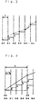
- FIG. 3 is a step waveform diagram for explaining a delay operation at a conversion frequency of indication data according to the present invention
- FIG. 4 is a division step waveform diagram for explaining delay processing at the division frequency of the indication data according to the present invention.
- FIG. 1 indicates a basic structure of the present . invention.
- a speedometer of a vehicle will be described as an example thereof.
- a frequency signal proportional to a traveling speed which is a quantity to be measured is input through an input terminal 1.
- Counting means 2 detects rise or fall of the input signal to count this based on a predetermined gate time (gate time type). Or it counts another high frequency clock signal (frequency measurement type) and calculates changing traveling speeds in the form of digital data D.
- the measured quantity obtained by the aforementioned counting means 2 is converted to an indication angle data A by processing means 3 at a predetermined conversion frequency T.
- Delay means 4 obtains an absolute value ⁇ A which is a difference between the aforementioned indication angle data An and an updated indication angle data A n+1 and indicates an increase or decrease at each conversion angle T.
- the predetermined value C is set to a step angle which can be followed easily without step-out of the stepping motor rotary magnet. Therefore, even if the rotary magnet cannot follow up so that it steps out because a change from A n to A n+1 is too large, when data output is carried out following actual change, driving without step-out is enabled by delay processing by delay means 4.
- the change in the indication angle data A by the delay processing drive provides a change in a digital data D corresponding to actually measured quantity as shown in FIG. 2 with a delayed indication.
- actually an angular speed of the needle of the indicator upon normal acceleration or deceleration does not increase extremely, so that an indication with a delay according to the present invention hardly affects the actual traveling.
- the indication angle data A subjected to delay processing by the delay means 4 as described above carries out appropriate waveform processing (micro-step waveform or phase conversion) for a two-phase excitation coil of the stepping motor through output means 5 and then is supplied. Then, the stepping motor type instrument 6 is driven so that a needle 9 fixed to the driving end is rotated by an angle indication corresponding to a graduation 8 of a character panel 7.
- the aforementioned respective means processes input signals appropriately as a driving circuit and drives the stepping motor type instrument 6.
- the processing means 3 can be constructed by means of a microcomputer including the counting means 2 and the delay means 4 so as to be capable of indicating a traveling speed by arbitrarily setting instrumental indicative characteristic.
- a memory (ROM) 10 storing an indication angle data A corresponding to the counted digital data D is provided, which fetches in the digital data D at a predetermined conversion frequency and outputs an indication angle data A at a memory address corresponding thereto.
- This processing means 3 is effective for a case in which a cheap IC having a slow processing speed is used for driving a single indication instrument such as a speedometer described here or a case in which, when time-division driving is carried out at the same time for other indication instruments (not shown) such as engine rotation meter, fuel gauge, thermometer, oil pressure gauge, and voltmeter (these indication instruments may be of stepping motor type instruments or may be combined with other instrumental movement such as a cross coil type instrument, a movable coil type instrument and the like), a processing frequency to be allocated to a traveling speed meter is insufficient for obtaining a smooth response.
- indication instruments may be of stepping motor type instruments or may be combined with other instrumental movement such as a cross coil type instrument, a movable coil type instrument and the like
- the storage about the indication angle data A which the . processing circuit 3 makes in the memory 10 includes data sufficient for obtaining a desired resolution capacity corresponding to a previous indication range from MIN to MAX of the digital data D, corresponding to a measurement quantity.
- the indication angle data A in the unit of 0.5 degrees is stored for the indication angle from 0° (MIN) to 360° (MAX) and this stored indication angle data An is read out at the predetermined conversion frequency T corresponding to the digital data D.
- an arbitrary two-phase signal can be set depending on the number of comb tooth yokes and pitch thereof.
- All driving waveform data corresponding to all indication angles of 360° can be stored in a voltage memory 12.
- voltage data of 60° each which is 1/6 of 360° as a stepping motor drive signal for the stepping motor type instrument 6 is prepared in the voltage memory 12 and this data is used in respective angular areas so as to reduce the memory capacity.
- the voltage waveform of the driving signal to be applied to the two-phase excitation coils A, B changes in the form of substantially SIN, COS shapes relative to the rotation angle of 360° of the needle 9 (combined magnet rotor) of the stepping motor type instrument 6, as shown in FIG. 2, so that this voltage waveform is spread over all angular areas a-f in which each angle is 60° .
- This spreading can be discriminated by the indication angle data A corresponding to the digital data D indication range.
- the voltage memory 12 is made to store a driving voltage data v (stored by angular difference of 60/128° from A0 corresponding to 0° to A60 corresponding to 60° ) having a resolution capacity in which 60° is divided by 128.
- this voltage data V is read out.
- each indication area is discriminated and at the same time, the voltage data V in the discrimination area is read out from the voltage memory 12 and an indication position of the indication instrument can be determined by combination with that confirmation area.
- the driving signal is not different depending on each indication area because magnet pole position of the magnet rotor is only moved to an excitation position within the area.
- the voltage data v can be read out from the voltage memory 12. For example, if the digital data D corresponds to the indication angle of 150°, the indication area is determined to be c and by reading out a data equivalent to 30° within this area from the voltage memory 12, the driving signal as shown in FIG. 2 is obtained.
- the driving waveform shown in FIG. 2 is a typical analogous waveform for obtaining smoothly mechanical step motion to be determined by the tooth pitch of the stepping motor.
- the SIN, COS waveforms are digitally fine waveforms.
- the pitch of the micro step is determined by a change speed of a measurement quantity indicated by an instrument or the angular speed of the needles and the processing capacity of a processing circuit.
- the present applicant has constructed concrete indication instruments and experimented their characteristics based on the basic composition.
- the stepping motor which is an instrument movement for use in the stepping motor type instrument 6 employs a well-known PM structure in which an excitation coil conducting two-phase driving waveform is wound around two overlaid resin bobbins while comb tooth yokes are provided on upper and lower portions of each bobbin and a magnet rotor is rotatably journaled in a hollow portion of the overlaid body of this bobbin.
- the processing circuit 3 carries out time-division driving which enables to drive other indication instruments and alarm by means of microcomputer.
- the conversion frequency T to be allocated to the traveling speedometer was set to 16 msec and the digital data D was changed with various angular speeds so as to observe a motion of the needle 9.
- the conversion frequency was temporarily set at 16 msec and the angular speed ⁇ was changed in a range from 10° /sec to 1080° /sec so that it was changed in the unit of 10° /sec in low speed range and in the unit of 100° /sec in high speed range. Under this condition, the frequency was increased from 16 msec in the unit of 1 msec as a short frequency and it was confirmed that the needle 9 was rotated smoothly.
- the digital data D of the counting means 2 which measures an angular speed which cannot be followed mechanically due to a structure of the stepping motor, that is, a change in • measurement quantity, is converted to the indication angle data An by the processing means 3. If a change rate to the updated indication angle data An+1 or a difference ⁇ A by the delay means 4 is larger than the predetermined value C set corresponding to a change in the angular speed inducing the step-out in terms of their absolute values, an increase/decrease direction of that change is determined and An+1 is rewritten to A n +C or A n -C and then output. Further, this data is successively updated as the indication angle data for next processing.
- a division data Bh is obtained by dividing a difference between continuous indication angle data front and back (A n+1 -A n ) by division number m.
- the same processing as ordinary delay processing at the frequency T is performed. If an absolute value ⁇ B h which is a difference of Bh+1 - Bh is larger than a predetermined value E, it is determined that the change width at the normal frequency T is very large and this value is rewritten to B h +E or B h -E depending on the incremental/decremental condition and output. Then, this data is used as the indication angle data Bh for the next processing, so that the update processing for the indication angle data is successively carried out.
- the data is updated at the division frequency of T/4 with respect to the conversion frequency T which enables the data to be allocated to the speedometer. If the change in the indication angle data at the conversion frequency T or the difference ⁇ A between continuous indication angle data front and back is large, the change in the data Bh at each division frequency T/4 also becomes large. If the change (B h+1 - B h ) in this B h is larger than the predetermined value E, additive processing of B h +E is carried out so that the same delay processing is carried out successively at each frequency of T/4.
- the delay processing is carried out by updating by adding the predetermined value C as shown by a solid line.
- the magnet rotor follows up its final indication position without step-out.
- the change of the indication angle data at the frequency T is very large like A4-A5, the follow-up is delayed.
- the same delay processing is carried out by the indication angle data Bh (from B0 to B4) at the division frequency T/4 and by adding the predetermined value E, the follow-up is made smooth thereby . preventing an occurrence of step-out excellently.
- the necessity of the delay processing by the division frequency and the number of division should be determined depending on the characteristic of a stepping motor to be applied and a measurement object, so as to prevent a step-out in an ordinary measurement/indication range. Further, they should be determined appropriately depending on sampling of processing means and conversion processing capacity so as to cover these matters.
- step is omitted.
- This method is basically structured to suppress the indication angle data A n or B n corresponding to a measurement quantity at the frequency T or division frequency T/m to a change rate difficult to produce step-out, and when the change rate of continuous data changes rapidly, the change characteristic changes in a direction that it largely inclines.
- the change is continued at a just previous change rate so as to follow up that change and further the delayed follow-up can be performed by giving a small increase or decrease. Consequently, it is possible to prevent an occurrence of step-out due to impossibility of follow-up.
- a data . change corresponding to a change in measurement quantity is large, an update signal to the stepping motor is delayed so as to follow up the rotary magnet thereby making it difficult to induce step-out.
- a complicated structure for restoring a step-out is not needed, that is, a reset mechanism in which zero return is forcibly executed in a full scale temporarily at the time of power ON and a stopper pin is provided so as to make a stop at this stopper pin and reset to an initial point is not needed or incorporation of an encoder for always monitoring for step-out and correction is not needed either. Consequently, a small size, cheap price indication instrument can be provided.
- the present invention utilizes an electric type movement for an indication instrument intended to be thin structured in order to input physical measurement quantity as electric signal and indicate by means of the needle corresponding to a character panel.
- this invention is applicable for an indication instrument which smoothly follows up a measurement quantity which changes rapidly.
Landscapes
- Engineering & Computer Science (AREA)
- Physics & Mathematics (AREA)
- General Physics & Mathematics (AREA)
- Power Engineering (AREA)
- Technology Law (AREA)
- Control Of Stepping Motors (AREA)
- Indication And Recording Devices For Special Purposes And Tariff Metering Devices (AREA)
Claims (5)
- Antriebsvorrichtung für ein Instrument bzw. Meßgerät mit Schrittmotor mit einem Antriebskreis zum Antreiben eines Schrittmotors in Abhängigkeit von einem digitalen Signal entsprechend einer Messgröße und zum Anzeigen der Messgröße durch Zeigen auf eine Gradeinteilung auf einer Zeichentafel entsprechend der Messgröße mittels einer auf einem Ende einer Antriebswelle des Schrittmotors befestigten Nadel, wobei die Antriebsvorrichtung zur Steuerung aufweist:Verarbeitungseinrichtung, in der ein digitales Signal entsprechend der Messgröße eingegeben und mit einer vorbestimmten Frequenz in ein Anzeigewinkelsignal umgewandelt wird; undVerzögerungseinrichtung, die eine Differenz zwischen aufeinander folgenden Anzeigewinkelsignalen, die mit der Frequenz von der Verarbeitungseinrichtung ausgegeben werden, erzielt und, falls die Differenz größer als ein vorbestimmter Wert ist, das Signal umwandelt, so dass dessen Veränderung geringer als der vorbestimmte Wert ist, und dieses Signal als ein Anzeigewinkelsignal ausgibt.
- Antriebsvorrichtung für ein Instrument mit Schrittmotor mit einem Antriebskreis zum Antreiben eines Schrittmotors in Abhängigkeit von einem digitalen Signal entsprechend einer Messgröße und zum Anzeigen der Messgröße durch Zeigen auf eine Gradeinteilung auf einer Zeichentafel entsprechend der Messgröße mittels einer auf einem Ende einer Antriebswelle des Schrittmotors befestigten Nadel, wobei die Antriebsvorrichtung umfaßt:Verarbeitungseinrichtung zum Eingeben eines digitalen Signals D entsprechend der Messgröße und zum Umwandeln in eine Anzeigewinkelangabe A mit einer vorbestimmten Frequenz; undVerzögerungseinrichtung, in der eine Differenz ΔA einer aktualisierten Anzeigewinkelangabe An+1, die von der Verarbeitungseinrichtung relativ zu einer vorherigen Anzeigewinkelangabe An ausgegeben wurde, erzielt wird, und falls diese Differenz ΔA größer ist als ein vorbestimmter Wert C bezogen auf dessen absoluten Wert, die aktualisierte Anzeigewinkelangabe An+1 je nach deren Zunahme-/Abnahmezustand zu An+C oder An-C regeneriert bzw. überschreibt und diese Angabe für die nächste Verarbeitung als die vorherige Anzeigewinkelangabe An verwendet wird, um nacheinander die Anzeigewinkelangaben zu aktualisieren und auszugeben.
- Antriebsvorrichtung für ein Instrument mit Schrittmotor mit einem Antriebskreis zum Antreiben eines Schrittmotors in Abhängigkeit von einem digitalen Signal entsprechend einer Messgröße und zum Anzeigen der Messgröße durch Zeigen auf eine Gradeinteilung auf einer Zeichentafel entsprechend der Messgröße mittels einer auf einem Ende einer Antriebswelle des Schrittmotors befestigten Nadel, wobei die Antriebsvorrichtung aufweist:Verarbeitungseinrichtung zum Eingeben eines digitalen Signals D entsprechend der Messgröße und zum Umwandeln in eine Anzeigewinkelangabe A mit einer vorbestimmten Frequenz; undVerzögerungseinrichtung, in der eine Differenz ΔAn einer aktualisierten Anzeigewinkelangabe An+1, die von der Verarbeitungseinrichtung relativ zu einer vorherigen Anzeigewinkelangabe An ausgegeben wurde, und eine Differenz ΔAn-1 der vorherigen Anzeigewinkelangabe relativ zu einer Anzeigewinkelangabe An-1 vor der vorherigen erzielt werden, und falls eine Differenz zwischen diesen Änderungsraten größer als ein vorbestimmter Wert X bezogen auf dessen absoluten Wert ist, die aktualisierte Anzeigewinkelangabe An+1 je nach deren Zunahme-/Abnahmezustand zu 2An-An-1+K oder 2An-An-1-K (wobei 0<K=<X) regeneriert bzw. überschreibt und diese Angabe für die nächste Verarbeitung als die Anzeigewinkelangabe An vor der vorherigen verwendet wird, um nacheinander die Anzeigewinkelangabe zu aktualisieren und auszugeben.
- Antriebsvorrichtung für ein Instrument mit Schrittmotor nach Anspruch 2 oder 3, wobei die Verzögerungseinrichtung eine Zerlegungsschrittverarbeitung für (An+1-An)/m=Bh jeweils mit einer Frequenz T/m (m ist eine ganze Zahl von 2 oder mehr), die kürzer als die Aktualisierungsfrequenz T der Anzeigewinkelangabe An ist, durchführt, und wenn ein absoluter Wert ΔBh einer Differenz von Bh+1-Bh größer als ein vorbestimmter Wert E ist, die Anzeigewinkelangabe Bh+1 je nach deren Zunahme-/Abnahmezustand zu Bh+E oder Bh-E regeneriert bzw. überschrieben wird, und diese Angabe für die nächste Verarbeitung als die Anzeigewinkelangabe Bh verwendet wird, um die Anzeigewinkelangabe nacheinander zu aktualisieren.
- Antriebsvorrichtung für ein Instrument mit Schrittmotor nach Anspruch 2 oder 3, wobei die Verzögerungseinrichtung eine Zerlegungsschrittverarbeitung für (An+1-An)/m=Bh jeweils mit einer Frequenz T/m (m ist eine ganze Zahl von 2 oder mehr), die kürzer als die Aktualisierungsfrequenz T der Anzeigewinkelangabe An ist, durchführt, und eine Änderungsrate einer Differenz ΔBh von Bh+1-Bh und einer Differenz ΔBh-1 von Bh-Bh-1 erzielt werden, und falls eine Differenz dieser Änderungsraten größer als ein vorbestimmter Wert Y ist, die Anzeigewinkelangabe Bh+1 je nach deren Zunahme-/Abnahmezustand zu 2Bh-Bh-1+L oder 2Bh-Bh-1-L (wobei 0<L=<Y) regeneriert bzw. überschrieben wird, und diese Angabe für die nächste Verarbeitung als die Anzeigewinkelangabe Bh verwendet wird, um die Anzeigewinkelangabe nacheinander zu aktualisieren.
Applications Claiming Priority (4)
| Application Number | Priority Date | Filing Date | Title |
|---|---|---|---|
| JP16974096 | 1996-06-28 | ||
| JP169740/96 | 1996-06-28 | ||
| JP8169740A JP2953502B2 (ja) | 1996-06-28 | 1996-06-28 | ステッピングモータ式計器の駆動装置 |
| PCT/JP1997/002126 WO1998000684A1 (fr) | 1996-06-28 | 1997-06-19 | Dispositif de commande d'un appareil du type moteur pas a pas |
Publications (3)
| Publication Number | Publication Date |
|---|---|
| EP0863382A1 EP0863382A1 (de) | 1998-09-09 |
| EP0863382A4 EP0863382A4 (de) | 1998-09-23 |
| EP0863382B1 true EP0863382B1 (de) | 2001-12-05 |
Family
ID=15891974
Family Applications (1)
| Application Number | Title | Priority Date | Filing Date |
|---|---|---|---|
| EP97927403A Expired - Lifetime EP0863382B1 (de) | 1996-06-28 | 1997-06-19 | Vorrichtung zur steuerung eines schrittmotors in einem messinstrument |
Country Status (8)
| Country | Link |
|---|---|
| US (1) | US5994893A (de) |
| EP (1) | EP0863382B1 (de) |
| JP (1) | JP2953502B2 (de) |
| KR (1) | KR100293115B1 (de) |
| CN (1) | CN1088832C (de) |
| AT (1) | ATE210278T1 (de) |
| DE (1) | DE69708835T2 (de) |
| WO (1) | WO1998000684A1 (de) |
Families Citing this family (15)
| Publication number | Priority date | Publication date | Assignee | Title |
|---|---|---|---|---|
| JP3198503B2 (ja) * | 1998-09-30 | 2001-08-13 | 日本精機株式会社 | 計器の駆動方法 |
| ATE383581T1 (de) * | 1999-09-22 | 2008-01-15 | Ebm Papst St Georgen Gmbh & Co | Verfahren zur messung einer frequenzinformation, insbesondere einer drehzahlinformation bei einem motors, und vorrichtung zur durchführung eines solchen verfahrens |
| JP2002039808A (ja) * | 2000-07-25 | 2002-02-06 | Denso Corp | 車両用指示計器 |
| US6624608B2 (en) * | 2001-02-23 | 2003-09-23 | Denso Corporation | Indicating instrument for a vehicle |
| JP3828785B2 (ja) * | 2001-11-19 | 2006-10-04 | 矢崎総業株式会社 | 初期化駆動装置 |
| JP4386649B2 (ja) * | 2003-01-21 | 2009-12-16 | 株式会社デンソー | 指針計器 |
| CN101373947B (zh) * | 2007-08-22 | 2012-05-23 | 比亚迪股份有限公司 | 一种步进电机速度的控制方法、装置及系统 |
| US7816883B2 (en) * | 2007-10-09 | 2010-10-19 | Delphi Technologies, Inc. | Return-to-zero control method for a stepper motor |
| JP4423339B2 (ja) * | 2007-12-27 | 2010-03-03 | カルソニックカンセイ株式会社 | ステッピングモータ制御装置およびステッピングモータの駆動制御方法 |
| CN101777216B (zh) * | 2010-01-27 | 2012-11-07 | 管于球 | 射频ic卡水表 |
| CN101738234B (zh) * | 2010-01-27 | 2012-08-08 | 管于球 | 全电子数字式自来水表 |
| EP2554951A4 (de) | 2010-04-02 | 2014-09-24 | Yaskawa Denki Seisakusho Kk | Signalprozessor, kodiergerät und motorsystem |
| CN106341649B (zh) * | 2015-07-07 | 2019-06-18 | 杭州海康威视数字技术股份有限公司 | 云台控制方法和装置 |
| JP6623878B2 (ja) * | 2016-03-24 | 2019-12-25 | 日本精機株式会社 | 車両情報取得装置及び車両情報取得方法 |
| CN110108311B (zh) * | 2019-04-30 | 2024-08-16 | 中国人民解放军海军潜艇学院 | 可修正指针式旋转指示器 |
Family Cites Families (5)
| Publication number | Priority date | Publication date | Assignee | Title |
|---|---|---|---|---|
| US3868570A (en) * | 1973-09-28 | 1975-02-25 | Chrysler Corp | Electronic digital speedometer |
| JP2742270B2 (ja) * | 1988-09-21 | 1998-04-22 | ローム株式会社 | メータ駆動装置 |
| JPH04133200A (ja) * | 1990-09-26 | 1992-05-07 | Yokokawa Nabitetsuku Kk | デジタル通信によるアナログ表示装置 |
| GB2292026B (en) * | 1994-07-22 | 1999-02-10 | Delco Electronic Overseas Corp | Stepper motor circuit and method of operating a stepper motor |
| JP3048035B2 (ja) * | 1994-11-29 | 2000-06-05 | 矢崎総業株式会社 | 針式表示装置 |
-
1996
- 1996-06-28 JP JP8169740A patent/JP2953502B2/ja not_active Expired - Lifetime
-
1997
- 1997-06-19 EP EP97927403A patent/EP0863382B1/de not_active Expired - Lifetime
- 1997-06-19 WO PCT/JP1997/002126 patent/WO1998000684A1/ja active IP Right Grant
- 1997-06-19 DE DE69708835T patent/DE69708835T2/de not_active Expired - Lifetime
- 1997-06-19 CN CN97190788A patent/CN1088832C/zh not_active Expired - Lifetime
- 1997-06-19 US US09/029,394 patent/US5994893A/en not_active Expired - Lifetime
- 1997-06-19 AT AT97927403T patent/ATE210278T1/de active
- 1997-06-19 KR KR1019980701438A patent/KR100293115B1/ko not_active IP Right Cessation
Also Published As
| Publication number | Publication date |
|---|---|
| JPH1019598A (ja) | 1998-01-23 |
| DE69708835T2 (de) | 2002-08-01 |
| CN1088832C (zh) | 2002-08-07 |
| WO1998000684A1 (fr) | 1998-01-08 |
| CN1196792A (zh) | 1998-10-21 |
| JP2953502B2 (ja) | 1999-09-27 |
| DE69708835D1 (de) | 2002-01-17 |
| KR19990044202A (ko) | 1999-06-25 |
| ATE210278T1 (de) | 2001-12-15 |
| EP0863382A1 (de) | 1998-09-09 |
| US5994893A (en) | 1999-11-30 |
| EP0863382A4 (de) | 1998-09-23 |
| KR100293115B1 (ko) | 2002-02-28 |
Similar Documents
| Publication | Publication Date | Title |
|---|---|---|
| EP0863382B1 (de) | Vorrichtung zur steuerung eines schrittmotors in einem messinstrument | |
| KR100499729B1 (ko) | 차량용 지시계기 | |
| JP3013775B2 (ja) | ステッピングモータ式計器の駆動装置 | |
| WO2003056696A1 (en) | Method and apparatus for detecting a stall condition in a stepping motor | |
| US5665897A (en) | Method of calibrating and zeroing stepper motor gauges | |
| US5847475A (en) | Method of correction between electrical phase angle and mechanical output angle of stepper motor | |
| US5783939A (en) | Stepper motor gauge calibration by AC feedback | |
| US4884058A (en) | Combination indicator apparatus for automotive vehicle | |
| KR970010004B1 (ko) | 교차코일형 가동자석식계기 | |
| US5359284A (en) | Air core gauge magnetic hysteresis compensation | |
| JP2002250641A (ja) | 車両用指示計器 | |
| JP2000018975A (ja) | ステッピングモータ式計器装置 | |
| JP3106462B2 (ja) | 指示計器の駆動装置 | |
| JPH0664088B2 (ja) | クロスコイル形計器の駆動装置 | |
| JP3106463B2 (ja) | 駆動装置 | |
| JPH10311742A (ja) | 位置検出センサ | |
| JP3351654B2 (ja) | 三角関数データ変換回路およびメータ装置 | |
| JP3224009B2 (ja) | 指針式表示装置 | |
| KR100537265B1 (ko) | 계기의 구동방법 | |
| US20090261772A1 (en) | Advanced method for stepper motor speed determination | |
| JP2006258450A (ja) | 計器装置 | |
| JPH09236620A (ja) | 計器装置 | |
| JPH0387666A (ja) | 交差コイル型計器 | |
| JP2003294779A (ja) | 風向、風速指示装置 | |
| JPH06249881A (ja) | 3相コイル式回転駆動装置 |
Legal Events
| Date | Code | Title | Description |
|---|---|---|---|
| PUAI | Public reference made under article 153(3) epc to a published international application that has entered the european phase |
Free format text: ORIGINAL CODE: 0009012 |
|
| 17P | Request for examination filed |
Effective date: 19980213 |
|
| AK | Designated contracting states |
Kind code of ref document: A1 Designated state(s): AT BE CH DE FR GB IT LI NL SE |
|
| A4 | Supplementary search report drawn up and despatched | ||
| AK | Designated contracting states |
Kind code of ref document: A4 Designated state(s): AT BE CH DE FR GB IT LI NL SE |
|
| GRAG | Despatch of communication of intention to grant |
Free format text: ORIGINAL CODE: EPIDOS AGRA |
|
| 17Q | First examination report despatched |
Effective date: 20010208 |
|
| GRAG | Despatch of communication of intention to grant |
Free format text: ORIGINAL CODE: EPIDOS AGRA |
|
| GRAH | Despatch of communication of intention to grant a patent |
Free format text: ORIGINAL CODE: EPIDOS IGRA |
|
| GRAH | Despatch of communication of intention to grant a patent |
Free format text: ORIGINAL CODE: EPIDOS IGRA |
|
| GRAA | (expected) grant |
Free format text: ORIGINAL CODE: 0009210 |
|
| AK | Designated contracting states |
Kind code of ref document: B1 Designated state(s): AT BE CH DE FR GB IT LI NL SE |
|
| PG25 | Lapsed in a contracting state [announced via postgrant information from national office to epo] |
Ref country code: NL Free format text: LAPSE BECAUSE OF FAILURE TO SUBMIT A TRANSLATION OF THE DESCRIPTION OR TO PAY THE FEE WITHIN THE PRESCRIBED TIME-LIMIT Effective date: 20011205 Ref country code: LI Free format text: LAPSE BECAUSE OF FAILURE TO SUBMIT A TRANSLATION OF THE DESCRIPTION OR TO PAY THE FEE WITHIN THE PRESCRIBED TIME-LIMIT Effective date: 20011205 Ref country code: CH Free format text: LAPSE BECAUSE OF FAILURE TO SUBMIT A TRANSLATION OF THE DESCRIPTION OR TO PAY THE FEE WITHIN THE PRESCRIBED TIME-LIMIT Effective date: 20011205 Ref country code: BE Free format text: LAPSE BECAUSE OF FAILURE TO SUBMIT A TRANSLATION OF THE DESCRIPTION OR TO PAY THE FEE WITHIN THE PRESCRIBED TIME-LIMIT Effective date: 20011205 Ref country code: AT Free format text: LAPSE BECAUSE OF FAILURE TO SUBMIT A TRANSLATION OF THE DESCRIPTION OR TO PAY THE FEE WITHIN THE PRESCRIBED TIME-LIMIT Effective date: 20011205 |
|
| REF | Corresponds to: |
Ref document number: 210278 Country of ref document: AT Date of ref document: 20011215 Kind code of ref document: T |
|
| REG | Reference to a national code |
Ref country code: CH Ref legal event code: EP |
|
| REG | Reference to a national code |
Ref country code: GB Ref legal event code: IF02 |
|
| REF | Corresponds to: |
Ref document number: 69708835 Country of ref document: DE Date of ref document: 20020117 |
|
| PG25 | Lapsed in a contracting state [announced via postgrant information from national office to epo] |
Ref country code: SE Free format text: LAPSE BECAUSE OF FAILURE TO SUBMIT A TRANSLATION OF THE DESCRIPTION OR TO PAY THE FEE WITHIN THE PRESCRIBED TIME-LIMIT Effective date: 20020305 |
|
| NLV1 | Nl: lapsed or annulled due to failure to fulfill the requirements of art. 29p and 29m of the patents act | ||
| ET | Fr: translation filed | ||
| REG | Reference to a national code |
Ref country code: CH Ref legal event code: PL |
|
| PLBE | No opposition filed within time limit |
Free format text: ORIGINAL CODE: 0009261 |
|
| STAA | Information on the status of an ep patent application or granted ep patent |
Free format text: STATUS: NO OPPOSITION FILED WITHIN TIME LIMIT |
|
| 26N | No opposition filed | ||
| REG | Reference to a national code |
Ref country code: FR Ref legal event code: PLFP Year of fee payment: 20 |
|
| PGFP | Annual fee paid to national office [announced via postgrant information from national office to epo] |
Ref country code: GB Payment date: 20160615 Year of fee payment: 20 Ref country code: DE Payment date: 20160614 Year of fee payment: 20 |
|
| PGFP | Annual fee paid to national office [announced via postgrant information from national office to epo] |
Ref country code: FR Payment date: 20160516 Year of fee payment: 20 |
|
| PGFP | Annual fee paid to national office [announced via postgrant information from national office to epo] |
Ref country code: IT Payment date: 20160621 Year of fee payment: 20 |
|
| REG | Reference to a national code |
Ref country code: DE Ref legal event code: R071 Ref document number: 69708835 Country of ref document: DE |
|
| REG | Reference to a national code |
Ref country code: GB Ref legal event code: PE20 Expiry date: 20170618 |
|
| PG25 | Lapsed in a contracting state [announced via postgrant information from national office to epo] |
Ref country code: GB Free format text: LAPSE BECAUSE OF EXPIRATION OF PROTECTION Effective date: 20170618 |