EP0860892A2 - Récepteur radio à stabilisation de connecteur d'antenne - Google Patents
Récepteur radio à stabilisation de connecteur d'antenne Download PDFInfo
- Publication number
- EP0860892A2 EP0860892A2 EP98101133A EP98101133A EP0860892A2 EP 0860892 A2 EP0860892 A2 EP 0860892A2 EP 98101133 A EP98101133 A EP 98101133A EP 98101133 A EP98101133 A EP 98101133A EP 0860892 A2 EP0860892 A2 EP 0860892A2
- Authority
- EP
- European Patent Office
- Prior art keywords
- radio receiver
- antenna
- receiver
- junction box
- radio
- Prior art date
- Legal status (The legal status is an assumption and is not a legal conclusion. Google has not performed a legal analysis and makes no representation as to the accuracy of the status listed.)
- Granted
Links
Images


Classifications
-
- H—ELECTRICITY
- H01—ELECTRIC ELEMENTS
- H01Q—ANTENNAS, i.e. RADIO AERIALS
- H01Q21/00—Antenna arrays or systems
- H01Q21/30—Combinations of separate antenna units operating in different wavebands and connected to a common feeder system
-
- H—ELECTRICITY
- H01—ELECTRIC ELEMENTS
- H01Q—ANTENNAS, i.e. RADIO AERIALS
- H01Q1/00—Details of, or arrangements associated with, antennas
- H01Q1/12—Supports; Mounting means
- H01Q1/1207—Supports; Mounting means for fastening a rigid aerial element
-
- H—ELECTRICITY
- H01—ELECTRIC ELEMENTS
- H01R—ELECTRICALLY-CONDUCTIVE CONNECTIONS; STRUCTURAL ASSOCIATIONS OF A PLURALITY OF MUTUALLY-INSULATED ELECTRICAL CONNECTING ELEMENTS; COUPLING DEVICES; CURRENT COLLECTORS
- H01R2201/00—Connectors or connections adapted for particular applications
- H01R2201/02—Connectors or connections adapted for particular applications for antennas
Definitions
- the invention relates to a radio receiver according to the Genus of the main claim.
- the radio receiver according to the invention with the features of The main claim has the advantage that a uniform antenna connection module with defined Antenna socket positions can be provided, that only must be adapted to the respective device type on the receiver side, however standardized antenna sockets on the antenna side and can have connection positions. That way expensive cable tails outside the housing of the Radio receiver not only for the radio receiver part but also for others integrated in the radio receiver Receiving parts for example for mobile radio and Position determination recipient avoided.
- junction box is not in the housing of the radio receiver is integrated, but is positively connected to this.
- the modularization of the antenna connection becomes the manufacture of the radio receiver further simplified, whereby additional costs can be saved.
- Another advantage is that a Antenna connection, the cable-shaped from the back or -side wall of the radio receiver is led out through Connection to the corresponding antenna socket of the Junction box stabilized in its position or fixed and is protected from external influences. In this way this antenna connection is easier and faster accessible, which increases the comfort for the user becomes.
- the junction box has an outer Holding device and that in the outer Holding device an antenna tube especially for Broadcast reception is feasible. In this way, through the Junction box additionally an antenna in its position be stabilized. This will, for example, by Vibrations caused the antenna tube to come loose from the associated antenna socket of the radio receiver prevented.
- the at least one Antenna socket on the connection box and the connecting line by holding devices in the junction box in their position are fixed. This way the at least one Antenna socket and the connecting line continue stabilized so that in particular the axial forces from Junction box to be included, at least one Antenna socket and the connecting cable are not loaded and therefore wear less.
- junction box with the Radio receiver rear or side wall is screwed. This way is an easy one Possibility to connect the junction box with the Radio receiver rear or side wall given.
- junction box in two pieces, preferably by injection molding manufactured housing part and preferably also is made of injection molded closure cover.
- the connection box is also particularly stable and low wear.
- junction box is HF-like is shielded. In this way the coupling of high-frequency interference on the junction box prevented.
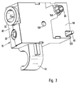
- FIG. 1 shows a front view of a Junction box
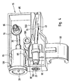
- Figure 2 one on the rear wall of a Radio receiver screwed connection box
- Figure 3 a rear view of a junction box
- Figure 4 a Interior view of a junction box without cover
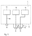
- Figure 5 is a block diagram of an inventive Radio receiver.
- 1 denotes a car radio Radio receiver with a radio receiving part 115, one Radiotelephone 30 and a receiver 40 for Position determination, in the present embodiment trained as a GPS receiver (Global Positioning System) is.
- GPS receiver Global Positioning System
- Other modules for data input and output of the Radio receiver 1 are known to those skilled in the art Executed in this way and not shown in FIG. 5.
- a Back wall 10 of the radio receiver 1 is a first Antenna socket 60 for the radio receiving part 115 arranged and with the radio receiving part 115 via a first connecting line 120 connected.
- a junction box 15th with a second antenna socket 20 and a third Antenna socket 25 includes.
- the second antenna socket 20 is thereby via a second connecting line 35 with the Radio telephone 30 connected and the third antenna socket 25 is via a third connecting line 45 to the GPS receiver 40 connected.
- the junction box 15 is shown. It exists from a housing part 85 and a closure cap 90. Thereby the junction box 15 is cuboid, wherein the closure cover 90 is a long side of the connection box 15 covers. According to Figure 2, the junction box 15 is on its cover 90 over one at the Cover 90 opposite side of the Terminal box 15 accessible screw 100 with the Back wall 10 of the radio receiver 1 non-positively screwed. There are also other non-positive ones Connection types, such as gluing possible. On one of its narrow sides has the junction box 15 second antenna socket 20 and third antenna socket 25 on a space-saving feeding of each Antenna cable parallel or at a small angle to Allow rear wall 10.
- connection box 15 has an outer holding device on a further narrow side 50 which, according to FIG. 2, has an antenna tube 55 for Radio reception in also to the rear wall 10 parallel guidance or small angle holds.
- the Antenna tube 55 is at the level of the first antenna socket 60 angled at right angles and with the first Antenna socket 60 on the rear wall 10 of the Broadcast receiver 1 connected.
- FIG. 3 is a rear view of the connection box 15 shown.
- the cover 90 Screw opening 110 for receiving the screw 100 shown.
- the cap 90 Recognizable connector module 95 through which the second Connecting line 35 with a mating plug contact Rear wall 10 of the radio receiver 1 is connected. Also protrudes from an opening 125 of the closure cover 90 out the third connecting line 45, which via a Opening the rear wall 10 to the GPS receiver 40 is led.
- FIG. 4 the interior of the junction box 15 and the Housing part 85 shown.
- the housing part 85 has on the narrow side with the two antenna sockets 20, 25 a first antenna receptacle 130 and a second Antenna socket opening 135 on.
- the first Antenna socket opening 130 serves to accommodate the second antenna socket 20 and the second Antenna jack opening 135 is used to hold the third Antenna socket 25.
- An additional bracket experiences the second antenna socket 20 by a first Holding device 65 inside the housing part 85.
- the through an opening 140 of the closure cover 90 according to FIG. 3 guided plug test module 95 is according to Figure 4 on the second Connection line 35 with the second antenna socket 20 connected and is a second holding device 70 in Housing part 85 stabilized.
- the first holding device 65 encompasses the cylindrical second antenna socket 20 through opposite and with that Sealing cover 90 facing away from the long side of the housing part 85 connected correspondingly curved webs.
- the second Holding device 70 encloses the plug module 95 ring-shaped and is also with the cap 90th opposite long side of the housing part 85 connected.
- the third connecting line 45 is in the housing part 85 by a third holding device 75 in the form of a Cable duct led.
- the also circular cylindrical trained third antenna socket 25 is replaced by a fourth Holding device 80 fixed in position in the housing part 85.
- the fourth holding device 80 encloses the third Antenna socket 25 also by means of two each other opposite and with the cover 90th opposite long side of the housing part 85 connected webs.
- the housing part 85 there is still one cylindrical screw guide 105 arranged for Recording the screw 100 is used.
- the four Holding devices 65, 70, 75, 80 in the junction box 15 are So the second and the third antenna socket 20, 25 and second and third connecting line 35, 45 in their Fixed location.
- the Junction box 15 also on a side wall of the housing Radio receiver 1 may be arranged.
- the housing part 85 and the closure cover 90 are preferably made from injection molding. It can Housing part 85 glued to the closure cover 90 or welded or otherwise connected. A Connection of the housing part 85 with the cover 90 is even if both parts are screw 100 non-positively with the rear wall 10 of the Broadcast receiver 1 are connected.
- a junction box 15 formed of plastic Insert 200 made of metal or bimetal high-frequency shielding arranged between the second and the third antenna socket 20, 25 and the second and third connecting lines 35, 45 are in the otherwise.
- the four Holding devices 65, 70, 75, 80 and the two Antenna jack openings 130, 135 are the second and the third antenna socket 20, 25 and the second and third Connection line 35, 45 so in the junction box 15th used that mainly axial forces from the junction box 15 are recorded and thus the wear of the two Antenna sockets 20, 25 and the two connecting lines 35, 45 is at least reduced.
- the four Holding devices 65, 70, 75, 80 and the two Antenna jack openings 130, 135 become the second and the third antenna socket 20, 25 and the second and the third connecting line 35, 45 also held in height and so fixed in their position.
- the terminal box 15 With the help of the described terminal box 15 is a standardized positioning of the second and third Antenna socket 20, 25 possible, so that for example Checking the function of the radio receiver 1 in the Manufacturing through a single, with the two Antenna sockets 20, 25 of the connection box 15 to be connected Adapter assembly is possible.
- the junction box 15 can, depending on the type of device Broadcast receiver 1, that is, depending on the number the arranged in the radio receiver 1 and Receiver modules, equipped with the necessary antenna sockets will.
- the first antenna socket 60 for the Radio receiving part 115 can in the junction box 15 be arranged.
Landscapes
- Details Of Aerials (AREA)
- Structure Of Receivers (AREA)
- Fittings On The Vehicle Exterior For Carrying Loads, And Devices For Holding Or Mounting Articles (AREA)
Applications Claiming Priority (2)
| Application Number | Priority Date | Filing Date | Title |
|---|---|---|---|
| DE1997106709 DE19706709C2 (de) | 1997-02-20 | 1997-02-20 | Rundfunkempfänger |
| DE19706709 | 1997-02-20 |
Publications (3)
| Publication Number | Publication Date |
|---|---|
| EP0860892A2 true EP0860892A2 (fr) | 1998-08-26 |
| EP0860892A3 EP0860892A3 (fr) | 2000-07-19 |
| EP0860892B1 EP0860892B1 (fr) | 2006-03-29 |
Family
ID=7820932
Family Applications (1)
| Application Number | Title | Priority Date | Filing Date |
|---|---|---|---|
| EP19980101133 Expired - Lifetime EP0860892B1 (fr) | 1997-02-20 | 1998-01-23 | Récepteur radio à stabilisation de connecteur d'antenne |
Country Status (2)
| Country | Link |
|---|---|
| EP (1) | EP0860892B1 (fr) |
| DE (2) | DE19706709C2 (fr) |
Families Citing this family (1)
| Publication number | Priority date | Publication date | Assignee | Title |
|---|---|---|---|---|
| DE10352169A1 (de) | 2003-11-05 | 2005-06-09 | Siemens Ag | Adapter für Autoradios |
Family Cites Families (5)
| Publication number | Priority date | Publication date | Assignee | Title |
|---|---|---|---|---|
| US4881910A (en) * | 1987-09-21 | 1989-11-21 | Walter Odemer Co., Inc. | Quick release minimum profile shuttle for vehicle radios and tape players |
| GB2249447B (en) * | 1990-10-30 | 1995-05-24 | Technophone Ltd | Combined broadcast radio receiver and radio telephone |
| IT221697Z2 (it) * | 1991-02-27 | 1994-09-15 | Siria Srl | Dispositivo di collegamento d'antenna per autoradio |
| JP2793380B2 (ja) * | 1991-06-17 | 1998-09-03 | 富士通株式会社 | 同軸マルチ混在コネクタ |
| DE19644648C1 (de) * | 1996-10-26 | 1998-05-20 | Bosch Gmbh Robert | Rundfunkempfänger |
-
1997
- 1997-02-20 DE DE1997106709 patent/DE19706709C2/de not_active Expired - Fee Related
-
1998
- 1998-01-23 DE DE59813464T patent/DE59813464D1/de not_active Expired - Lifetime
- 1998-01-23 EP EP19980101133 patent/EP0860892B1/fr not_active Expired - Lifetime
Also Published As
| Publication number | Publication date |
|---|---|
| EP0860892B1 (fr) | 2006-03-29 |
| EP0860892A3 (fr) | 2000-07-19 |
| DE19706709C2 (de) | 2003-12-18 |
| DE19706709A1 (de) | 1998-09-03 |
| DE59813464D1 (de) | 2006-05-18 |
Similar Documents
| Publication | Publication Date | Title |
|---|---|---|
| DE60205562T2 (de) | Richtungsfreie Zündpille-Anschlusseinrichtung für Kraftfahrzeug-Luftsacksysteme | |
| EP1851567B1 (fr) | Capteur ultrasonore modulaire | |
| DE10393763B4 (de) | Verbinderanordnung mit einer dielektrischen Abdeckung | |
| EP3383709B1 (fr) | Système de guide-câble conçu pour des câbles de connexion d'un module de coussin gonflable, câblage, module de coussin gonflable et volant ou véhicule équipé d'un tel système de guide-câble | |
| DE69809505T2 (de) | Verbindungsanordnung eines Verbinders | |
| EP2762839B1 (fr) | Dispositif d'adaptateur doté d'une interface mécanique pour un boîtier d'appareil de mesure | |
| DE102011081016A1 (de) | Sensormodul und Verfahren zur Herstellung eines Sensormoduls | |
| WO2007131826A1 (fr) | Dispositif de fixation et procédé de fixation pour une antenne de véhicule | |
| DE102016223642A1 (de) | Eingriffsstruktur, elektronisches Bauelementmodul und Elektroanschlusskasten | |
| DE10084595B4 (de) | Elektrischer Anschlusskasten | |
| DE102019215251A1 (de) | Kabelbaum | |
| DE202008004580U1 (de) | Vorrichtung zur Aufnahme eines mobilen Endgerätes | |
| DE102018126448A1 (de) | Elektrischer Steckverbinder und elektrische Steckverbindung | |
| DE102010049297A1 (de) | Optischer Verbinder | |
| DE19729854C2 (de) | Vorrichtung zum Anschluß einer Außenantenne | |
| EP0860892B1 (fr) | Récepteur radio à stabilisation de connecteur d'antenne | |
| DE102020124092B4 (de) | Steckverbinderanordnung zum Verbinden einer elektrischen Leitung mit einem elektrischen Bauelement | |
| EP0932522B1 (fr) | Recepteur radio | |
| DE102021205307A1 (de) | Steckverbinder für ein elektronisches Steuergerät und Steuergerät | |
| DE19647925C1 (de) | Kabelverbinder | |
| DE10021127A1 (de) | Elektronisches Gerät | |
| DE102015016467A1 (de) | Kraftfahrzeugtürgriff mit integrierter Elektronikbaugruppe | |
| EP3465818B1 (fr) | Dispositif de communication pour système de diagnostic d'un véhicule automobile | |
| EP2991165B1 (fr) | Connecteur a fiches electrique, element de connecteur a fiche et utilisation | |
| DE102020002912B4 (de) | Sensoranordnung zum Selbstpositionieren eines Sensors in einem Bauteil eines Fahrzeugs und Verfahren zur Montage des Sensors |
Legal Events
| Date | Code | Title | Description |
|---|---|---|---|
| PUAI | Public reference made under article 153(3) epc to a published international application that has entered the european phase |
Free format text: ORIGINAL CODE: 0009012 |
|
| AK | Designated contracting states |
Kind code of ref document: A2 Designated state(s): DE FR IT |
|
| PUAL | Search report despatched |
Free format text: ORIGINAL CODE: 0009013 |
|
| AK | Designated contracting states |
Kind code of ref document: A3 Designated state(s): AT BE CH DE DK ES FI FR GB GR IE IT LI LU MC NL PT SE |
|
| RIC1 | Information provided on ipc code assigned before grant |
Free format text: 7H 01Q 1/12 A, 7H 01Q 21/30 B |
|
| 17P | Request for examination filed |
Effective date: 20010119 |
|
| AKX | Designation fees paid |
Free format text: DE FR IT |
|
| 17Q | First examination report despatched |
Effective date: 20030827 |
|
| GRAP | Despatch of communication of intention to grant a patent |
Free format text: ORIGINAL CODE: EPIDOSNIGR1 |
|
| GRAS | Grant fee paid |
Free format text: ORIGINAL CODE: EPIDOSNIGR3 |
|
| GRAA | (expected) grant |
Free format text: ORIGINAL CODE: 0009210 |
|
| AK | Designated contracting states |
Kind code of ref document: B1 Designated state(s): DE FR IT |
|
| PG25 | Lapsed in a contracting state [announced via postgrant information from national office to epo] |
Ref country code: IT Free format text: LAPSE BECAUSE OF FAILURE TO SUBMIT A TRANSLATION OF THE DESCRIPTION OR TO PAY THE FEE WITHIN THE PRE;WARNING: LAPSES OF ITALIAN PATENTS WITH EFFECTIVE DATE BEFORE 2007 MAY HAVE OCCURRED AT ANY TIME BEFORE 2007. THE CORRECT EFFECTIVE DATE MAY BE DIFFERENT FROM THE ONE RECORDED.SCRIBED TIME-LIMIT Effective date: 20060329 |
|
| REF | Corresponds to: |
Ref document number: 59813464 Country of ref document: DE Date of ref document: 20060518 Kind code of ref document: P |
|
| ET | Fr: translation filed | ||
| PLBE | No opposition filed within time limit |
Free format text: ORIGINAL CODE: 0009261 |
|
| STAA | Information on the status of an ep patent application or granted ep patent |
Free format text: STATUS: NO OPPOSITION FILED WITHIN TIME LIMIT |
|
| 26N | No opposition filed |
Effective date: 20070102 |
|
| PGFP | Annual fee paid to national office [announced via postgrant information from national office to epo] |
Ref country code: IT Payment date: 20110129 Year of fee payment: 14 |
|
| PG25 | Lapsed in a contracting state [announced via postgrant information from national office to epo] |
Ref country code: IT Free format text: LAPSE BECAUSE OF NON-PAYMENT OF DUE FEES Effective date: 20120123 |
|
| PGFP | Annual fee paid to national office [announced via postgrant information from national office to epo] |
Ref country code: FR Payment date: 20130207 Year of fee payment: 16 |
|
| REG | Reference to a national code |
Ref country code: FR Ref legal event code: ST Effective date: 20140930 |
|
| PG25 | Lapsed in a contracting state [announced via postgrant information from national office to epo] |
Ref country code: FR Free format text: LAPSE BECAUSE OF NON-PAYMENT OF DUE FEES Effective date: 20140131 |
|
| PGFP | Annual fee paid to national office [announced via postgrant information from national office to epo] |
Ref country code: DE Payment date: 20160322 Year of fee payment: 19 |
|
| REG | Reference to a national code |
Ref country code: DE Ref legal event code: R119 Ref document number: 59813464 Country of ref document: DE |
|
| PG25 | Lapsed in a contracting state [announced via postgrant information from national office to epo] |
Ref country code: DE Free format text: LAPSE BECAUSE OF NON-PAYMENT OF DUE FEES Effective date: 20170801 |