EP0860813B1 - Informationssignalaufzeichnungsgerät - Google Patents
Informationssignalaufzeichnungsgerät Download PDFInfo
- Publication number
- EP0860813B1 EP0860813B1 EP98103175A EP98103175A EP0860813B1 EP 0860813 B1 EP0860813 B1 EP 0860813B1 EP 98103175 A EP98103175 A EP 98103175A EP 98103175 A EP98103175 A EP 98103175A EP 0860813 B1 EP0860813 B1 EP 0860813B1
- Authority
- EP
- European Patent Office
- Prior art keywords
- recording
- signal
- rotary
- rotary heads
- heads
- Prior art date
- Legal status (The legal status is an assumption and is not a legal conclusion. Google has not performed a legal analysis and makes no representation as to the accuracy of the status listed.)
- Expired - Lifetime
Links
Images


Classifications
-
- G—PHYSICS
- G11—INFORMATION STORAGE
- G11B—INFORMATION STORAGE BASED ON RELATIVE MOVEMENT BETWEEN RECORD CARRIER AND TRANSDUCER
- G11B15/00—Driving, starting or stopping record carriers of filamentary or web form; Driving both such record carriers and heads; Guiding such record carriers or containers therefor; Control thereof; Control of operating function
- G11B15/02—Control of operating function, e.g. switching from recording to reproducing
- G11B15/12—Masking of heads; circuits for Selecting or switching of heads between operative and inoperative functions or between different operative functions or for selection between operative heads; Masking of beams, e.g. of light beams
- G11B15/125—Masking of heads; circuits for Selecting or switching of heads between operative and inoperative functions or between different operative functions or for selection between operative heads; Masking of beams, e.g. of light beams conditioned by the operating function of the apparatus
-
- G—PHYSICS
- G11—INFORMATION STORAGE
- G11B—INFORMATION STORAGE BASED ON RELATIVE MOVEMENT BETWEEN RECORD CARRIER AND TRANSDUCER
- G11B15/00—Driving, starting or stopping record carriers of filamentary or web form; Driving both such record carriers and heads; Guiding such record carriers or containers therefor; Control thereof; Control of operating function
- G11B15/02—Control of operating function, e.g. switching from recording to reproducing
- G11B15/04—Preventing, inhibiting, or warning against accidental erasing or double recording
-
- G—PHYSICS
- G11—INFORMATION STORAGE
- G11B—INFORMATION STORAGE BASED ON RELATIVE MOVEMENT BETWEEN RECORD CARRIER AND TRANSDUCER
- G11B27/00—Editing; Indexing; Addressing; Timing or synchronising; Monitoring; Measuring tape travel
- G11B27/02—Editing, e.g. varying the order of information signals recorded on, or reproduced from, record carriers
- G11B27/031—Electronic editing of digitised analogue information signals, e.g. audio or video signals
- G11B27/032—Electronic editing of digitised analogue information signals, e.g. audio or video signals on tapes
-
- G—PHYSICS
- G11—INFORMATION STORAGE
- G11B—INFORMATION STORAGE BASED ON RELATIVE MOVEMENT BETWEEN RECORD CARRIER AND TRANSDUCER
- G11B5/00—Recording by magnetisation or demagnetisation of a record carrier; Reproducing by magnetic means; Record carriers therefor
- G11B5/008—Recording on, or reproducing or erasing from, magnetic tapes, sheets, e.g. cards, or wires
- G11B5/00813—Recording on, or reproducing or erasing from, magnetic tapes, sheets, e.g. cards, or wires magnetic tapes
- G11B5/00847—Recording on, or reproducing or erasing from, magnetic tapes, sheets, e.g. cards, or wires magnetic tapes on transverse tracks
- G11B5/0086—Recording on, or reproducing or erasing from, magnetic tapes, sheets, e.g. cards, or wires magnetic tapes on transverse tracks using cyclically driven heads providing segmented tracks
-
- G—PHYSICS
- G11—INFORMATION STORAGE
- G11B—INFORMATION STORAGE BASED ON RELATIVE MOVEMENT BETWEEN RECORD CARRIER AND TRANSDUCER
- G11B15/00—Driving, starting or stopping record carriers of filamentary or web form; Driving both such record carriers and heads; Guiding such record carriers or containers therefor; Control thereof; Control of operating function
- G11B15/18—Driving; Starting; Stopping; Arrangements for control or regulation thereof
- G11B15/1808—Driving of both record carrier and head
- G11B15/1875—Driving of both record carrier and head adaptations for special effects or editing
-
- G—PHYSICS
- G11—INFORMATION STORAGE
- G11B—INFORMATION STORAGE BASED ON RELATIVE MOVEMENT BETWEEN RECORD CARRIER AND TRANSDUCER
- G11B15/00—Driving, starting or stopping record carriers of filamentary or web form; Driving both such record carriers and heads; Guiding such record carriers or containers therefor; Control thereof; Control of operating function
- G11B15/18—Driving; Starting; Stopping; Arrangements for control or regulation thereof
- G11B15/46—Controlling, regulating, or indicating speed
- G11B15/467—Controlling, regulating, or indicating speed in arrangements for recording or reproducing wherein both record carriers and heads are driven
- G11B15/4673—Controlling, regulating, or indicating speed in arrangements for recording or reproducing wherein both record carriers and heads are driven by controlling the speed of the tape while the head is rotating
Definitions
- the present invention relates to an information signal recording apparatus for recording a digital information signal, and particularly, relates to an information signal recording apparatus capable of performing an intermittent recording by running a magnetic tape at a lower running speed than at a normal recording.
- helical scanning type digital VTR wherein a magnetic tape is wound around a rotary drum, and video and sound digital signals are recorded on the magnetic tape by rotating magnetic heads (referred to as rotary heads hereinafter) mounted on the rotary drum, resulting in a predetermined track pattern.
- normal recording In a normal recording mode (referred to as normal recording) of the helical scanning type digital VTR, the magnetic tape is transferred at a constant speed along the rotary drum while the rotary drum is rotated at a constant speed.
- rotary heads a1, b1 having different azimuth angles to each other are mounted on the rotary drum 10 to face each other at 180°.
- tracks A, B are alternately formed on the magnetic tape T responsive to the rotation of the rotary heads a1, b1.
- the intermittent recording is performed in such a manner that the tape speed is made to be 1/3 as low as that in the normal recording and one track is formed at every 1.5 revolutions (the number of revolution of the rotary drum 10 is the same speed as that of the normal recording mode), it is possible to form almost the same track pattern as that shown in Fig. 2 by alternately applying a recording signal to each of the rotary heads a1, b1 at one time per 1.5 revolutions of the rotary drum 10.
- the recording time for a given magnetic tape will be 3 times as much as that in the normal recording mode because the tape speed thereof is 1/3 as low as that in the normal one.
- the rotary heads a1, b1 scan on the magnetic tape T, forming tracks of which parts are superimposed to each other as shown in Fig. 3. Specifically, the rotary heads a1, b1 form tracks A1, B1 during one revolution of the rotary drum 10, and tracks A2, B2 during next one revolution and successively tracks A3, B3, A4, B4, A5, B5, A6, B6, ... (up to B3 are shown).
- a pulse (DFF: drum flip-flop) of [H] (high) and [L] (low) levels is generated by control pulse generating means (not shown) responsive to the revolution of the rotary heads a1, b1.
- the rotary head a1 scans on the magnetic tape T
- the pulse (DFF) is [H] level
- the rotary head b1 scans on the magnetic tape T.
- the recording signal is applied to both the rotary heads a1, b1, resulting in the track pattern almost the same as that shown in Fig. 2.
- the recording signal is intermittently applied to both the rotary heads a1, b1.
- the rotary heads a1, b1 scan on the tracks B1, A3, B4, A6 ⁇ (inoperative intervals) thereafter, there is a problem that a discharge signal (current) Sd caused by a differential response of the recording signal occurs in each of the rotary heads a1, b2.
- the recording signal is made of a voltage signal responsive to a binary code of [1] or [0] of a digital information signal
- the voltage signal responsive to the code of [1] or [0] is always applied to the rotary heads a1, b1.
- a general object of the present invention is to provide an information signal recording apparatus, in which the above disadvantages have been eliminated.
- a specific object of the present invention is to provide an information signal recording apparatus for recording a recording signal on a magnetic tape (T), the apparatus comprising a rotary drum (10), plural rotary heads (a1, b1) provided on the rotary drum (10), each of the plural rotary heads (a1, b1) having a rotary transformer (Ra, Rb) for recording the recording signal which is produced by processing a digital information signal to be recorded with a predetermined treatment, on the magnetic tape (T) to form a predetermined track pattern by supplying the recording signal to the plural rotary heads (a1, b1) through the rotary transformers (Ra, Rb), the apparatus further comprising signal generating means (1A, 1B) for generating a signal having an intermediate voltage of an amplitude of the recording signal to be supplied to the rotary heads (a1, b1), wherein when an intermittent recording is performed with the plural rotary heads (a1, b1) by running the magnetic tape (T) more slowly than a normal recording to form such a normal track pattern as formed in the normal recording,
- Another and more specific object of the present invention is to provide an information signal recording apparatus for recording a recording signal on a magnetic tape (T), the apparatus comprising a rotary drum (10), plural rotary heads (a1, b1) provided on the rotary drum (10), each of the plural rotary heads (a1, b1) having a rotary transformer (Ra, Rb) for recording the recording signal which is produced by processing a digital information signal to be recorded with a predetermined treatment, on the magnetic tape (T) to form a predetermined track pattern by supplying the recording signal to the plural rotary heads (a1, b1) through the rotary transformers (Ra, Rb), the apparatus further comprising signal generating means (1A, 1B) for generating a signal having an intermediate voltage of an amplitude of the recording signal to be supplied to the rotary heads (a1, b1), wherein when an intermittent recording is performed with the plural rotary heads (a1, b1) by running the magnetic tape (T) more slowly than a normal recording to form such a normal track pattern as formed in the normal
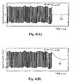
- the recording signal to be applied to the rotary heads a1, b1 is switched as shown in Fig. 6 (A), wherein after the rotary head a1 has completed the writing (recording) of the track A1, the recording signal is switched to a signal having an intermediate voltage of an amplitude of the recording signal, so that a current Sim flowing through the rotary heads a1, b1 is made to be zero.
- the signal having the intermediate voltage of the amplitude of the recording signal is applied to the rotary heads a1, b1 so that the discharge signal Sd shown in Fig. 6(B) as is prevented from being overwritten to the track A1 by the rotary head b1.
- the main feature of the information signal recording apparatus 21 of the present invention is that the apparatus has signal generating means for generating the intermediate voltage of the amplitude of the recording signal so as to allow the current flowing through the rotary heads a1, b1 to be zero.
- an information signal recording apparatus 21 comprises inverter buffers I1 to I4 for inversely outputting the recording signal as well as outputting the voltage signal corresponding to the amplitude of the recording signal, a switch SW1 for switching the recording signal on or off, a differential amplifier AMP1 for operating responsive to the outputs from the switch SW1 and the inverter buffers I1 to I4.
- the inverter buffers I1 to I4 are, for instance, made of one chip IC.
- the inverter buffers I2 to I4 and resistors R4, R5 form the signal generating means 1A for generating the intermediate voltage of the amplitude of the recording signal.
- the recording signal incoming through an input terminal Ti is applied to the differential amplifier AMP1 by turning on the switch SW1 which is connected between the inverter buffer I1 and one terminal (-) of the differential amplifier AMP1.
- the output from the differential amplifier AMP1 is applied to the rotary transformers Ra, Rb shown in Fig. 4 through the resistor R3 responsive to the amplitude of the recording signal.
- the switch SW1 Upon inhibiting the recording of the recording signal, the switch SW1 is turned off.
- the intermediate voltage applied to the input terminal (+) of the differential amplifier AMP1 is applied to the rotary transformers Ra, Rb, resulting in that the current flowing through the magnetic heads a1, b1 becomes zero.
- the current of the recording signal flowing through the rotary heads a1, b1 becomes such a signal as shown in Fig. 6 (A), resulting in preventing the discharge signal Sd from being recorded on the previously recorded track.
- the signal generating means of the present invention it is possible to employ any signal generating means as far as it generates the above-mentioned intermediate voltage in the foregoing.
- the signal generating means 1B comprises a constant-voltage power supply v1 and a switch SW2 for switching the recording signal to the above-mentioned intermediate voltage from the constant-voltage power supply V1 and vice versa.
- the switch SW2 is switched to an input terminal B thereof to allow the recording signal to be inputted to an amplifier AMP2 when the recording signal is written, and is switched to an input terminal A thereof to allow the constant voltage corresponding to the intermediate voltage to be applied to the amplifier AMP2 when the recording signal is inhibited to be written.
- the voltage of the constant-voltage power supply v1 is established to be the intermediate voltage responsive to the amplitude of the recording signal preliminarily measured, and is applied to the rotary heads a1, b1 through the rotary transformers Ra, Rb when the recording signal is inhibited to be written.
- the recording signal Upon writing the recording signal, the recording signal is applied to the amplifier AMP2 to be amplified to a predetermined level and is applied to the rotary heads a1, b1 through a resister R6 and the rotary transformers Ra, Rb.
- a control pulse signal generated in a timing shown in Fig. 5 by a control pulse generating device (not shown) to allow the control of the selective switching with respect to the switches SW1, SW2.
- the above-mentioned information signal recording apparatuses 21 and 22 mentioned above are respectively equipped with the switch SW1 or SW2, however, it is possible to eliminate the switch SW1 or SW2 by constructing the signal generating means with a gate circuit as shown in Fig. 9, resulting in a simple construction.
- the signal generating means comprises an AND gate 2 for doing arithmetic with respect to the recording signal and the control pulse signal which is made to be [H] level upon writing and is made to be [L] level upon inhibition of writing, an Ex-OR gate 3 for doing arithmetic with respect to the output from the AND gate 2 and an inverse output of the control pulse signal, another Ex-OR gate 4 for doing arithmetic with respect to the output from the AND gate 2 and the inverse output of the control pulse signal, and an amplifier AMP3 for amplifying the outputs from the Ex-OR gate 3 through a resistor R7 and the outputs from the Ex-OR gate 4 through a resister R8 to a predetermined output level so as to apply to the rotary transformers Ra, Rb.
- the above-mentioned control pulse signal is the same as that used in switching the switches SW1 and SW2.
- the recording signal for example, 0010110, a binary digit information
- the outputs E1, E2 from the Ex-OR gates 3, 4 become 0010110 caused by the gate circuits 2, 3, 4 and the inverter I5, respectively, and are applied to an amplifier AMP3.
- they are applied to the rotary transformers Ra, Rb.
- the control pulse signal becomes [L] level
- the outputs E1, E2 from the Ex-OR gates 3, 4 become 0000000 and 1111111, respectively.
- the signal applied to the amplifier AMP3 through the resistors R7, R8 becomes an intermediate value of amplitudes of the binary digit signals [1] and [0], i.e., the intermediate voltage.
- the construction of the signal generating means is not limited to the one shown in Fig. 9.
- anyone that generates the intermediate value of amplitudes of the binary signal, can be employed.
- Fig. 10 a well-known push-pull type recording amplifier used in the magnetic recording of a digital information signal.
- the push-pull type recording amplifier 24 comprises an amplifier AMP4 for amplifying a recording signal to a certain level, a first transistor Tr1 of which circuit is constructed to turn on by the recording signal amplified by the amplifier AMP4, a second transistor Tr2 of which circuit is turned on by the inverted recording signal amplified by the amplifier AMP4, a constant current circuit Ia for causing a sum of currents through the first and second transistors Tr1, Tr2 to be constant, and a pulse transformer L for inducing a current which is applied to the rotary transformers Ra, Rb responsive to ON/OFF of the transistors Tr1, Tr2.
- This push-pull type recording amplifier 24 has features that it is possible to cause a constant alternate current to always flow and a construction of the circuit to be simple.
- the push-pull type recording amplifier 24 is always supplied with the recording signal.
- either of the first and second transistors Tr1, Tr2 becomes ON, resulting that the current is applied to the rotary transformers Ra, Rb.
- the discharge signal Sd is generated in the rotary heads a1, b1 in the same manner as mentioned in Description of the Related Art.
- the constant current circuit Ia in Fig. 10 is constructed of control means (a switch circuit) 25.
- the switch circuit 25 comprises a transistor Tr3 and a direct current potential source V2 and a switch SW3.
- the switch SW3 is turned off, responsive to the control pulse signal generated by the control pulse generating device as mentioned in the foregoing, resulting in that the transistor Tr3 is operative.
- current i1 from emitters of the transistors Tr1, Tr2 flows, and the recording signal is applied to the rotary transformers Ra, Rb.
- the switch SW3 When the information signal is inhibited to be recorded, the switch SW3 is turned on responsive to the control pulse signal generated by the control pulse generating device as mentioned in the foregoing. Thus, the base of the transistor Tr3 is short-circuited to the ground, and the recording signal is not applied to the rotary transformers Ra, Rb because the current i1 from the transistors Tr1, Tr2 does not flow.
- the current supplied to the transistors Tr1, Tr2 can be made to be zero irrespective of the level of the signal supplied to the amplifier 24.
- This causes the intermediate signal with respect to the amplitude of the recording signal to be supplied to the plural rotary heads a1, b1, resulting in a simple circuit construction capable of preventing discharge signal Sd from generating.
- each of the above switches SW1, SW2 or the switch circuit 25 is provided to a previous stage of the rotary transformers Ra, Rb for supplying the recording signal to the rotary heads a1, b1 or to that of the pulse transformer L.
- the discharge signal Sd without providing the switch to each of a plurality of rotary heads a1, b1.
- the present invention it is possible to obtain a signal of an intermediate voltage even when the signal value corresponding to an intermediate value of the amplitude of the recording signal is not included in the incoming recording signal responsive to the signal value of the digital information signal.
Landscapes
- Engineering & Computer Science (AREA)
- Multimedia (AREA)
- Digital Magnetic Recording (AREA)
Claims (5)
- Informationssignalaufzeichnungsvorrichtung zum Aufzeichnen eines Aufzeichnungssignals auf einem Magnetband (T), wobei die Vorrichtung folgendes aufweist: eine sich drehende Trommel (10), eine Vielzahl von sich drehenden Köpfen (a1, b1), die auf der sich drehenden Trommel (10) angeordnet sind, wobei jeder der sich drehenden Köpfe (a1, b1) einen sich drehenden bzw. Drehwandler (Ra, Rb) besitzt zum Aufzeichnen des Aufzeichnungssignals, das erzeugt wird durch Verarbeitung eines digitalen Informationssignals, welches mit einer vorbestimmten Behandlung aufgezeichnet werden soll, auf das Magnetband (T), um ein vorbestimmtes Spurmuster zu bilden durch Liefern des Aufzeichnungssignals an die Vielzahl von sich drehenden Köpfen (a1, b1) durch die Drehwandler (Ra, Rb), wobei die Vorrichtung ferner folgendes aufweist:wobei eine intermittierende bzw. unterbrochene Aufzeichnung durchgeführt wird mit der Vielzahl von sich drehenden Köpfen (a1, b1), indem das Magnetband (T) langsamer laufen gelassen wird als bei einer normalen Aufzeichnung, um ein solches normales Spur-muster zu bilden, wie es bei der normalen Aufzeichnung gebildet wird, und während nicht operativer bzw. Pausen intervallen das Signal mit der mittleren Spannung der Amplitude des Aufzeichnungssignals an die Vielzahl von sich drehenden Köpfen (a1, b1) geliefert wird, um zu verhindern, dass das schon aufgezeichnete Spurmuster von den sich drehenden Köpfen (a1, b1) erneut geschrieben bzw. überschrieben wird.Signalerzeugungsmittel (1A, 1B) zum Erzeugen eines Signals mit einer mittleren Spannung einer Amplitude des Aufzeichnungssignals, das an die sich drehenden Köpfe (a1, b1) geliefert werden soll,
- Informationssignalaufzeichnungsvorrichtung gemäß Anspruch 1, wobei die Vorrichtung ferner Steuersignalerzeugungsmittel zum Erzeugen eines Steuerimpulssignals mit einem H-Pegel bzw. Hoch-Pegel und einem L-Pegel bzw. Niedrig-Pegel aufweist, und zwar ansprechend auf eine Drehung der sich drehenden Trommel (10).
- Informationssignalaufzeichnungsvorrichtung gemäß Anspruch 2, wobei die Vorrichtung ferner Schaltmittel (25) zum selektiven Schatten des Aufzeichnungssignals zu dem Signal mit der mittleren Spannung aufweist, und zwar ansprechend auf die von den Steuersignalerzeugungsmitteln erzeugten Steuerimpulssignale.
- Informationssignalaufzeichnungsvorrichtung gemäß Anspruch 1, wobei die Vorrichtung ferner folgendes aufweist:wobei dann, wenn eine intermittierende bzw, unterbrochene Aufzeichnung durchgeführt wird mit der Vielzahl von sich drehenden Köpfen (a1, b1), indem das Magnetband (T) langsamer laufen gelassen wird als bei einer normalen Aufzeichnung, um ein solches normales Spurmuster zu bilden, wie es bei der normalen Aufzeichnung gebildet wird, sowie während nicht operativer bzw. Pausenintervallen, die Versorgung der Vielzahl von sich drehenden Köpfen (a1, b1) mit dem Aufzeichnungssignal durch die Steuermittel unterbrochen wird.einen Aufzeichnungsverstärker (24) vom Push-Pull-Typ mit Transistoren (Tr1, Tr2) zum Liefern des Aufzeichnungssignals an die Vielzahl von sich drehenden Köpfen (a1, b1) durch eine Schaltoperation der Transistoren (Tr1, Tr2); undSteuermittel zum Steuern von Strömen, die durch die Transistoren (Tr1, Tr2) fließen,
- Informationssignalaufzeichnungsvorrichtung gemäß Anspruch 4, wobei die Vorrichtung ferner Steuersignalerzeugungsmittel zum Erzeugen eines Steuerimpulssignals mit einem H-Pegel bzw. Hoch-Pegel und einem L-Pegel bzw. Niedrig-Pegel aufweist, und zwar ansprechend auf eine Drehung der sich drehenden Trommel (10), wobei die Versorgung der Vielzahl von sich drehenden Köpfen (a1, b1) mit dem Aufzeichnungssignal durch die Steuermittel ansprechend auf das von den Steuersignalerzeugungsmitteln erzeugte Steuerimpulssignal unterbrochen wird.
Applications Claiming Priority (3)
| Application Number | Priority Date | Filing Date | Title |
|---|---|---|---|
| JP05386997A JP3339353B2 (ja) | 1997-02-21 | 1997-02-21 | 情報信号記録装置 |
| JP5386997 | 1997-02-21 | ||
| JP53869/97 | 1997-02-21 |
Publications (3)
| Publication Number | Publication Date |
|---|---|
| EP0860813A2 EP0860813A2 (de) | 1998-08-26 |
| EP0860813A3 EP0860813A3 (de) | 1999-05-26 |
| EP0860813B1 true EP0860813B1 (de) | 2005-02-09 |
Family
ID=12954774
Family Applications (1)
| Application Number | Title | Priority Date | Filing Date |
|---|---|---|---|
| EP98103175A Expired - Lifetime EP0860813B1 (de) | 1997-02-21 | 1998-02-23 | Informationssignalaufzeichnungsgerät |
Country Status (4)
| Country | Link |
|---|---|
| US (1) | US6122432A (de) |
| EP (1) | EP0860813B1 (de) |
| JP (1) | JP3339353B2 (de) |
| DE (1) | DE69828913D1 (de) |
Family Cites Families (5)
| Publication number | Priority date | Publication date | Assignee | Title |
|---|---|---|---|---|
| JPS59124006A (ja) * | 1982-12-29 | 1984-07-18 | Mitsubishi Electric Corp | 長時間磁気録画再生装置 |
| US4970621A (en) * | 1988-09-09 | 1990-11-13 | Hewlett-Packard Company | Demagnetization of thin film magnetic recording transducers utilizing a decreasing AC current |
| JPH06237432A (ja) * | 1993-02-09 | 1994-08-23 | Mitsubishi Electric Corp | 間欠記録方法および装置 |
| EP0661876B1 (de) * | 1993-12-29 | 2000-02-16 | Sony Corporation | Aufzeichnungsgerät für digitale Signale |
| JP3041184B2 (ja) * | 1994-03-16 | 2000-05-15 | 株式会社日立製作所 | ディジタル情報記録装置及び記録再生装置 |
-
1997
- 1997-02-21 JP JP05386997A patent/JP3339353B2/ja not_active Expired - Fee Related
-
1998
- 1998-02-18 US US09/025,750 patent/US6122432A/en not_active Expired - Lifetime
- 1998-02-23 DE DE69828913T patent/DE69828913D1/de not_active Expired - Fee Related
- 1998-02-23 EP EP98103175A patent/EP0860813B1/de not_active Expired - Lifetime
Also Published As
| Publication number | Publication date |
|---|---|
| DE69828913D1 (de) | 2005-03-17 |
| JPH10241106A (ja) | 1998-09-11 |
| EP0860813A3 (de) | 1999-05-26 |
| US6122432A (en) | 2000-09-19 |
| EP0860813A2 (de) | 1998-08-26 |
| JP3339353B2 (ja) | 2002-10-28 |
Similar Documents
| Publication | Publication Date | Title |
|---|---|---|
| KR890003037B1 (ko) | 회전헤드형 자기기록 재생장치 | |
| KR890005008B1 (ko) | 디지탈(digital) 자기기록 재생장치 | |
| EP0860813B1 (de) | Informationssignalaufzeichnungsgerät | |
| US6512649B1 (en) | Method for differentially writing to a memory disk | |
| EP0345037B1 (de) | Gerät zur Aufnahme von digitalen Signalen | |
| CA1256204A (en) | Video tape recorder having rotary recording, auxiliary and erasing heads, a circuit for short circuiting the auxiliary head during erasing | |
| EP0341790A2 (de) | Magnetbandwiedergabemethode und -gerät mit rotierendem Trommelkopf | |
| JPS6037890A (ja) | 磁気再生装置 | |
| US5126894A (en) | Servo circuit for capstan motor | |
| JP2540881B2 (ja) | 磁気記録装置 | |
| US5276560A (en) | Rotary magnetic type recording apparatus | |
| JPH01146105A (ja) | 磁気記録再生装置 | |
| JP2580582B2 (ja) | 磁気記録再生アンプ | |
| JP2521975B2 (ja) | 磁気記録再生装置 | |
| JPS63229651A (ja) | 回転ヘツド式テ−プレコ−ダ−の記録方式 | |
| JPH0738996Y2 (ja) | マイクロコンピュータの入出力回路 | |
| JPH0341296Y2 (de) | ||
| JPH03157850A (ja) | 集積回路装置 | |
| SU1092559A1 (ru) | Устройство дл магнитной записи цифровой информации | |
| JPH01271951A (ja) | 磁気記録再生装置 | |
| JPS61265765A (ja) | 回転ヘツド式デジタルテ−プレコ−ダの再生制御方法 | |
| JPH0689401A (ja) | 磁気記録再生装置の制御信号伝送方法 | |
| JPH02134705A (ja) | 磁気記録再生装置 | |
| JPS63113883A (ja) | 磁気テ−プのコ−ド信号変更装置 | |
| JPS63138571A (ja) | 磁気記録再生装置 |
Legal Events
| Date | Code | Title | Description |
|---|---|---|---|
| PUAI | Public reference made under article 153(3) epc to a published international application that has entered the european phase |
Free format text: ORIGINAL CODE: 0009012 |
|
| AK | Designated contracting states |
Kind code of ref document: A2 Designated state(s): DE FR GB |
|
| PUAL | Search report despatched |
Free format text: ORIGINAL CODE: 0009013 |
|
| AK | Designated contracting states |
Kind code of ref document: A3 Designated state(s): AT BE CH DE DK ES FI FR GB GR IE IT LI LU MC NL PT SE |
|
| 17P | Request for examination filed |
Effective date: 19990928 |
|
| AKX | Designation fees paid |
Free format text: DE FR GB |
|
| 17Q | First examination report despatched |
Effective date: 20030911 |
|
| GRAP | Despatch of communication of intention to grant a patent |
Free format text: ORIGINAL CODE: EPIDOSNIGR1 |
|
| GRAS | Grant fee paid |
Free format text: ORIGINAL CODE: EPIDOSNIGR3 |
|
| GRAA | (expected) grant |
Free format text: ORIGINAL CODE: 0009210 |
|
| AK | Designated contracting states |
Kind code of ref document: B1 Designated state(s): DE FR GB |
|
| PG25 | Lapsed in a contracting state [announced via postgrant information from national office to epo] |
Ref country code: FR Free format text: LAPSE BECAUSE OF NON-PAYMENT OF DUE FEES Effective date: 20050209 |
|
| REG | Reference to a national code |
Ref country code: GB Ref legal event code: FG4D |
|
| REF | Corresponds to: |
Ref document number: 69828913 Country of ref document: DE Date of ref document: 20050317 Kind code of ref document: P |
|
| PG25 | Lapsed in a contracting state [announced via postgrant information from national office to epo] |
Ref country code: GB Free format text: LAPSE BECAUSE OF NON-PAYMENT OF DUE FEES Effective date: 20050509 |
|
| PG25 | Lapsed in a contracting state [announced via postgrant information from national office to epo] |
Ref country code: DE Free format text: LAPSE BECAUSE OF NON-PAYMENT OF DUE FEES Effective date: 20050901 |
|
| PLBE | No opposition filed within time limit |
Free format text: ORIGINAL CODE: 0009261 |
|
| STAA | Information on the status of an ep patent application or granted ep patent |
Free format text: STATUS: NO OPPOSITION FILED WITHIN TIME LIMIT |
|
| GBPC | Gb: european patent ceased through non-payment of renewal fee |
Effective date: 20050509 |
|
| 26N | No opposition filed |
Effective date: 20051110 |
|
| EN | Fr: translation not filed |