EP0860751B1 - Image forming apparatus - Google Patents
Image forming apparatus Download PDFInfo
- Publication number
- EP0860751B1 EP0860751B1 EP98301278A EP98301278A EP0860751B1 EP 0860751 B1 EP0860751 B1 EP 0860751B1 EP 98301278 A EP98301278 A EP 98301278A EP 98301278 A EP98301278 A EP 98301278A EP 0860751 B1 EP0860751 B1 EP 0860751B1
- Authority
- EP
- European Patent Office
- Prior art keywords
- intermediate transfer
- image
- toner
- transfer member
- transfer
- Prior art date
- Legal status (The legal status is an assumption and is not a legal conclusion. Google has not performed a legal analysis and makes no representation as to the accuracy of the status listed.)
- Expired - Lifetime
Links
- 238000012546 transfer Methods 0.000 claims description 306
- 238000004140 cleaning Methods 0.000 claims description 75
- 230000003746 surface roughness Effects 0.000 claims description 23
- 239000000463 material Substances 0.000 claims description 12
- 239000003086 colorant Substances 0.000 claims description 3
- 239000010410 layer Substances 0.000 description 43
- 238000000034 method Methods 0.000 description 42
- 239000011247 coating layer Substances 0.000 description 30
- 238000007639 printing Methods 0.000 description 22
- 229920005989 resin Polymers 0.000 description 22
- 239000011347 resin Substances 0.000 description 22
- 230000015572 biosynthetic process Effects 0.000 description 19
- 229910052751 metal Inorganic materials 0.000 description 19
- 239000002184 metal Substances 0.000 description 19
- 229920001971 elastomer Polymers 0.000 description 18
- 239000003973 paint Substances 0.000 description 16
- 229920001577 copolymer Polymers 0.000 description 15
- 230000008569 process Effects 0.000 description 15
- 239000005060 rubber Substances 0.000 description 15
- 239000000203 mixture Substances 0.000 description 13
- 238000010276 construction Methods 0.000 description 11
- 239000002245 particle Substances 0.000 description 11
- 238000012360 testing method Methods 0.000 description 11
- -1 polyethylene Polymers 0.000 description 10
- 238000001035 drying Methods 0.000 description 9
- 238000004519 manufacturing process Methods 0.000 description 8
- 230000000694 effects Effects 0.000 description 7
- 238000000576 coating method Methods 0.000 description 6
- 230000000052 comparative effect Effects 0.000 description 6
- 238000010586 diagram Methods 0.000 description 6
- 238000011156 evaluation Methods 0.000 description 6
- 230000002093 peripheral effect Effects 0.000 description 6
- PPBRXRYQALVLMV-UHFFFAOYSA-N Styrene Chemical compound C=CC1=CC=CC=C1 PPBRXRYQALVLMV-UHFFFAOYSA-N 0.000 description 5
- 229910052782 aluminium Inorganic materials 0.000 description 5
- XAGFODPZIPBFFR-UHFFFAOYSA-N aluminium Chemical compound [Al] XAGFODPZIPBFFR-UHFFFAOYSA-N 0.000 description 5
- LFQSCWFLJHTTHZ-UHFFFAOYSA-N Ethanol Chemical compound CCO LFQSCWFLJHTTHZ-UHFFFAOYSA-N 0.000 description 4
- CTQNGGLPUBDAKN-UHFFFAOYSA-N O-Xylene Chemical compound CC1=CC=CC=C1C CTQNGGLPUBDAKN-UHFFFAOYSA-N 0.000 description 4
- 230000007423 decrease Effects 0.000 description 4
- 230000005684 electric field Effects 0.000 description 4
- 238000002474 experimental method Methods 0.000 description 4
- 239000000843 powder Substances 0.000 description 4
- 229910001220 stainless steel Inorganic materials 0.000 description 4
- 239000010935 stainless steel Substances 0.000 description 4
- 238000004073 vulcanization Methods 0.000 description 4
- 239000008096 xylene Substances 0.000 description 4
- YCKRFDGAMUMZLT-UHFFFAOYSA-N Fluorine atom Chemical compound [F] YCKRFDGAMUMZLT-UHFFFAOYSA-N 0.000 description 3
- OKKJLVBELUTLKV-UHFFFAOYSA-N Methanol Chemical compound OC OKKJLVBELUTLKV-UHFFFAOYSA-N 0.000 description 3
- 229920000459 Nitrile rubber Polymers 0.000 description 3
- YXFVVABEGXRONW-UHFFFAOYSA-N Toluene Chemical compound CC1=CC=CC=C1 YXFVVABEGXRONW-UHFFFAOYSA-N 0.000 description 3
- 239000006229 carbon black Substances 0.000 description 3
- KRKNYBCHXYNGOX-UHFFFAOYSA-N citric acid Chemical compound OC(=O)CC(O)(C(O)=O)CC(O)=O KRKNYBCHXYNGOX-UHFFFAOYSA-N 0.000 description 3
- 238000007598 dipping method Methods 0.000 description 3
- 239000000806 elastomer Substances 0.000 description 3
- 239000011737 fluorine Substances 0.000 description 3
- 229910052731 fluorine Inorganic materials 0.000 description 3
- 238000000227 grinding Methods 0.000 description 3
- 238000012986 modification Methods 0.000 description 3
- 230000004048 modification Effects 0.000 description 3
- 230000002265 prevention Effects 0.000 description 3
- 239000002904 solvent Substances 0.000 description 3
- 238000005507 spraying Methods 0.000 description 3
- 239000004925 Acrylic resin Substances 0.000 description 2
- SOGAXMICEFXMKE-UHFFFAOYSA-N Butylmethacrylate Chemical compound CCCCOC(=O)C(C)=C SOGAXMICEFXMKE-UHFFFAOYSA-N 0.000 description 2
- OKTJSMMVPCPJKN-UHFFFAOYSA-N Carbon Chemical compound [C] OKTJSMMVPCPJKN-UHFFFAOYSA-N 0.000 description 2
- XEEYBQQBJWHFJM-UHFFFAOYSA-N Iron Chemical compound [Fe] XEEYBQQBJWHFJM-UHFFFAOYSA-N 0.000 description 2
- UFWIBTONFRDIAS-UHFFFAOYSA-N Naphthalene Chemical compound C1=CC=CC2=CC=CC=C21 UFWIBTONFRDIAS-UHFFFAOYSA-N 0.000 description 2
- 239000005062 Polybutadiene Substances 0.000 description 2
- 239000004698 Polyethylene Substances 0.000 description 2
- 239000004793 Polystyrene Substances 0.000 description 2
- 235000021355 Stearic acid Nutrition 0.000 description 2
- NINIDFKCEFEMDL-UHFFFAOYSA-N Sulfur Chemical compound [S] NINIDFKCEFEMDL-UHFFFAOYSA-N 0.000 description 2
- XLOMVQKBTHCTTD-UHFFFAOYSA-N Zinc monoxide Chemical compound [Zn]=O XLOMVQKBTHCTTD-UHFFFAOYSA-N 0.000 description 2
- 239000003795 chemical substances by application Substances 0.000 description 2
- 150000001875 compounds Chemical class 0.000 description 2
- 230000007547 defect Effects 0.000 description 2
- 239000006185 dispersion Substances 0.000 description 2
- 230000014759 maintenance of location Effects 0.000 description 2
- 238000005259 measurement Methods 0.000 description 2
- 229910044991 metal oxide Inorganic materials 0.000 description 2
- 150000004706 metal oxides Chemical class 0.000 description 2
- QIQXTHQIDYTFRH-UHFFFAOYSA-N octadecanoic acid Chemical compound CCCCCCCCCCCCCCCCCC(O)=O QIQXTHQIDYTFRH-UHFFFAOYSA-N 0.000 description 2
- OQCDKBAXFALNLD-UHFFFAOYSA-N octadecanoic acid Natural products CCCCCCCC(C)CCCCCCCCC(O)=O OQCDKBAXFALNLD-UHFFFAOYSA-N 0.000 description 2
- 230000002688 persistence Effects 0.000 description 2
- 239000011295 pitch Substances 0.000 description 2
- 239000004014 plasticizer Substances 0.000 description 2
- 229920002857 polybutadiene Polymers 0.000 description 2
- 229920000573 polyethylene Polymers 0.000 description 2
- 229920002223 polystyrene Polymers 0.000 description 2
- 229920002635 polyurethane Polymers 0.000 description 2
- 239000004814 polyurethane Substances 0.000 description 2
- 239000010734 process oil Substances 0.000 description 2
- 239000000523 sample Substances 0.000 description 2
- 238000007790 scraping Methods 0.000 description 2
- 239000002356 single layer Substances 0.000 description 2
- 239000008117 stearic acid Substances 0.000 description 2
- 229920003048 styrene butadiene rubber Polymers 0.000 description 2
- 229910052717 sulfur Inorganic materials 0.000 description 2
- 239000011593 sulfur Substances 0.000 description 2
- KUAZQDVKQLNFPE-UHFFFAOYSA-N thiram Chemical compound CN(C)C(=S)SSC(=S)N(C)C KUAZQDVKQLNFPE-UHFFFAOYSA-N 0.000 description 2
- 229960002447 thiram Drugs 0.000 description 2
- 235000014692 zinc oxide Nutrition 0.000 description 2
- 239000011787 zinc oxide Substances 0.000 description 2
- 229920000049 Carbon (fiber) Polymers 0.000 description 1
- 239000004709 Chlorinated polyethylene Substances 0.000 description 1
- 229920002943 EPDM rubber Polymers 0.000 description 1
- JIGUQPWFLRLWPJ-UHFFFAOYSA-N Ethyl acrylate Chemical compound CCOC(=O)C=C JIGUQPWFLRLWPJ-UHFFFAOYSA-N 0.000 description 1
- JOYRKODLDBILNP-UHFFFAOYSA-N Ethyl urethane Chemical compound CCOC(N)=O JOYRKODLDBILNP-UHFFFAOYSA-N 0.000 description 1
- 229920000181 Ethylene propylene rubber Polymers 0.000 description 1
- PYVHTIWHNXTVPF-UHFFFAOYSA-N F.F.F.F.C=C Chemical compound F.F.F.F.C=C PYVHTIWHNXTVPF-UHFFFAOYSA-N 0.000 description 1
- 244000043261 Hevea brasiliensis Species 0.000 description 1
- 239000004677 Nylon Substances 0.000 description 1
- 239000004952 Polyamide Substances 0.000 description 1
- 239000004721 Polyphenylene oxide Substances 0.000 description 1
- 239000004743 Polypropylene Substances 0.000 description 1
- 229920001328 Polyvinylidene chloride Polymers 0.000 description 1
- 229920007962 Styrene Methyl Methacrylate Polymers 0.000 description 1
- GWEVSGVZZGPLCZ-UHFFFAOYSA-N Titan oxide Chemical compound O=[Ti]=O GWEVSGVZZGPLCZ-UHFFFAOYSA-N 0.000 description 1
- 229920006311 Urethane elastomer Polymers 0.000 description 1
- BZHJMEDXRYGGRV-UHFFFAOYSA-N Vinyl chloride Chemical compound ClC=C BZHJMEDXRYGGRV-UHFFFAOYSA-N 0.000 description 1
- 229920002433 Vinyl chloride-vinyl acetate copolymer Polymers 0.000 description 1
- XYLMUPLGERFSHI-UHFFFAOYSA-N alpha-Methylstyrene Chemical compound CC(=C)C1=CC=CC=C1 XYLMUPLGERFSHI-UHFFFAOYSA-N 0.000 description 1
- 239000011324 bead Substances 0.000 description 1
- CQEYYJKEWSMYFG-UHFFFAOYSA-N butyl acrylate Chemical compound CCCCOC(=O)C=C CQEYYJKEWSMYFG-UHFFFAOYSA-N 0.000 description 1
- 229920005549 butyl rubber Polymers 0.000 description 1
- 229910052799 carbon Inorganic materials 0.000 description 1
- 239000004917 carbon fiber Substances 0.000 description 1
- 230000008859 change Effects 0.000 description 1
- 239000011248 coating agent Substances 0.000 description 1
- 239000002322 conducting polymer Substances 0.000 description 1
- 229920001940 conductive polymer Polymers 0.000 description 1
- 239000004020 conductor Substances 0.000 description 1
- 230000003247 decreasing effect Effects 0.000 description 1
- 238000011161 development Methods 0.000 description 1
- 238000006073 displacement reaction Methods 0.000 description 1
- 229920005558 epichlorohydrin rubber Polymers 0.000 description 1
- 239000003822 epoxy resin Substances 0.000 description 1
- 229920006244 ethylene-ethyl acrylate Polymers 0.000 description 1
- 238000001125 extrusion Methods 0.000 description 1
- 239000010439 graphite Substances 0.000 description 1
- 229910002804 graphite Inorganic materials 0.000 description 1
- 229920001519 homopolymer Polymers 0.000 description 1
- 150000004678 hydrides Chemical class 0.000 description 1
- 230000001771 impaired effect Effects 0.000 description 1
- 230000006872 improvement Effects 0.000 description 1
- 229920000554 ionomer Polymers 0.000 description 1
- 229910052742 iron Inorganic materials 0.000 description 1
- 229920003049 isoprene rubber Polymers 0.000 description 1
- 150000002576 ketones Chemical class 0.000 description 1
- 150000002689 maleic acids Chemical class 0.000 description 1
- 229920003146 methacrylic ester copolymer Polymers 0.000 description 1
- ADFPJHOAARPYLP-UHFFFAOYSA-N methyl 2-methylprop-2-enoate;styrene Chemical compound COC(=O)C(C)=C.C=CC1=CC=CC=C1 ADFPJHOAARPYLP-UHFFFAOYSA-N 0.000 description 1
- 229920003052 natural elastomer Polymers 0.000 description 1
- 229920001194 natural rubber Polymers 0.000 description 1
- 229920001778 nylon Polymers 0.000 description 1
- PNJWIWWMYCMZRO-UHFFFAOYSA-N pent‐4‐en‐2‐one Natural products CC(=O)CC=C PNJWIWWMYCMZRO-UHFFFAOYSA-N 0.000 description 1
- 239000005011 phenolic resin Substances 0.000 description 1
- CSZZVSAEGFJSQO-UHFFFAOYSA-N phenyl 2-methylprop-2-enoate;styrene Chemical compound C=CC1=CC=CC=C1.CC(=C)C(=O)OC1=CC=CC=C1 CSZZVSAEGFJSQO-UHFFFAOYSA-N 0.000 description 1
- 229920001084 poly(chloroprene) Polymers 0.000 description 1
- 229920003229 poly(methyl methacrylate) Polymers 0.000 description 1
- 229920000636 poly(norbornene) polymer Polymers 0.000 description 1
- 229920002037 poly(vinyl butyral) polymer Polymers 0.000 description 1
- 229920002589 poly(vinylethylene) polymer Polymers 0.000 description 1
- 229920002647 polyamide Polymers 0.000 description 1
- 229920006122 polyamide resin Polymers 0.000 description 1
- 229920000647 polyepoxide Polymers 0.000 description 1
- 229920000728 polyester Polymers 0.000 description 1
- 229920001225 polyester resin Polymers 0.000 description 1
- 239000004645 polyester resin Substances 0.000 description 1
- 229920013716 polyethylene resin Polymers 0.000 description 1
- 229920000098 polyolefin Polymers 0.000 description 1
- 229920006380 polyphenylene oxide Polymers 0.000 description 1
- 229920001155 polypropylene Polymers 0.000 description 1
- 229920005749 polyurethane resin Polymers 0.000 description 1
- 239000004800 polyvinyl chloride Substances 0.000 description 1
- 229920000915 polyvinyl chloride Polymers 0.000 description 1
- 239000005033 polyvinylidene chloride Substances 0.000 description 1
- 238000003825 pressing Methods 0.000 description 1
- 230000009467 reduction Effects 0.000 description 1
- 239000013557 residual solvent Substances 0.000 description 1
- 230000004044 response Effects 0.000 description 1
- 230000000717 retained effect Effects 0.000 description 1
- 150000003839 salts Chemical class 0.000 description 1
- 229920002050 silicone resin Polymers 0.000 description 1
- 229920002379 silicone rubber Polymers 0.000 description 1
- 239000004945 silicone rubber Substances 0.000 description 1
- 239000007787 solid Substances 0.000 description 1
- 238000001179 sorption measurement Methods 0.000 description 1
- 229920001909 styrene-acrylic polymer Polymers 0.000 description 1
- 239000000758 substrate Substances 0.000 description 1
- 229920002725 thermoplastic elastomer Polymers 0.000 description 1
- XOLBLPGZBRYERU-UHFFFAOYSA-N tin dioxide Chemical compound O=[Sn]=O XOLBLPGZBRYERU-UHFFFAOYSA-N 0.000 description 1
- 229910001887 tin oxide Inorganic materials 0.000 description 1
- OGIDPMRJRNCKJF-UHFFFAOYSA-N titanium oxide Inorganic materials [Ti]=O OGIDPMRJRNCKJF-UHFFFAOYSA-N 0.000 description 1
- 125000000391 vinyl group Chemical group [H]C([*])=C([H])[H] 0.000 description 1
- 229920002554 vinyl polymer Polymers 0.000 description 1
- 239000002699 waste material Substances 0.000 description 1
Images

Classifications
-
- G—PHYSICS
- G03—PHOTOGRAPHY; CINEMATOGRAPHY; ANALOGOUS TECHNIQUES USING WAVES OTHER THAN OPTICAL WAVES; ELECTROGRAPHY; HOLOGRAPHY
- G03G—ELECTROGRAPHY; ELECTROPHOTOGRAPHY; MAGNETOGRAPHY
- G03G15/00—Apparatus for electrographic processes using a charge pattern
- G03G15/14—Apparatus for electrographic processes using a charge pattern for transferring a pattern to a second base
- G03G15/16—Apparatus for electrographic processes using a charge pattern for transferring a pattern to a second base of a toner pattern, e.g. a powder pattern, e.g. magnetic transfer
- G03G15/1605—Apparatus for electrographic processes using a charge pattern for transferring a pattern to a second base of a toner pattern, e.g. a powder pattern, e.g. magnetic transfer using at least one intermediate support
- G03G15/161—Apparatus for electrographic processes using a charge pattern for transferring a pattern to a second base of a toner pattern, e.g. a powder pattern, e.g. magnetic transfer using at least one intermediate support with means for handling the intermediate support, e.g. heating, cleaning, coating with a transfer agent
-
- G—PHYSICS
- G03—PHOTOGRAPHY; CINEMATOGRAPHY; ANALOGOUS TECHNIQUES USING WAVES OTHER THAN OPTICAL WAVES; ELECTROGRAPHY; HOLOGRAPHY
- G03G—ELECTROGRAPHY; ELECTROPHOTOGRAPHY; MAGNETOGRAPHY
- G03G15/00—Apparatus for electrographic processes using a charge pattern
- G03G15/14—Apparatus for electrographic processes using a charge pattern for transferring a pattern to a second base
- G03G15/16—Apparatus for electrographic processes using a charge pattern for transferring a pattern to a second base of a toner pattern, e.g. a powder pattern, e.g. magnetic transfer
- G03G15/1605—Apparatus for electrographic processes using a charge pattern for transferring a pattern to a second base of a toner pattern, e.g. a powder pattern, e.g. magnetic transfer using at least one intermediate support
- G03G15/162—Apparatus for electrographic processes using a charge pattern for transferring a pattern to a second base of a toner pattern, e.g. a powder pattern, e.g. magnetic transfer using at least one intermediate support details of the the intermediate support, e.g. chemical composition
-
- G—PHYSICS
- G03—PHOTOGRAPHY; CINEMATOGRAPHY; ANALOGOUS TECHNIQUES USING WAVES OTHER THAN OPTICAL WAVES; ELECTROGRAPHY; HOLOGRAPHY
- G03G—ELECTROGRAPHY; ELECTROPHOTOGRAPHY; MAGNETOGRAPHY
- G03G2215/00—Apparatus for electrophotographic processes
- G03G2215/16—Transferring device, details
- G03G2215/1647—Cleaning of transfer member
- G03G2215/1657—Cleaning of transfer member of transfer drum
-
- G—PHYSICS
- G03—PHOTOGRAPHY; CINEMATOGRAPHY; ANALOGOUS TECHNIQUES USING WAVES OTHER THAN OPTICAL WAVES; ELECTROGRAPHY; HOLOGRAPHY
- G03G—ELECTROGRAPHY; ELECTROPHOTOGRAPHY; MAGNETOGRAPHY
- G03G2215/00—Apparatus for electrophotographic processes
- G03G2215/16—Transferring device, details
- G03G2215/1647—Cleaning of transfer member
- G03G2215/1661—Cleaning of transfer member of transfer belt
Definitions
- This invention relates to an image forming apparatus utilizing an electrophotographic process and more particularly to such an image forming apparatus as a copying machine, a laser beam printer, or a system of facsimile which forms an image by effecting primary transfer of a toner image formed on an image bearing member provisionally onto an intermediate transfer member and secondary transfer of the toner image so received on the intermediate transfer member onto a transfer material by means of a contact transfer member.
- the image forming apparatus which attains the formation of an image by effecting primary transfer of a toner image formed on a drum-shaped electrophotographic photosensitive member as an image bearing member (hereinafter referred to as a "photosensitive member") provisionally onto an intermediate transfer member and secondary transfer of the toner image so received on the intermediate transfer member onto a transfer material by means of a contact transfer member serves effectively as a color image forming apparatus or a multicolor image forming apparatus which produces an image by subjecting the plurality of component color images of a color image information or a multicolor image information to sequential superposing transfer.
- a color image or a multicolor image or as an image forming apparatus which is endowed with the ability to form a color image or the ability to form a multicolor image is synthetically reproduced. It can obtain an image which does not incur any misregister of the component color images (misregister of colors).
- the cleaning method of (c) mentioned above which utilizes in combination a mechanical force and an electrostatic force is effective in respect that it differs from such mechanical means as mentioned above.
- This method nevertheless has the problem of necessitating a cleaning step for removing the residual toner on the intermediate transfer member separately of the standard print step, suffering the inability to allow continuous printing of images of different patterns, and lowering notably the throughput of the image formation.
- the method of (d) mentioned above seems to be an effective means because the construction which comprises providing an charging device adapted to charge the residual toner on the intermediate transfer member to a reversed polarity relative to the charged potential of the photosensitive member, and causing the residual toner on the intermediate transfer member to return to the photosensitive member solely by means of the charging device is very simple. Similarly to the method of (c), however, this method necessitates a cleaning step for removing the residual toner on the intermediate transfer member separately of the standard print step which implements the formation of an image.
- the apparatus which, for improving the throughput of the formation of image, is constructed such that a next toner image on the photosensitive member is transferred onto the intermediate transfer member at the same time that the residual toner on the intermediate transfer member is returned electrostatically to the photosensitive member, the incomplete cleaning mentioned above constitutes itself a serious problem because it affects the next image.
- EP-A-0 738 938 describes an image-forming apparatus according to the preamble of claim 1 hereof.
- This invention has an object of providing an image forming apparatus which is capable of repeating complete cleaning on the intermediate transfer member thereby permitting infallible preclusion of the otherwise possible persistence of residual toner.
- This invention has another object of providing an image forming apparatus which is capable of improving the throughput of the formation of image while implementing complete cleaning of the intermediate transfer member and consequent thorough removal of the residual toner thereon.
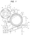
- Fig. 1 is a schematic structural diagram illustrating in an image forming apparatus according to one embodiment of this invention (as embodied in a laser beam printer which is capable of forming a color image).
- This image forming apparatus comprises a photosensitive member 1 serving as an image bearing member, a charging roller 2, an exposure device 3, a developing device 4, a transfer device 5, a fixing device 6, etc.
- the photosensitive member 1 in the present embodiment is a negatively charged organic photosensitive member which is provided on a drum substrate made of aluminum with a photoconductive layer and is rotated at a prescribed process speed in the direction of an arrow a.
- the charging roller 2 is pressed with a prescribed pressing force against the surface of the photosensitive member 1, rotated by following the rotation of the photosensitive member 1, and consequently enabled to charge the photosensitive member 1 to the potential of a prescribed polarity (in the present embodiment, the negative polarity) by applying a prescribed bias voltage (in the present embodiment, such a voltage as has an AC voltage superimpose a DC voltage of negative polarity) from a power source (not shown) to the charging roller 2.
- a prescribed bias voltage in the present embodiment, such a voltage as has an AC voltage superimpose a DC voltage of negative polarity
- the developing device 4 is provided with a Y (yellow) developer 4a, a M (magenta) developer 4b, a C (cyan) developer 4c, and a BK (black) developer 4d respectively accommodating yellow, magenta, cyan, and black toners invariably charged to normally negative polarity and is rotated by a rotating device (not shown) in the direction of an arrow mark b.
- the Y developer 4a, M developer 4b, C developer 4c, and BK developer 4d are disposed such that they are sequentially opposed to the photosensitive member 1 during the process of development.
- the transfer device 5 is provided with a roller-shaped intermediate transfer member 7 of a multilayer construction adapted to permit primary transfer thereto of a toner image formed on the photosensitive member 1 and a transfer belt 8 adapted to effect secondary transfer of the toner image on the intermediate transfer member 7 to the transfer material.
- the intermediate transfer member 7 which is composed of a conducting support member (core metal) 7a shaped like a pipe, an elastic layer 7b formed on the peripheral face thereof, and a coating layer 7c formed further thereon. It is adapted to contact the surface of the photosensitive member 1 at the position of primary transfer and also contact the surface of the transfer belt 8 at the position of secondary transfer and is rotated in the direction of an arrow mark c at substantially the same peripheral speed as the photosensitive member 1.
- a power source 9 as a means for the primary transfer is connected to the intermediate transfer member 7 and adapted to apply a prescribed primary transfer bias (DC voltage) to the intermediate transfer member 7.
- DC voltage primary transfer bias
- the transfer belt 8 is stretched and suspended as passed around a transfer roller 10a as a means for the secondary transfer and a drive roller 10b.
- the rotation of the drive roller 10b moves the upper surface of the belt in the direction of an arrow mark d.
- the transfer belt 8 is adapted to make and break contact with the intermediate transfer member 7 by a drive means (not shown).
- a power source is connected to the transfer roller 10a and adapted to apply a prescribed secondary transfer bias (DC voltage) to the transfer roller 10a.
- a roller of a multilayer construction intended as an charging member for imparting an electric charge to the toner remaining on the intermediate transfer member 7 after the secondary transfer (hereinafter referred to briefly as "ICL roller") is disposed so as to make and break contact arbitrarily therewith.
- a power source 13 applies a prescribed bias voltage (in the present embodiment, such a voltage as has an AC voltage superimpose a DC voltage of the reversed polarity (positive polarity) relative to the polarity of the normal toner in the developing device 4).
- the ICL roller 12 is composed of a conducting support member (core metal) 12a, an elastic layer 12b formed on the peripheral surface thereof, and a coating layer 12c formed further thereon.
- the photosensitive member 1 is rotated at a prescribed process speed by a drive means (not shown) and charged to a polarity (negative polarity) and a potential both of prescribed magnitudes by the charging roller 2 having a prescribed charging bias (in the present embodiment, such a voltage as has a DC voltage superimpose a DC voltage of the negative polarity) applied thereto.
- a prescribed charging bias in the present embodiment, such a voltage as has a DC voltage superimpose a DC voltage of the negative polarity
- the yellow toner image of the first component color mentioned above which has been formed and deposited on the photosensitive member 1, during the process of passing the nip part between the photosensitive member 1 and the intermediate transfer member 7, is made to effect primary transfer thereof to the peripheral surface of the intermediate transfer member 7 by virtue of the pressure developed in the nip part and the electric field formed by the primary transfer bias applied by the power source 9 to the intermediate transfer member 7.
- magenta toner image of the second component color, the cyan toner image of the third component color, and the black toner image of the fourth component color which are formed and deposited on the photosensitive member 1 respectively by the M (magenta) developer 4b, the C (cyan) developer 4c, and the BK (black) developer 4d are sequentially transferred as superposed on the intermediate transfer member 7 to complete a synthetic color toner image corresponding to the given color image.
- This step will be referred to hereinafter as "primary transfer".
- the primary transfer bias which is applied from the power source 9 for the purpose of the sequential superposing transfer of the first through fourth color toner images from the photosensitive member 1 to the intermediate transfer member 7 has the reversed polarity (positive) relative to the polarity of the toner. While the sequential superposing transfer of the first through fourth color toner images from the photosensitive member 1 to the intermediate transfer member 7 is in process, the transfer belt 8 and the ICL roller 12 are separated from the intermediate transfer member 7.
- a transfer material P such as a sheet which has discharged from a feed sheet cassette (not shown) is passed between regist rollers 14a and 14b and through a pre-transfer guide 15 and fed to a transfer nip part (near the transfer roller 10a) formed between the intermediate transfer member 7 and the transfer belt 8.
- a power source 11 applies a secondary transfer bias (DC voltage) to the transfer roller 10a to effect transfer of a synthetic color toner image from the intermediate transfer member 7 onto the transfer material P.
- This step will be referred to hereinafter as "secondary transfer”.
- the transfer material P having the synthetic color toner image transferred thereto is conveyed by the transfer belt 8 to the fixing device 6, heated thereby to have the toner image fixed thereon, and then discharged.
- the secondary transfer residual toner which remains on the intermediate transfer member 7 after surviving the secondary transfer is converted to a positive polarity by the ICL roller 12 to which a prescribed bias (in the present embodiment, such a voltage as has an AC voltage superimpose a DC voltage of the reversed polarity (positive polarity) relative to the polarity of the normal toner in the developing device 4) has been applied from a power source 13.
- a prescribed bias in the present embodiment, such a voltage as has an AC voltage superimpose a DC voltage of the reversed polarity (positive polarity) relative to the polarity of the normal toner in the developing device 4) has been applied from a power source 13.
- This toner is then electrostatically transferred to the photosensitive member 1 in response to the application of a prescribed voltage (positive polarity) from the power source 9 to the intermediate transfer member 7.
- a prescribed voltage positive polarity
- the secondary transfer residual toner adsorbed on the photosensitive member 1 is subsequently recovered by a cleaning device 16.
- a prescribed primary transfer bias (positive polarity) is applied to the intermediate transfer member 7 where the residual toner on the intermediate transfer member 7 is transferred to the photosensitive member 1 at the same time that the toner image on the photosensitive member 1 is transferred to the intermediate transfer member 7.
- the present embodiment utilizes the ICL roller 12 to charge the residual toner to the positive polarity, the toner may be charged to the negative polarity instead. In this case, the residual toner is transferred to the photosensitive member 7 by the fact that the power source 9 applies a voltage of the negative polarity to the residual toner.
- the inventors have experimentally found that the transferring property and the cleaning property expected in the apparatus of an embodiment of the invention can be stably retained for a long time by using the ICL roller 12 having applied thereto such a voltage as has an AC voltage superimpose a DC voltage of positive polarity for the purpose of imparting an electric charge to the residual toner on the intermediate transfer member 7 after the secondary transfer and adjusting the sum of the surface roughness of this ICL roller 12 and that of the intermediate transfer member 7 to a level of not less than 1 ⁇ m and not more than 50 ⁇ m.
- the toner particles of the inner part of the toner layer which have passed the ICL roller 12 and have not been much subjected relatively to electrification induce the next image to incur incomplete cleaning.
- the cleaning is effected by causing the positively charged residual toner to be recovered on the photosensitive member 1 by the electric field between the photosensitive member 1 and the intermediate transfer member 7. So, the toner which possesses a weak positive or negative charge is not recovered but suffered to manifest as a positive ghost of incomplete cleaning in the wholly black part of the next image and constitute itself a serious defect of image.
- the outermost surface part of the layer of the toner which has passed the ICL roller 12 has been intensely charged and the consequent charge is so high as to reach a level exceeding +50 ⁇ C/g.
- This toner is such that the charge of the toner of the next image which is simultaneously subjected to primary transfer and cleaned out in the primary transfer nip (position of primary transfer) between the photosensitive member 1 and the intermediate transfer member 7 is only on the order of 10 ⁇ C/g where the black toner to be used is a magnetic toner.
- the toner of this quality therefore, is electrostatically adsorbed on the toner which is possessed of intense positive charge and destined to be cleaned out, so that the adsorbed toner is returned to the photosensitive member 1 instead of being subjected to the primary transfer to the intermediate transfer member 7.
- the toner is elected to form a solid black image, therefore, the toner of the part corresponding to the preceding image is inevitably returned to the photosensitive member 1 and suffered to generate a difference in density and manifest itself as a negative ghost.
- the influence which the secondary transfer residual toner has on the image is large even when the amount of the toner is small because one part of the secondary transfer residual toner which has passed the ICL roller 12 of +50 ⁇ C/g induces the phenomenon of negative ghost by entraining five parts of the toner to be subjected to the primary transfer onto the intermediate transfer member 7 from the photosensitive member 1 of -10 ⁇ C/g.
- This phenomenon is effectively prevented by a measure which comprises decreasing the electric current passed to the ICL roller 12 and reducing the electric charge imparted to the outermost surface part of the layer of the secondary transfer residual toner.
- a measure which comprises decreasing the electric current passed to the ICL roller 12 and reducing the electric charge imparted to the outermost surface part of the layer of the secondary transfer residual toner.
- an embodiment of the invention contemplates obtaining the bias of electrification for application to the ICL roller 12 by having an AC voltage superimpose a DC voltage of negative polarity such that the sum of the surface roughness, Rz, of the ICL roller 12 and that of the intermediate transfer member 7 reaches a level of not less than 1 ⁇ m and not more than 50 ⁇ m.
- the application of the AC voltage serves the purpose of exiting not only the discharge from the ICL roller 12 but also the discharge from the intermediate transfer member 7 and enabling the electric field to extend to the inner part of the layer of the secondary transfer residual toner.
- the AC voltage so applied is increased in magnitude, since the flight of toner particles begins to occur between the ICL roller 12 and the intermediate transfer member 7, the mutual displacement of toner particles arises in the layer of the secondary transfer residual toner, the electrification is enabled to proceed more uniformly, and the flight has an effect of dispersing the secondary transfer residual toner, and the prevention of the negative ghost is promoted further as well.
- the AC voltage is preferred to have the shape of a rectangular wave which, unlike the sine wave, is capable of retaining a long time axis of peaks and consequently producing efficient electrification and flight of the secondary transfer residual toner at a low peak-to-peak voltage.
- the present embodiment has the ICL roller 12 charge the transfer residual toner by contacting the intermediate transfer member 7, it allows the ICL roller 12 and the intermediate transfer member 7 to remain apart to an extent such that the flight of toner is allowed to occur.
- the separate retention of these two components is at a disadvantage by requiring to increase the voltage applied to the ICL roller 12 as compared with the retention in contact.
- the ICL roller 12 and the intermediate transfer member 7 both have a coarse surface, however, they generate local discharge and fail to effect uniform electrification of the secondary transfer residual toner, so that no stable cleaning will be attained.
- the discharge occurs between the protrusions of the ICL roller 12 and the projections of the intermediate transfer member 7 in all the jogging parts of the surfaces of the ICL roller 12 and the intermediate transfer member 7 and the transfer residual toner existing in the depressions of the intermediate transfer member 7 result in incomplete electrification.
- the full-color mode which is productive of the secondary transfer residual toner in a relatively large amount fails to effect fully satisfactory cleaning
- the mono-color mode which produces the secondary transfer residual toner in a relatively small amount permits fully satisfactory cleaning.
- the prevention of the disadvantage mentioned above requires the sum of the surface roughness, Rz, of the ICL roller 12 and that of the intermediate transfer member 7 to be not more than 50 ⁇ m.
- the rough surface of the intermediate transfer member 7 has the possibility of entraining such defects as lowering the efficiency of the secondary transfer and imparting ruggedness to the produced image.
- the surface roughness, Rz, of the intermediate transfer member 7 is required to be not more than 30 pm. If the sum of the surface roughness, Rz, of the ICL roller 12 and that of the intermediate transfer member 7 is not more than 1 ⁇ m, the problem arises that the toner will manifest poor separability from the intermediate transfer member 7 and the efficiency of the secondary transfer will be degraded. Further, if the sum of Rz mentioned above is not more than 1 ⁇ m where the ICL roller 12 happens to be a roller that is rotated by following the rotation of the intermediate transfer member 7, the cleaning will no longer be allowed to proceed stably because the ICL roller 12 and the intermediate transfer member 7 slip over each other and the secondary transfer residual toner is not uniformly charged.
- surface roughness means the ten-point average roughness, Rz.
- the surface roughness, Rz, of the ICL roller 12 and that of the intermediate transfer member 7 which are mentioned herein refer to the numerical values obtained by a test to be conducted in accordance with JIS (Japanese Industrial Standard) B0601, with necessary modifications.
- the intermediate transfer member 7 is provided on the cylindrical conducting support member 7a made of stainless steel with the elastic layer 7b and further thereon with the coating layer 7c.
- the thickness of the elastic layer 7b is preferred to exceed 0.5 mm, particularly to fall in the approximate range of 1 - 5 mm, in consideration of such factors as the formation of a transfer nip, the misregister of color due to rotation, and the cost of material.
- the thickness of the coating layer 7c is preferred to be not more than 500 ⁇ m, especially to be in the approximate range of 5 - 100 ⁇ m, for the purpose of transmitting the flexibility of the elastic layer 7b as the lower layer to the surface of the photosensitive member 1.
- the ICL roller 12 likewise is provided on a cylindrical conducting support member 12a made of stainless steel with an elastic layer 12b and further thereon with a coating layer 12c.
- the thickness of the elastic layer 12b is preferred to be not less than 0.5 mm, especially to be in the approximate range of 1 - 5 mm and the thickness of the coating layer 12c is preferred to be not more than 500 ⁇ m, especially to be in the approximate range of 5 - 100 ⁇ m for the purpose of preventing the flexibility of the elastic layer 12b as the lower layer from being impaired.
- This invention contemplates providing the intermediate transfer member 7 and the ICL roller 12 with surfaces such that the surface roughness, Rz, of the intermediate transfer member 7 is not more than 30 ⁇ m and the sum of the surface roughness, Rz, of the intermediate layer 7 and that of the ICL roller 12 is not less than 1 ⁇ m and not more than 50 ⁇ m (the manufacture of these components provided with such surfaces as mentioned above will be described specifically herein below).
- the elastic layers 7b and 12b and the coating layers 7c and 12c respectively of the intermediate transfer member 7 and the ICL roller 12 can be made of rubber, elastomer, or resin.
- rubber or elastomer to be used effectively herein natural rubber, isoprene rubber, styrene-butadiene rubber, butadine rubber, butyl rubber, butadiene rubber, ethylene-propylene rubber, chloroprene rubber, chloro-sulfonated polyethylene, chlorinated polyethylene, acrylonitrile-butadiene rubber, urethane rubber, syndiotactic 1,2-polybutadiene, epichlorohydrin rubber, acryl rubber, silicone rubber, fluorine rubber, polynorbornene rubber, hydride nitrile rubber, and thermoplastic elastomers (such as, for example, polystyrene type, polyolefin type, polyvinyl chloride type, polyurethane type, polyamide type, polyester type, and fluorine resin type elastomers) may be cited.
- the elastic layers 7b and 12b and the coating layers 7c and 12c respectively of the intermediate transfer member 7 and the ICL roller 12 can incorporate as dispersed therein conducting materials such as carbon black, graphite, carbon fibers, metal powder, conducting metal oxide, organic metal oxide, organic metal salt, or conducting polymers for the purpose of adjusting the electric resistance thereof. They can further incorporate as dispersed therein resin powder or inorganic powder for the purpose of preventing adhesion of toner.
- such a resin as is endowed with conductivity by having dispersed therein a metal such as aluminum, iron, or stainless steel, carbon, or metal powder can be used.
- the electric resistance of the intermediate transfer member 7 is preferred to be in the range of 10 3 - 10 10 ⁇ (real resistance), particularly in the range of 10 4 - 10 9 ⁇ .
- the intermediate transfer member 7 is required to possess fully satisfactory surface resistance for the purpose of effecting discharge by contacting the ICL roller 12.
- the magnitude of the surface resistance which is effective herein is in the range of 10 6 - 10 15 ⁇ / ⁇ (determined under the conditions of normal room temperature, normal humidity, and application of 250 V). The methods for determining the real resistance and the surface resistance of the intermediate transfer member 7 will be described specifically herein below.
- the electric resistance of the ICL roller 12 is preferred to be in the range of 10 3 - 10 12 ⁇ (real resistance), more advantageously in the range of 10 5 - 10 10 ⁇ (real resistance). Further, the ICL roller 12 is required to possess such surface resistance as suffices to effect discharge on contacting the intermediate transfer member 7.
- the magnitude of the surface resistance which is effective herein is in the range of 10 6 - 10 15 ⁇ / ⁇ (determined under the conditions of normal room temperature, normal humidity, and application of 250 V).
- the reduction of the surface roughness, Rz, of the intermediate transfer member 7 and that of the ICL roller 12 can be accomplished by such methods as grinding the surface parts of the intermediate transfer member 7 and the ICL roller 12, devising the composition of a solvent to be used in applying the coating layers 7b and 12c of the intermediate transfer member 7 and the ICL roller 12, devising the conditions for drying the coating layers 7b and 12c, and devising the method of application of the coating layers 7b and 12c, for example.
- the methods for determining the real resistance and the surface resistance of the ICL roller 12 will be specifically described herein below.
- the methods which are available for grinding the surfaces of the intermediate transfer member 7 and the ICL roller 12 include a method which resorts to use of a grinder, a method which works a surface with a belt abrader, and a method which works a surface with a barrel, for example.
- a method for devising the solvent to be used in applying the coating layers 7b and 12c of the intermediate transfer member 7 and the ICL roller 12 the adoption of a solvent with low volatility tends to allay the roughness of surface where the surfaces of the intermediate transfer member 7 and the ICL roller 12 are coarsened with relatively small pitches.
- the methods which are available for applying the coating layers 7b and 12c to the intermediate transfer member 7 and the ICL roller 12 include dipping method, spray coating method, spinner coating method, bead coating method, blade coating method, beam coating method, and roll coating method, for example.
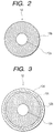
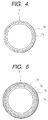
- the ICL roller 12 is provided on the conducting support member (core metal) 12a with the elastic layer 12b and the coating layer 12c. Otherwise, the ICL roller 12 of a single-layer construction which is provided on the conducting support member (core metal) 12a exclusively with the elastic layer 12b as illustrated in Fig. 2 or the ICL roller 12 of a multilayer construction which is provided on the elastic layer 12b overlying the conducting support member (core metal) 12a with two (or more) coating layers 12c and 12d as illustrated in Fig. 3, for example, may be used.
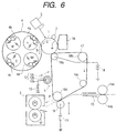
- the intermediate transfer member as depicted above, is provided on the conducting support member (core metal) 7a with the elastic layer 7b and the coating layer 7c. Otherwise, the intermediate transfer member 7 of a single-layer construction which is provided on the conducting support member (core metal) 7a exclusively with the elastic layer 7b as illustrated in Fig. 4 or the intermediate transfer member of a multilayer construction which is provided on the elastic layer 7b overlying the conducting support member (core metal) 7a with two (or more) coating layers 7c and 7d as illustrated in Fig. 5, for example, may be used.
- an intermediate transfer member 17 which, as used in the image forming apparatus (a laser beam printer capable of forming a color image) illustrated in Fig. 6, is formed in the shape of a belt provided on an elastic layer with a coating layer may be used.
- the belt-shaped intermediate transfer member 17 is stretched and suspended as passed around four rollers 18a, 18b, 18c, and 18d.
- a prescribed primary transfer bias DC voltage
- the reference numeral 19 represents a transfer roller, with the exception of which the image forming apparatus is identical with the image forming apparatus illustrated in Fig. 1.
- the throughput of the operation of continuous formation of images can be improved by charging the transfer residual toner on the intermediate transfer member 7 to negative polarity by the ICL roller 12 subsequently to the secondary transfer of the full-color image on the intermediate transfer member 7 to the transfer material and then applying the prescribed primary transfer bias (positive polarity) from the power source 9 to the intermediate transfer member 7.
- the primary transfer of the toner image of the first component color of the next image on the photosensitive member 1 to the intermediate transfer member 7 is effected at the same time that the transfer residual toner on the intermediate transfer member 7 is transferred to the photosensitive member 1 (simultaneous primary transfer and cleaning).
- the aforementioned transfer residual toner which has been transferred onto the photosensitive member 1 is recovered by the cleaning device 16.
- this construction can be expected to promote the prevention of the occurrence of incomplete cleaning and negative ghost and the improvement of the throughput of the image formation as well. Further, this construction obviates the necessity for providing the intermediate transfer member with a waste toner receptacle and, as a consequence, can contribute to miniaturize the apparatus as a whole.
- Rubber composition NBR rubber 100 parts by weight Vulcanizer (sulfur) 0.5 part by weight Vulcanization auxiliary (zinc white) 3 parts by weight Vulcanization accelerator (thiuram type) 2 parts by weight Conducting agent (carbon black) 25 parts by weight Dispersion auxiliary (stearic acid) 1.5 parts by weight Plasticizer (naphthene type process oil) 30 parts by weight
- Paint composition One-component type polyurethane 100 parts by weight Polyethylene resin particles 50 parts by weight Conducting tin oxide 20 parts by weight Xylene 500 parts by weight
- the surface roughness, Rz, of the produced ICL roller was 10 ⁇ m.
- the real resistance thereof was 2 ⁇ 10 8 ⁇ and the surface resistance thereof was 3 ⁇ 10 12 ⁇ / ⁇ .
- the numerical value of the surface roughness, Rz, of the ICL roller indicated herein was determined in accordance with the method specified in JIS B0601 with necessary modifications.
- the real resistance of the ICL roller was determined by the use of a measuring device illustrated in Fig. 7.
- This measuring device was provided with a metal roll (50 mm in outside diameter) 21 adapted to contact the ICL roller 12, a DC power source 22, a resistor 23, and a potentiometer 24. The measurement was carried out under the conditions of normal room temperature and normal humidity.
- the metal roll 21 was rotated by a drive device (not shown) and the ICL roller 12 held in contact therewith was made to follow the rotation thereof.
- the pressure of this contact was set at about 1 kgf similarly in the actual formation of an image.
- a constant DC voltage of 100 V from the DC power source 22 was applied to the metal roll 21 and the potential difference between the opposite terminals of the resistor 23 possessed of a known registance amply lower than the resistance of the ICL roller 12 under test and inserted on the downstream side of the ICL roller 12 was read on the potentiometer 24.
- the current I in flow was computed from the potential difference obtained at the opposite terminals of the resistor 23.
- the quotient of the found magnitude of the current I divided by the applied voltage of 100 V was reported as the real resistance of the ICL roller 12.
- the surface resistance of the ICL roller 12 was determined by the use of an instrument (produced by Mitsubishi Yuka K.K. and marketed under trademark designation of "Hiresta” and fitted with a HA probe) under an applied voltage of 250 V under the conditions of normal room temperature and normal humidity.
- Rubber composition EPDM 100 parts by weight Vulcanizer (sulfur) 1 part by weight Vulcanization auxiliary (zinc white) 3 parts by weight Vulcanization accelerator (thiuram type) 1.5 parts by weight Conducting agent (carbon black) 10 parts by weight Dispersion auxiliary (stearic acid) 1 part by weight Plasticizer (naphthene type process oil) 20 parts by weight
- Paint composition Methoxymethylated nylon 100 parts by weight Ethylene tetrafluoride resin particles 50 parts by weight Conducting titanium oxide 10 parts by weight Ethanol 260 parts by weight Xylene 140 parts by weight Citric acid 2 parts by weight
- the surface roughness, Rz, of the produced intermediate transfer member was 13 ⁇ m.
- the real resistance thereof was 1 ⁇ 10 7 ⁇ and the surface resistance thereof was 5 ⁇ 10 12 ⁇ / ⁇ .
- the surface roughness, Rz, of the intermediate transfer member was determined in accordance with the method specified in JIS B0601 with necessary modifications.
- the real resistance of the intermediate transfer member was determined by the use of a measuring device illustrated in Fig. 8.
- This measuring device was provided with a metal roll (40 mm in outside diameter) 21a adapted to contact the intermediate transfer member 7, a DC power source 22a, a registor 23a, and a potentiometer 24a. The measurement was carried out under the conditions of normal room temperature and normal humidity.
- the metal roll 21a was rotated by a drive device (not shown) such that the intermediate transfer member 7 held in contact therewith followed the rotation thereof at a peripheral speed of 100 mm/sec.
- the pressure of this contact was set at about 2 kgf similarly in the actual formation of an image.
- a constant DC voltage of 1 kV from the DC power source 22 was applied to the metal roll 21a and the potential difference between the opposite terminals of the resistor 23a possessed of a known resistance amply lower than the resistance of the intermediate transfer member 7 under test and inserted on the downstream side of the intermediate transfer member 7 was read on the potentiometer 24a.
- the current I in flow was computed from the potential difference obtained at the opposite terminals of the resistor 23a.
- the quotient of the found magnitude of the current I divided by the applied voltage of 1 kV was reported as the real resistance of the intermediate transfer member 7.
- the surface resistance of the intermediate transfer member 7 was determined by the use of an instrument (produced by Mitsubishi Yuka K.K. and marketed under trademark designation of "Hiresta” and fitted with a HA probe) under an applied voltage of 250 V under the conditions of normal room temperature and normal humidity.
- the ICL roller 12 and the intermediate transfer member 12 manufactured above were installed in the image forming apparatus illustrated in Fig. 1 and operated for continuously printing four sheets, 80 g/m 2 in basis weight, to produce an image of characters in the secondary color (blue), a wholly black image, an image of characters in the secondary color (blue), and a wholly white image.
- the wholly black image on the second sheet and the wholly white image on the fourth sheet were used for rating incomplete cleaning.
- the cleaning property was rated by the following method.
- the AC voltage to be applied to the ICL roller 12 is required to be a peak-to-peak voltage enough to start generation of a reversed discharge from the intermediate transfer member 7 to the ICL roller 12, preferred to possess a peak-to-peak voltage not less than twice as high as the voltage for starting discharge of the intermediate transfer member 7 and the ICL roller 12 (the voltage essentially conforming to the Paschen law), and needed to be at a still higher level where the toner is required to generate flight.
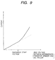
- a DC voltage was applied between the two components to measure the current flowing therebetween and obtain a graph indicating the current-voltage characteristic as illustrated in Fig. 9.
- the voltage at which the trend of the current-voltage characteristics begins to change suddenly in the graph was taken as the voltage for starting the discharge essentially conforming to the Paschen law and a peak-to-peak voltage three times as high as the voltage for starting the discharge was used for the application.
- the frequency of the AC voltage was decided by the process speed of the image forming apparatus and the pitch (process speed/frequency) which was preferred to be not more than 1 mm was set at 100 ⁇ m in the present experiment.
- the AC voltage was formed in a rectangular wave which, unlike the sine wave, is capable of retaining a long time axis of peaks and consequently producing efficient electrification and flight of the secondary transfer residual toner at a low peak-to-peak voltage.
- the cleaning property was rated with the peak-to-peak voltage for application to the ICL roller 12 set at about 1800 V because the voltage for starting discharge between the intermediate transfer member 7 and the ICL roller 12 was about 600 V and the frequency at 1000 Hz because the process speed was 100 mm/sec.
- a continuous printing test for producing a full-color image on 5000 sheets was performed to rate the cleaning property in the continuous printing. Table 1 given below shows the results of the evaluations mentioned above.
- An intermediate transfer member provided with a coating layer, about 30 ⁇ m in thickness, was obtained by preparing a paint for the formation of the coating layer similarly in Example 1, applying this paint by spray coating to a roller provided with an elastic layer obtained by the rubber composition shown in Example 1, drying the applied layer of the paint at 60°C for 30 minutes, and drying to hardness the layer at 120°C for two hours.
- the real resistance, surface resistance, and surface roughness, Rz, of the produced intermediate transfer member were respectively 3 ⁇ 10 7 ⁇ , 1 ⁇ 10 13 ⁇ / ⁇ , and 33 ⁇ m as shown in Table 1 mentioned above. These properties were determined similarly in Example 1.
- the ICL roller similar to that of Example 1 and the produced intermediate transfer member were installed in the image forming apparatus illustrated in Fig. 1 and operated to rate the cleaning property similarly in Example 1.
- the cleaning property was rated with the peak-to-peak voltage for application to the ICL roller set at about 1800 V because the voltage for starting discharge between the intermediate transfer member and the ICL roller was about 600 V and the frequency at 1000 Hz because the process speed was 100 mm/sec.
- a continuous printing test for producing a full-color image on 5000 sheets was performed to rate the cleaning property in the continuous printing. Table 1 given below shows the results of the evaluations mentioned above.
- the intermediate transfer member was manufactured similarly in Example 1.
- the real resistance, surface resistance, and surface roughness, Rz, of the produced intermediate transfer member were respectively 4 ⁇ 10 8 ⁇ , 7 ⁇ 10 12 ⁇ / ⁇ , and 24 ⁇ m as shown in Table 1 mentioned above. These properties were determined similarly in Example 1.
- the intermediate transfer member similar to that of Example 1 and the produced ICL roller were installed in the image forming apparatus illustrated in Fig. 1 and operated to rate the cleaning property similarly in Example 1.
- the cleaning property was rated with the peak-to-peak voltage for application to the ICL roller set at about 1800 V because the voltage for starting discharge between the intermediate transfer member and the ICL roller was about 600 V and the frequency at 1000 Hz because the process speed was 100 mm/sec.
- a continuous printing test for producing a full-color image on 5000 sheets was performed to rate the cleaning property in the continuous printing. The results of these evaluations are shown in Table 1 mentioned above.
- the ICL roller was manufactured similarly in Example 1.
- a rubber belt, 1 mm in thickness, was obtained by extrusion molding a rubber composition shown in Example 1, vulcanizing the extruded sheet of the rubber composition, and grinding the sheet. Then, an intermediate transfer member 17 shaped like a belt as illustrated in Fig. 6 was obtained by setting the rubber belt on an aluminum cylinder, 148 mm in outside diameter, forming a coating layer, about 50 ⁇ m in thickness, by applying the same paint for the formation of a coating layer as used in Example 1, and extracting the belt from the aluminum cylinder.
- the real resistance, surface resistance, and surface roughness, Rz, of the produced intermediate transfer member were respectively 4 ⁇ 10 6 ⁇ , 2 ⁇ 10 12 ⁇ / ⁇ , and 17 ⁇ m as shown in Table 1 mentioned above. These properties were determined similarly in Example 1.
- the intermediate transfer member similar to that of Example 1 and the produced ICL roller were installed in the image forming apparatus illustrated in Fig. 1 and operated to rate the cleaning property similarly in Example 1.
- the cleaning property was rated with the peak-to-peak voltage for application to the ICL roller set at about 1800 V because the voltage for starting discharge between the intermediate transfer member and the ICL roller was about 600 V and the frequency at 1000 Hz because the process speed was 100 mm/sec.
- a continuous printing test for producing a full-color image on 5000 sheets was performed to rate the cleaning property in the continuous printing. The results of these evaluations are shown in Table 1 mentioned above.
- Example 2 The same ICL roller and intermediate transfer member as used in Example 1 were installed in the image forming apparatus illustrated in Fig. 1.
- the cleaning property was rated by using the same conditions as in Example 1 while applying a DC voltage of positive polarity alone to the ICL roller.
- the results of the rating are shown in Table 1 mentioned above.
- the ICL roller was manufactured similarly in Example 1 and the intermediate transfer member was manufactured by using the conditions of Example 2 while changing xylene in the paint composition for coating the intermediate transfer layer to toluene and ethanol to methanol respectively.
- the real resistance, surface resistance, and surface roughness, Rz, of the produced intermediate transfer member were respectively 4 ⁇ 10 7 ⁇ , 2 ⁇ 10 13 ⁇ / ⁇ , and 44 ⁇ m as shown in Table 1 mentioned above. These properties were determined similarly in Example 1.
- Example 1 the same ICL roller as used in Example 1 and the produced intermediate transfer member were installed in the image forming apparatus illustrated in Fig. 1 and operated to rate the cleaning property similarly in Example 1.
- the cleaning property was rated with the peak-to-peak voltage for application to the ICL roller set at about 1800 V because the voltage for starting discharge between the intermediate transfer member and the ICL roller was about 600 V and the frequency at 1000 Hz because the process speed was 100 mm/sec.
- a continuous printing test for producing a full-color image on 5000 sheets was performed to rate the cleaning property in the continuous printing. The results of these evaluations are shown in Table 1 mentioned above.
- the ICL roller which was obtained by following the procedure of Example 1 while having the surface thereof ground was adopted herein.
- the real resistance, surface resistance, and surface roughness, Rz, of the produced ICL roller were respectively 5 ⁇ 10 7 ⁇ , 6 ⁇ 10 11 ⁇ / ⁇ , and 0.4 ⁇ m as shown in Table 1 mentioned above. These properties were determined similarly in Example 1.
- the real resistance, surface resistance, and surface roughness, Rz, of the produced intermediate transfer member were respectively 6 ⁇ 10 6 ⁇ , 8 ⁇ 10 11 ⁇ / ⁇ , and 0.4 ⁇ m as shown in Table 1 mentioned above. These properties were determined similarly in Example 1.
- these ICL roller and intermediate transfer member were installed in the image forming apparatus illustrated in Fig. 1 and operated to rate the cleaning property similarly in Example 1.
- the cleaning property was rated with the peak-to-peak voltage for application to the ICL roller set at about 1800 V because the voltage for starting discharge between the intermediate transfer member and the ICL roller was about 600 V and the frequency at 1000 Hz because the process speed was 100 mm/sec.
- the results of the evaluation are shown in Table 1 mentioned above.
- the intermediate transfer member could be cleaned repeatedly and fully satisfactorily and the formation of fully satisfactory images could be continued for a long time because the sum of the surface roughness, Rz, of the intermediate transfer member and that of the charging member is set at a level of not less than 1 ⁇ m and not more than 50 ⁇ m as described above.
- this invention allows the throughput of the image formation to be improved by effecting the transfer of the transfer residual toner from the intermediate transfer member to the image bearing member at the same time that the primary transfer of the toner image from the image bearing member to the intermediate member is carried out.
Landscapes
- Physics & Mathematics (AREA)
- General Physics & Mathematics (AREA)
- Electrostatic Charge, Transfer And Separation In Electrography (AREA)
- Color Electrophotography (AREA)
Applications Claiming Priority (6)
| Application Number | Priority Date | Filing Date | Title |
|---|---|---|---|
| JP3816297 | 1997-02-21 | ||
| JP3816297 | 1997-02-21 | ||
| JP38162/97 | 1997-02-21 | ||
| JP29747/98 | 1998-02-12 | ||
| JP2974798 | 1998-02-12 | ||
| JP02974798A JP4114991B2 (ja) | 1997-02-21 | 1998-02-12 | 画像形成装置 |
Publications (3)
| Publication Number | Publication Date |
|---|---|
| EP0860751A2 EP0860751A2 (en) | 1998-08-26 |
| EP0860751A3 EP0860751A3 (en) | 1999-03-03 |
| EP0860751B1 true EP0860751B1 (en) | 2004-01-21 |
Family
ID=26367983
Family Applications (1)
| Application Number | Title | Priority Date | Filing Date |
|---|---|---|---|
| EP98301278A Expired - Lifetime EP0860751B1 (en) | 1997-02-21 | 1998-02-20 | Image forming apparatus |
Country Status (4)
| Country | Link |
|---|---|
| US (1) | US5950058A (enExample) |
| EP (1) | EP0860751B1 (enExample) |
| JP (1) | JP4114991B2 (enExample) |
| DE (1) | DE69821148T2 (enExample) |
Families Citing this family (8)
| Publication number | Priority date | Publication date | Assignee | Title |
|---|---|---|---|---|
| JP3792902B2 (ja) | 1997-08-04 | 2006-07-05 | キヤノン株式会社 | 画像形成装置 |
| US6115576A (en) * | 1998-05-01 | 2000-09-05 | Ricoh Company, Ltd. | Image forming apparatus using a developing liquid and including an intermediate transfer body |
| US6592663B1 (en) | 1999-06-09 | 2003-07-15 | Ricoh Company Ltd. | Production of a GaN bulk crystal substrate and a semiconductor device formed on a GaN bulk crystal substrate |
| WO2001022173A1 (en) * | 1999-09-20 | 2001-03-29 | Hitachi, Ltd. | Electrophotographic image forming device, intermediate transfer body and electrophotograpic image forming method |
| US6516176B1 (en) * | 2001-08-13 | 2003-02-04 | Toshiba Tec Kabushiki Kaisha | Transferring body apparatus with elastic member covering surface of base of the transferring body apparatus |
| JP3927781B2 (ja) * | 2001-08-31 | 2007-06-13 | キヤノン株式会社 | プロセスカートリッジ及び中間転写ベルト |
| US8783137B2 (en) * | 2006-04-14 | 2014-07-22 | Blohm + Voss Oil Tools, Llc | Apparatus for spinning drill pipe |
| WO2008105338A1 (ja) * | 2007-02-26 | 2008-09-04 | Konica Minolta Business Technologies, Inc. | 中間転写体及び画像形成装置 |
Family Cites Families (18)
| Publication number | Priority date | Publication date | Assignee | Title |
|---|---|---|---|---|
| JPS56153357A (en) * | 1980-04-29 | 1981-11-27 | Konishiroku Photo Ind Co Ltd | Copying device |
| JPS5950475A (ja) * | 1982-09-17 | 1984-03-23 | Konishiroku Photo Ind Co Ltd | 中間転写体 |
| JPS63194272A (ja) * | 1987-02-09 | 1988-08-11 | Sharp Corp | 画像形成装置 |
| JPH01105980A (ja) * | 1987-10-19 | 1989-04-24 | Sharp Corp | 残留物転写機構を有する画像形成装置 |
| JPH04303869A (ja) * | 1991-03-30 | 1992-10-27 | Tokai Rubber Ind Ltd | 中間転写無端ベルト |
| JPH04340564A (ja) * | 1991-05-16 | 1992-11-26 | Matsushita Electric Ind Co Ltd | カラー画像形成装置 |
| JP3193113B2 (ja) * | 1992-04-21 | 2001-07-30 | 株式会社リコー | 画像形成方法 |
| JP3057121B2 (ja) * | 1992-04-28 | 2000-06-26 | 株式会社リコー | 画像形成装置 |
| JP3193796B2 (ja) * | 1992-12-29 | 2001-07-30 | キヤノン株式会社 | 画像形成装置 |
| JP3119047B2 (ja) * | 1993-09-03 | 2000-12-18 | ミノルタ株式会社 | 画像形成装置 |
| JPH0777879A (ja) * | 1993-09-07 | 1995-03-20 | Canon Inc | 画像形成装置 |
| US5565975A (en) * | 1994-06-10 | 1996-10-15 | Matsushita Electric Industrial Co., Ltd. | Color image forming apparatus and method having toner images transferred to a paper sheet |
| JPH08211755A (ja) * | 1994-11-15 | 1996-08-20 | Ricoh Co Ltd | 画像形成装置 |
| JP3198836B2 (ja) * | 1994-12-02 | 2001-08-13 | ミノルタ株式会社 | 中間転写体 |
| JP3337836B2 (ja) * | 1994-12-06 | 2002-10-28 | キヤノン株式会社 | 画像形成装置 |
| US5732310A (en) * | 1995-04-21 | 1998-03-24 | Canon Kabushiki Kaisha | Image forming apparatus having cleaning device for cleaning intermediate transfer member |
| KR970028908A (ko) * | 1995-11-24 | 1997-06-24 | 엘 드 샴펠라에레 | 싱글 패스 다색 정전 사진 프린터 |
| JPH1048962A (ja) * | 1996-07-29 | 1998-02-20 | Canon Kasei Kk | 中間転写体、画像形成装置及びその製造方法 |
-
1998
- 1998-02-12 JP JP02974798A patent/JP4114991B2/ja not_active Expired - Fee Related
- 1998-02-20 DE DE1998621148 patent/DE69821148T2/de not_active Expired - Lifetime
- 1998-02-20 EP EP98301278A patent/EP0860751B1/en not_active Expired - Lifetime
- 1998-02-20 US US09/026,947 patent/US5950058A/en not_active Expired - Lifetime
Also Published As
| Publication number | Publication date |
|---|---|
| EP0860751A3 (en) | 1999-03-03 |
| JP4114991B2 (ja) | 2008-07-09 |
| EP0860751A2 (en) | 1998-08-26 |
| US5950058A (en) | 1999-09-07 |
| DE69821148D1 (de) | 2004-02-26 |
| JPH10293480A (ja) | 1998-11-04 |
| DE69821148T2 (de) | 2004-11-18 |
Similar Documents
| Publication | Publication Date | Title |
|---|---|---|
| US5732310A (en) | Image forming apparatus having cleaning device for cleaning intermediate transfer member | |
| US5991566A (en) | Image forming method with surface potential control of intermediate transfer member | |
| US5797070A (en) | Image-forming apparatus featuring a plurality of image forming means | |
| US6097919A (en) | Image forming apparatus | |
| EP1329778A1 (en) | Image forming apparatus and intermediate transfer unit detachably mountable thereon | |
| US8135303B2 (en) | Image forming apparatus for preventing contamination of a backside of a recording medium | |
| KR100198170B1 (ko) | 화상 형성 장치 | |
| US5842080A (en) | Image forming apparatus and intermediate transfer member | |
| US5809373A (en) | Image forming apparatus which back-transfers residual toner from an intermediate transfer member to a photosensitive drum | |
| JP2002169383A (ja) | 画像形成装置及び画像形成装置の中間転写体停止位置制御方法 | |
| US20070230994A1 (en) | Image forming apparatus | |
| JP2001312159A (ja) | 中間転写体及び画像形成装置 | |
| US6175702B1 (en) | Color image forming apparatus which prevents the scatter of color characters and lines | |
| JP2004061941A (ja) | 画像形成装置 | |
| EP0860751B1 (en) | Image forming apparatus | |
| JP4255709B2 (ja) | 画像形成装置及びその転写材ジャム検出方法 | |
| JP4613672B2 (ja) | カラー画像形成装置 | |
| JPH11133761A (ja) | 画像形成装置 | |
| JP3376215B2 (ja) | 画像形成装置及び画像形成方法 | |
| JP3082546B2 (ja) | 画像形成装置 | |
| JPH11327316A (ja) | 画像形成装置 | |
| JP3372752B2 (ja) | 画像形成装置、中間転写体及び中間転写体の製造方法 | |
| KR100607966B1 (ko) | 화상이 조절되는 전자사진 방식의 인쇄기 및 그에 따른화상 조절 방법 | |
| JP3236182B2 (ja) | 画像形成装置 | |
| JP3513355B2 (ja) | 画像形成装置 |
Legal Events
| Date | Code | Title | Description |
|---|---|---|---|
| PUAI | Public reference made under article 153(3) epc to a published international application that has entered the european phase |
Free format text: ORIGINAL CODE: 0009012 |
|
| AK | Designated contracting states |
Kind code of ref document: A2 Designated state(s): DE FR GB IT |
|
| AX | Request for extension of the european patent |
Free format text: AL;LT;LV;MK;RO;SI |
|
| PUAL | Search report despatched |
Free format text: ORIGINAL CODE: 0009013 |
|
| AK | Designated contracting states |
Kind code of ref document: A3 Designated state(s): AT BE CH DE DK ES FI FR GB GR IE IT LI LU MC NL PT SE |
|
| AX | Request for extension of the european patent |
Free format text: AL;LT;LV;MK;RO;SI |
|
| 17P | Request for examination filed |
Effective date: 19990721 |
|
| AKX | Designation fees paid |
Free format text: DE FR GB IT |
|
| 17Q | First examination report despatched |
Effective date: 20011005 |
|
| GRAH | Despatch of communication of intention to grant a patent |
Free format text: ORIGINAL CODE: EPIDOS IGRA |
|
| GRAS | Grant fee paid |
Free format text: ORIGINAL CODE: EPIDOSNIGR3 |
|
| GRAA | (expected) grant |
Free format text: ORIGINAL CODE: 0009210 |
|
| AK | Designated contracting states |
Kind code of ref document: B1 Designated state(s): DE FR GB IT |
|
| REG | Reference to a national code |
Ref country code: GB Ref legal event code: FG4D |
|
| REF | Corresponds to: |
Ref document number: 69821148 Country of ref document: DE Date of ref document: 20040226 Kind code of ref document: P |
|
| ET | Fr: translation filed | ||
| PLBE | No opposition filed within time limit |
Free format text: ORIGINAL CODE: 0009261 |
|
| STAA | Information on the status of an ep patent application or granted ep patent |
Free format text: STATUS: NO OPPOSITION FILED WITHIN TIME LIMIT |
|
| 26N | No opposition filed |
Effective date: 20041022 |
|
| REG | Reference to a national code |
Ref country code: FR Ref legal event code: PLFP Year of fee payment: 18 |
|
| PGFP | Annual fee paid to national office [announced via postgrant information from national office to epo] |
Ref country code: IT Payment date: 20150206 Year of fee payment: 18 Ref country code: DE Payment date: 20150228 Year of fee payment: 18 |
|
| PGFP | Annual fee paid to national office [announced via postgrant information from national office to epo] |
Ref country code: GB Payment date: 20150220 Year of fee payment: 18 Ref country code: FR Payment date: 20150227 Year of fee payment: 18 |
|
| REG | Reference to a national code |
Ref country code: DE Ref legal event code: R119 Ref document number: 69821148 Country of ref document: DE |
|
| GBPC | Gb: european patent ceased through non-payment of renewal fee |
Effective date: 20160220 |
|
| REG | Reference to a national code |
Ref country code: FR Ref legal event code: ST Effective date: 20161028 |
|
| PG25 | Lapsed in a contracting state [announced via postgrant information from national office to epo] |
Ref country code: IT Free format text: LAPSE BECAUSE OF NON-PAYMENT OF DUE FEES Effective date: 20160220 |
|
| PG25 | Lapsed in a contracting state [announced via postgrant information from national office to epo] |
Ref country code: GB Free format text: LAPSE BECAUSE OF NON-PAYMENT OF DUE FEES Effective date: 20160220 Ref country code: FR Free format text: LAPSE BECAUSE OF NON-PAYMENT OF DUE FEES Effective date: 20160229 Ref country code: DE Free format text: LAPSE BECAUSE OF NON-PAYMENT OF DUE FEES Effective date: 20160901 |